| GENX-1B ENGINE MANUAL | Dated: 08/10/2022 | |
| EM 72-30-00 , SPECIAL PROCEDURES 003 | ||
| SPECIAL PROCEDURE - ASSEMBLY/DISASSEMBLY PROCEDURE FOR SEPARABLE AND INTEGRAL CLEVIS TORQUE SHAFT ASSEMBLY | ||
| GENX-1B ENGINE MANUAL | Dated: 08/10/2022 | |
| EM 72-30-00 , SPECIAL PROCEDURES 003 | ||
| SPECIAL PROCEDURE - ASSEMBLY/DISASSEMBLY PROCEDURE FOR SEPARABLE AND INTEGRAL CLEVIS TORQUE SHAFT ASSEMBLY | ||
| * * * FOR ALL |
| TASK 72-30-00-000-801 |
| 1 . | General. |
| A. | This procedure gives instructions to disassemble the VSV torque shaft assembly (02-005) (SIN 07501), (02-010) (SIN 07501), (02-190) (SIN 07500), or (02-200) (SIN 07500) to piece part level and assemble after the inspection process. |
| B. | The VSV torque shaft assembly disassembly/assembly process is performed during the HPC overhaul. |
| C. | This procedure is applicable to torque shaft assemblies with part numbers that follows: |
| • 2474M01 (02-005A) (SIN 07501), (02-010) (SIN 07501), (02-190A) (SIN 07500) or (02-200) (SIN 07500) - separable clevis torque shaft assembly |
| • 2570M12 (02-005) (SIN 07501) or (02-190) (SIN 07500) - integral clevis torque shaft assembly. |
| For all the other torque shaft assembly part numbers, please write to GE fleet support. |
| 2 . | Tools, Equipment, and Materials. |
| NOTE: |
|
| A. | Tools and Equipment. |
| (1) | Special Tools. None. |
| (2) | Standard Tools and Equipment. None. |
| (3) | Locally Manufactured Tools. None. |
| B. | Consumable Materials. |
|
| C. | Referenced Procedures. None |
| D. | Expendable Parts. None. |
| 3 . | Procedure. |
| CAUTION: |
|
| CAUTION: |
|
| Subtask 72-30-00-030-159 |
| A. | Disassemble the separable clevis torque shaft assembly configuration (02-005A) (SIN 07501), (02-0010) (SIN 07501), (02-190A) (SIN 07500), or (02-200) (SIN 07500), as follows: |
| NOTE: |
|
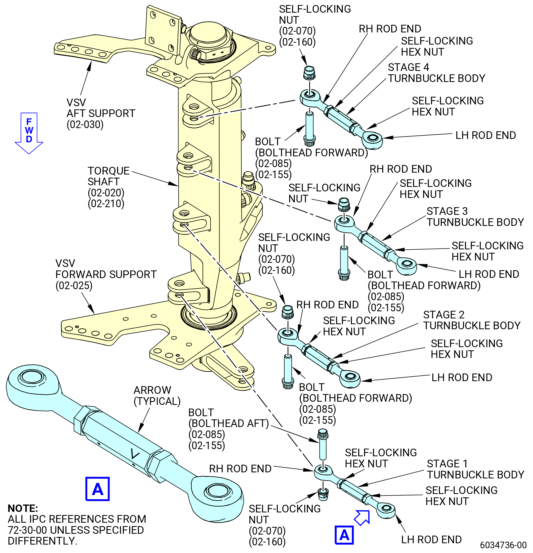
| (1) | Disconnect the IGV and stage 1-4 turnbuckles from the torque shaft clevis as follows: |
| (a) | Remove the self-locking nuts (02-080) (SIN 07501-16) and bolts (02-085) (SIN 07501-17) that connect the turnbuckles to the shaft. |
| (b) | Disassemble the torque shaft from the turnbuckles. |
| (2) | Remove the safety cable/wire on torque shaft nut and then remove the torque shaft nut (02-035) (SIN 07501-5). |
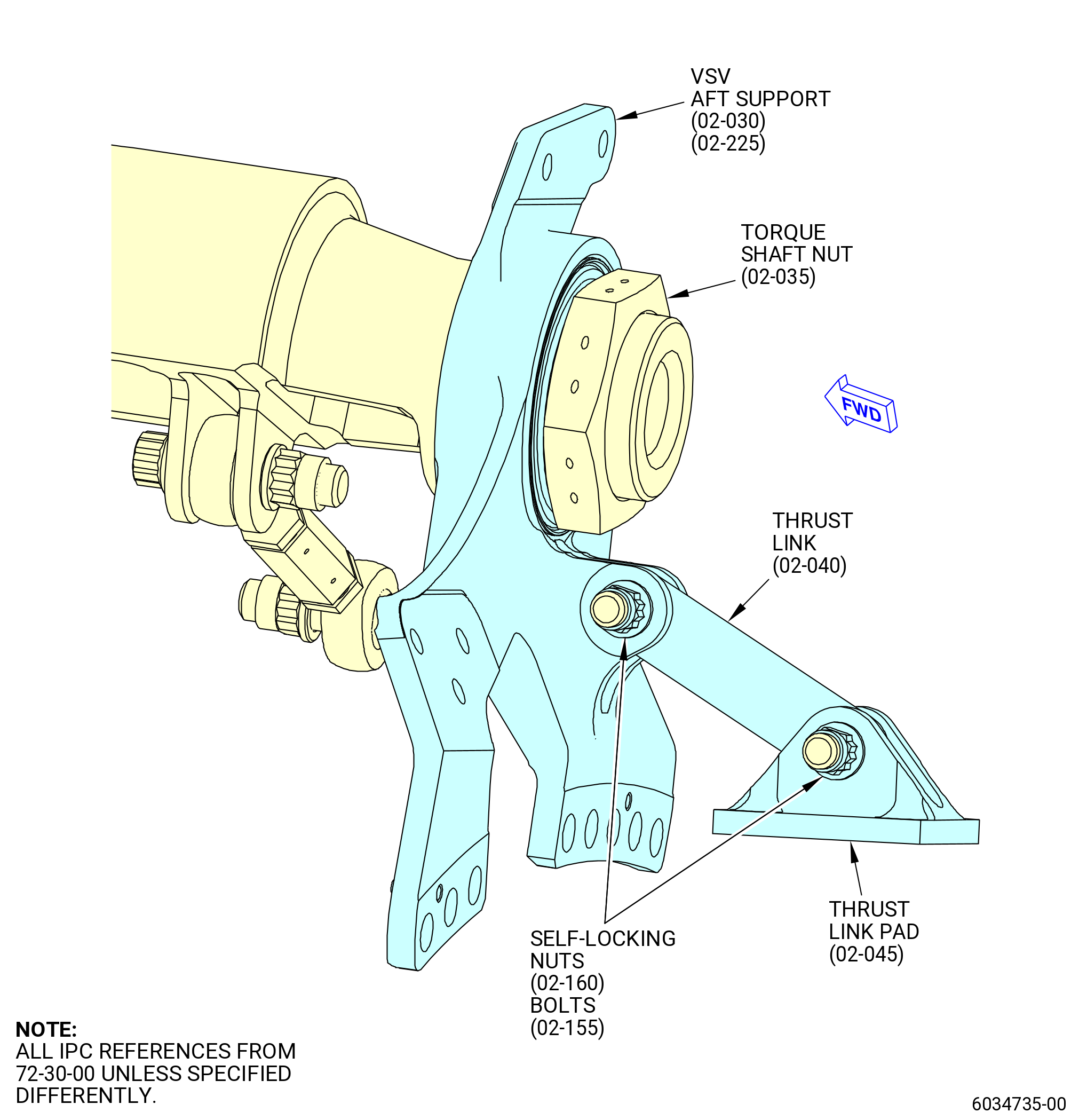
| (3) | Remove the VSV aft support assembly as follows: |
| (a) | Disassemble the VSV aft support assembly. |
| 1 | Remove two self-locking nuts (02-160) (SIN 07501-32) and bolts (02-155) (SIN 07501-31) to disassemble the assembly into aft support (02-030) (SIN 07501-4), thrust link (02-040) (SIN 07501-6), and thrust link pad (02-045) (SIN 07501-7). |
| (4) | Remove the VSV forward support (02-025) (SIN 07501-3). |
| CAUTION: |
|
| (5) | Remove the IGV and stage 1-4 clevises as follows: |
| (a) | Remove the self-locking nuts (02-070) (SIN 07501-14) or (02-075) (SIN 07501-15) that attaches the shaft clevis to the torque shaft. |
| (b) | Remove clevises (02-050) (SIN 07501-8), (02-055) (SIN 07501-9), (02-060) (SIN 07501-10), or (02-065) (SIN 07501-11) from shaft (02-020) (SIN 07501-2) or (02-210) (SIN 07500-2). |
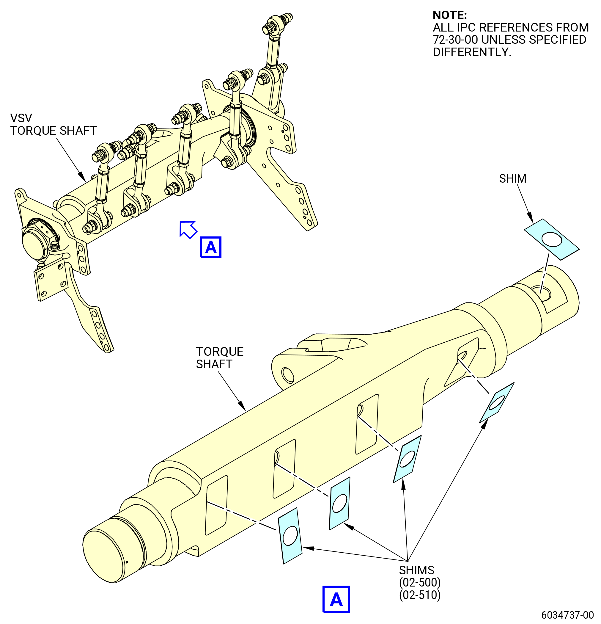
| (c) | Remove clevis shims (02-500) (SIN 7570) or (02-510) (SIN 7570). |
| Subtask 72-30-00-020-004 |
| B. | Disassemble the integral clevis torque shaft assembly configuration (02-190) (SIN 07500) or (02-005) (SIN 07501), as follows: |
| NOTE: |
|
| (1) | Disconnect the IGV and stages 1 through 4 turnbuckles from the torque shaft clevis as follows: |
| (a) | Remove the self-locking nuts (02-081) (SIN 07501-18) and bolts (02-086) (SIN 07501-9) that connect turnbuckles to the shaft. |
| (b) | Disassemble the torque shaft (02-020A) (SIN 07501-2) or (02-210A) (SIN 07500-2) from the turnbuckles. |
| (2) | Remove the safety cable/wire on torque shaft nut (02-035) (SIN 07501-5) and then remove the torque shaft nut (02-035) (SIN 07501-5). |
| (3) | Remove the VSV aft support assembly. |
| (4) | Disassemble the VSV aft support assembly as follows: |
| (a) | Remove two self-locking nuts (02-161) (SIN 07501-24) and bolts (02-156) (SIN 07501-23) to disassemble the assembly into aft support, thrust link, and thrust link pad. |
| (5) | Remove the VSV forward support (02-025) (SIN 07501-3). |
| Subtask 72-30-00-430-036 |
| C. | Assemble the separable clevis torque shaft assembly configuration (02-005A) (SIN 07501), (02-0010) (SIN 07501), (02-190A) (SIN 07500), or (02-200) (SIN 07500), as follows: |
| NOTE: |
|
| (1) | Assemble the VSV aft support assembly as follows: |
| (a) | Attach the thrust link (02-040) (SIN 07501-6) to VSV aft support (02-030) (SIN 07501-4) and thrust link pad (02-045) (SIN 07501-7) with two self-locking nuts (02-160) (SIN 07501-32) and bolts (02-155) (SIN 07501-31). |
| (b) | Torque the self-locking nuts to 331.5 to 388.5 lb in. (37.5 to 43.8 Nm), no assembly lubricant must be used. |
| (2) | Install the VSV aft support assembly to the shaft (02-020) (SIN 07501-2) or (02-210) (SIN 07500-2). |
| (3) | Install the torque shaft nut (02-035) (SIN 07501-5). Torque the nut to 663 to 777 lb in. (75.0 to 87.7 Nm), no assembly lubricant must be used. |
| (4) | Install the safety cable/wire on torque shaft nut per AS567. |
| (5) | Install the forward support (02-025) (SIN 07501) to the shaft (02-020) (SIN 07501-2) or (02-210) (SIN 07500-2). |
| (6) | Install the IGV and stages 1-4 shaft clevis (02-050) (SIN 07501-8) or (02-055) (SIN 07501-9) or (02-060) (SIN 07501-10) or (02-065) (SIN 07501-11) to the torque shaft as follows: |
| CAUTION: |
|
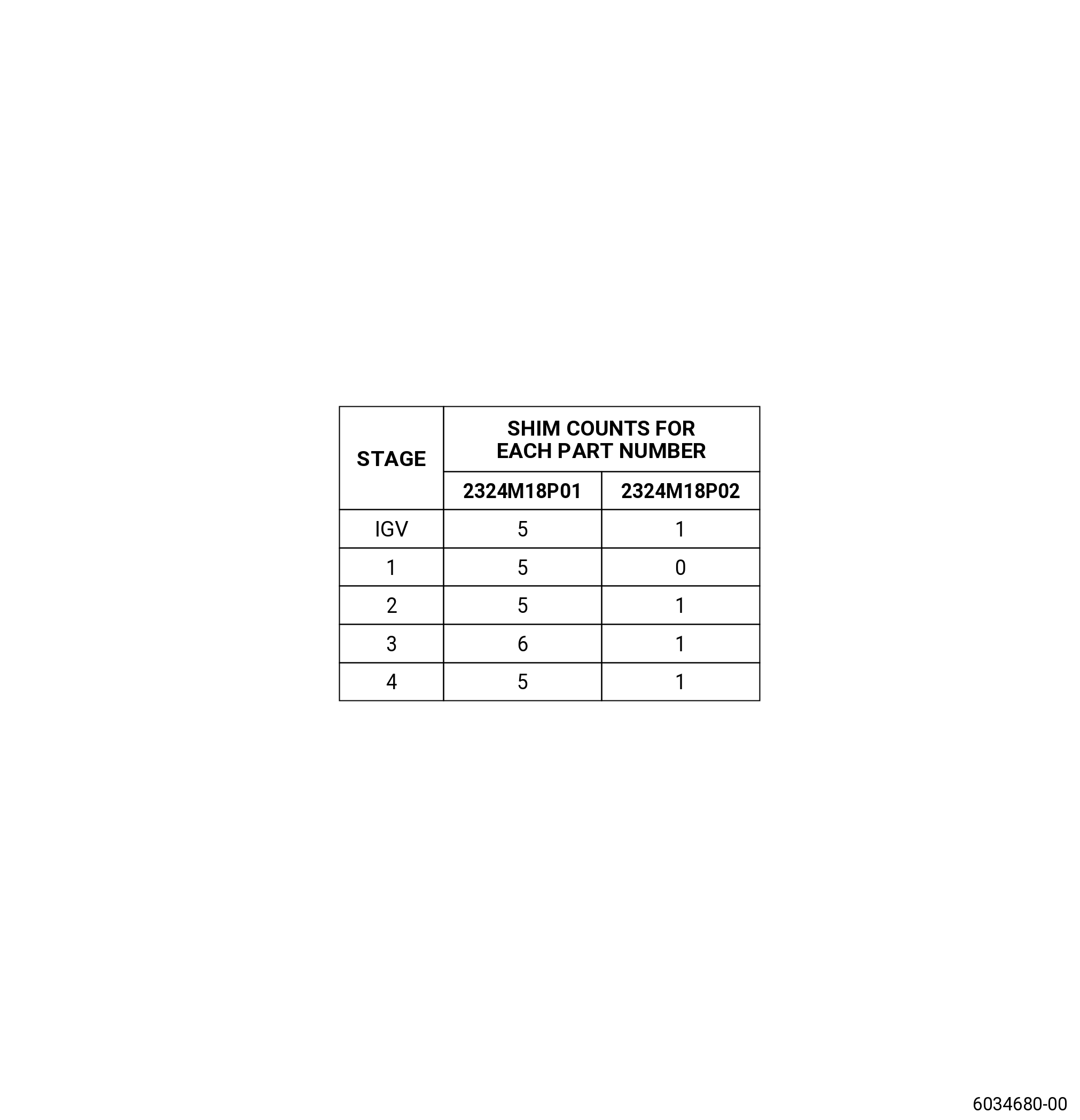
| (a) | Install shims (02-500) (SIN 07570) or (02-510) (SIN 07570) on IGV, stage 1 to 4 as for the configuration table. Refer to Figure 205. |
| (b) | Install the IGV and stages 1-4 shaft clevis (02-050) (SIN 07501-8) or (02-055) (SIN 07501-9) or (02-060) (SIN 07501-10) or (02-065) (SIN 07501-11) in the VSV torque shaft (02-020) (SIN 07501-2), or (02-210) (SIN 07500-2) and attach it with a self-locking nut and do as follows: |
| 1 | IGV, stage 1, 3 and 4 nuts - Torque the self-locking nut (02-070) (SIN 07501-14) or (02-075) (SIN 07501-15) to 515.5 to 604.5 lb in. (58.3 to 68.2 Nm), no assembly lubricant must be used. |
| 2 | Re-apply torque 515.5 to 604.5 lb in. (58.3 to 68.2 Nm). |
| 3 | Stage 2 nuts - Torque the self-locking nut (02-075) (SIN 07501-15 )to 708.5 to 831.5 lb in. (80.1 to 93.9 Nm), no assembly lubricant must be used. |
| 4 | Re-apply torque 708.5 to 831.5 lb in. (80.1 to 93.9 Nm). |
| Subtask 72-30-00-430-037 |
| A. | Assemble the integral clevis torque shaft assembly configuration (02-190) (SIN 07500) or (02-005) (SIN 07501), as follows: |
| NOTE: |
|
| (1) | Assemble the VSV aft support assembly as follows: |
| (a) | Attach the thrust link (02-040) (SIN 07501-6) to VSV aft support (02-030) (SIN 07501-4) and thrust link pad (02-045) (SIN 07501-7) with two self locking nuts (02-161) (SIN 07501-24) and bolts (02-156) (SIN 07501-23). |
| (b) | Torque the self-locking nuts (02-161) (SIN 07501-24) to 331.5 to 388.5 lb in. (37.5 to 43.8 Nm), no assembly lubricant must be used. |
| (2) | Install the VSV aft support assembly to the shaft. |
| (3) | Install the torque shaft nut. Torque the nut to 663 to 777 lb in. (75.0 to 87.7 Nm), no assembly lubricant must be used. |
| (4) | Install the safety cable/wire on torque shaft nut, refer to AS567. |
| (5) | Install the forward support to the shaft (02-025) (SIN 07501-3). |