| GENX-1B ENGINE MANUAL | Dated: 10/10/2024 | |
| EM 72-31-00 , SPECIAL PROCEDURES 001 | ||
| HIGH PRESSURE COMPRESSOR ROTOR ASSEMBLY - SPECIAL PROCEDURE 001 - MACHINING OF THE HIGH PRESSURE COMPRESSOR BLADE LOCK SETSCREWS | ||
| GENX-1B ENGINE MANUAL | Dated: 10/10/2024 | |
| EM 72-31-00 , SPECIAL PROCEDURES 001 | ||
| HIGH PRESSURE COMPRESSOR ROTOR ASSEMBLY - SPECIAL PROCEDURE 001 - MACHINING OF THE HIGH PRESSURE COMPRESSOR BLADE LOCK SETSCREWS | ||
| * * * FOR ALL |
| TASK 72-31-00-800-801 |
| 1 . | Machining of the High Pressure Compressor Blade Lock Setscrews. |
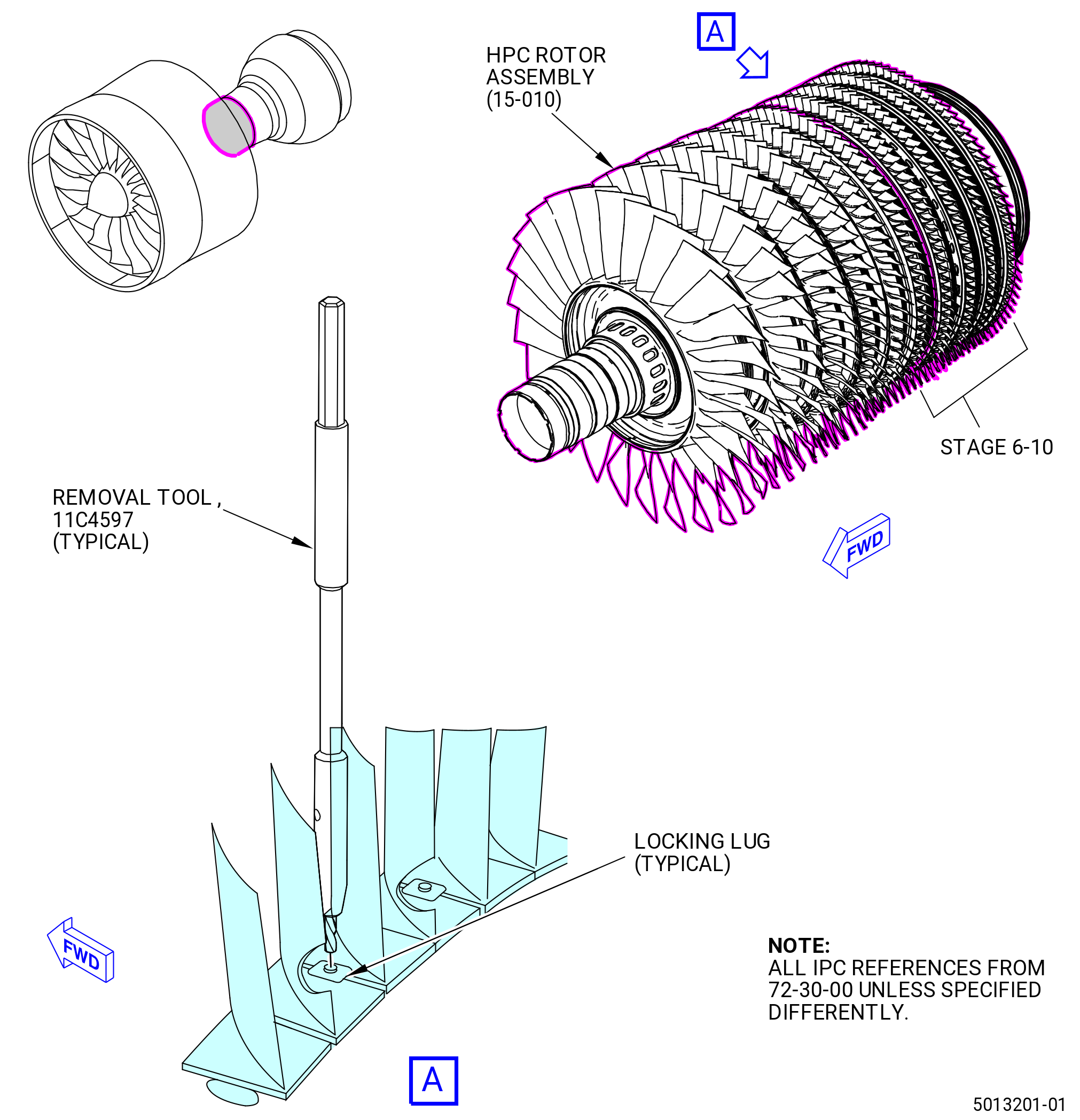
| A. | This procedure gives instructions to drill out the setscrews of the high pressure compressor (HPC) stages 6 thru 10 blade locks. |
| 2 . | Tools, Equipment, and Materials. |
| NOTE: |
|
| A. | Tools and Equipment. |
| (1) | Special Tools. |
|
| (2) | Standard Tools and Equipment. |
|
| (3) | Locally Manufactured Tools. |
|
| B. | Consumable Materials. None. |
| C. | Referenced Procedures. None. |
| D. | Expendable Parts. None. |
| E. | SPD Information. None. |
| F. | Special Solutions. None. |
| G. | Test Specimens. None. |
| 3 . | Dimensional Information. |
| None. |
| 4 . | Setup Information. |
| None. |
| 5 . | Procedure. |
| Subtask 72-31-00-040-076 |
| CAUTION: |
|
| CAUTION: |
|
| A. | Alternative Procedure Available. Use the 11C4597 removal tool to remove the locking lugs that cannot be removed with a standard hexagonal wrench. Refer to Figure 201 and do as follows: |
| Subtask 72-31-00-320-009 |
| (1) | Use a shock bar (item 7) to lightly hit the locking lug set screws to help removal. |
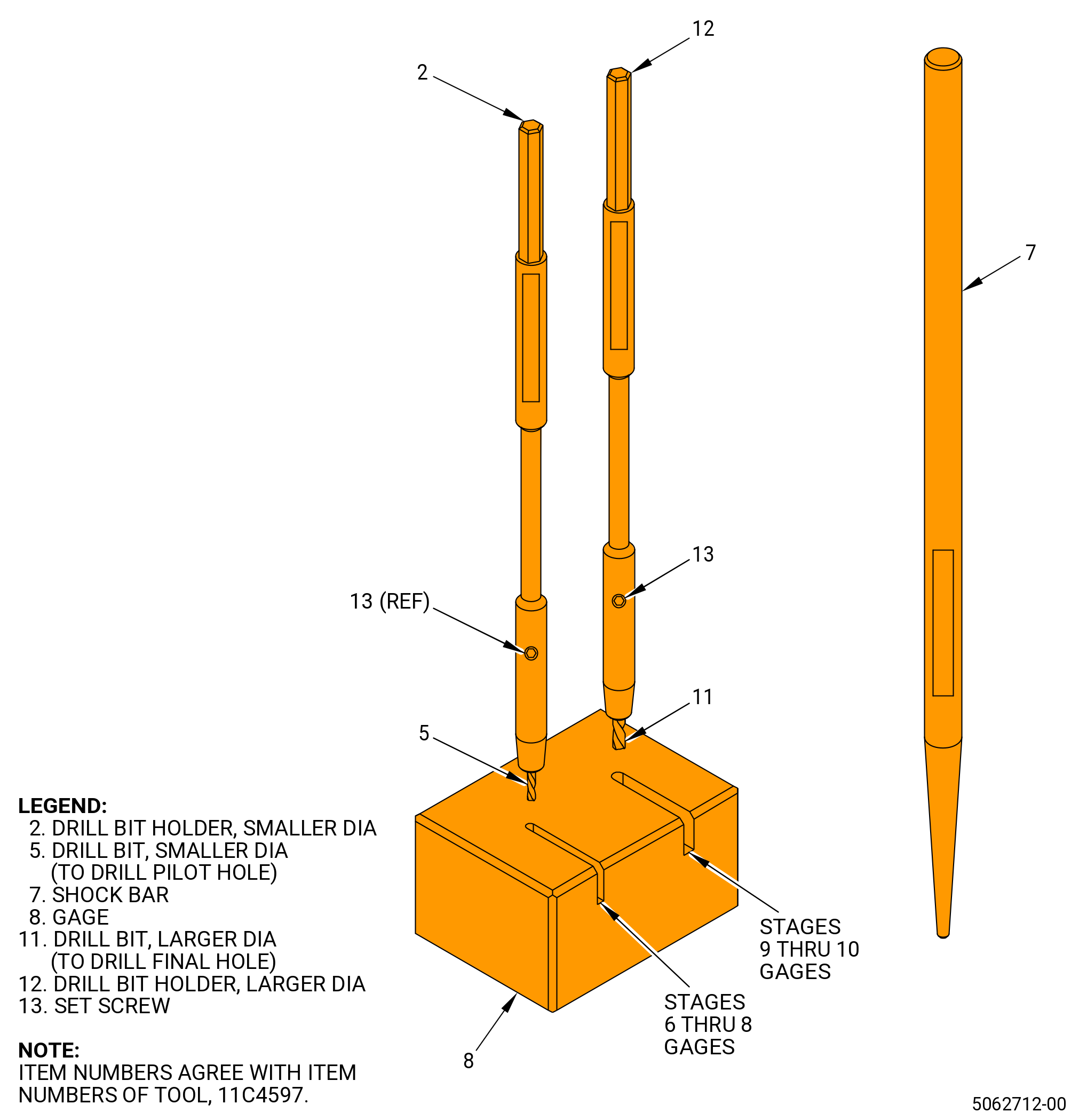
| (2) | Retrieve the smaller diameter of the two drill bit holders (item 2). |
| (3) | Loosen the set screw (item 13) so that the drill bit (item 5) can slide freely. |
| (4) | Place the drill bit (item 5) into the hole on the gage (item 8) corresponding to the compressor stage being worked on. |
| (5) | Make sure that the drill bit (item 5) is touching the inner surface of the gage (item 8) and that the drill bit holder (item 2) is touching the top surface of the gage (item 8). |
| (6) | Tighten the screw (item 13) until the drill bit (item 5) can no longer move. |
| (7) | Remove the drill bit holder (item 2) from the gage (item 8). |
| CAUTION: |
|
| (8) | Contact the locking lug set screws with the drill bit (item 5) and use a power drill to drill a pilot hole. |
| (9) | Do paragraph 5.A.(4) thru 5.A.(9) again with the larger diameter drill bit holder (item 12) and drill bit (item 11). |
| (10) | Contact the pilot hole (previously drilled in step 8) with the drill bit (item 11) and use a power drill to drill a pilot hole. |
| (11) | Remove and discard the locking lug. |
| Subtask 72-31-00-930-001 |
| A.A. | Alternative Procedure. Use a locally manufactured tool to remove the locking lugs that cannot be removed with a standard hexagonal wrench. |
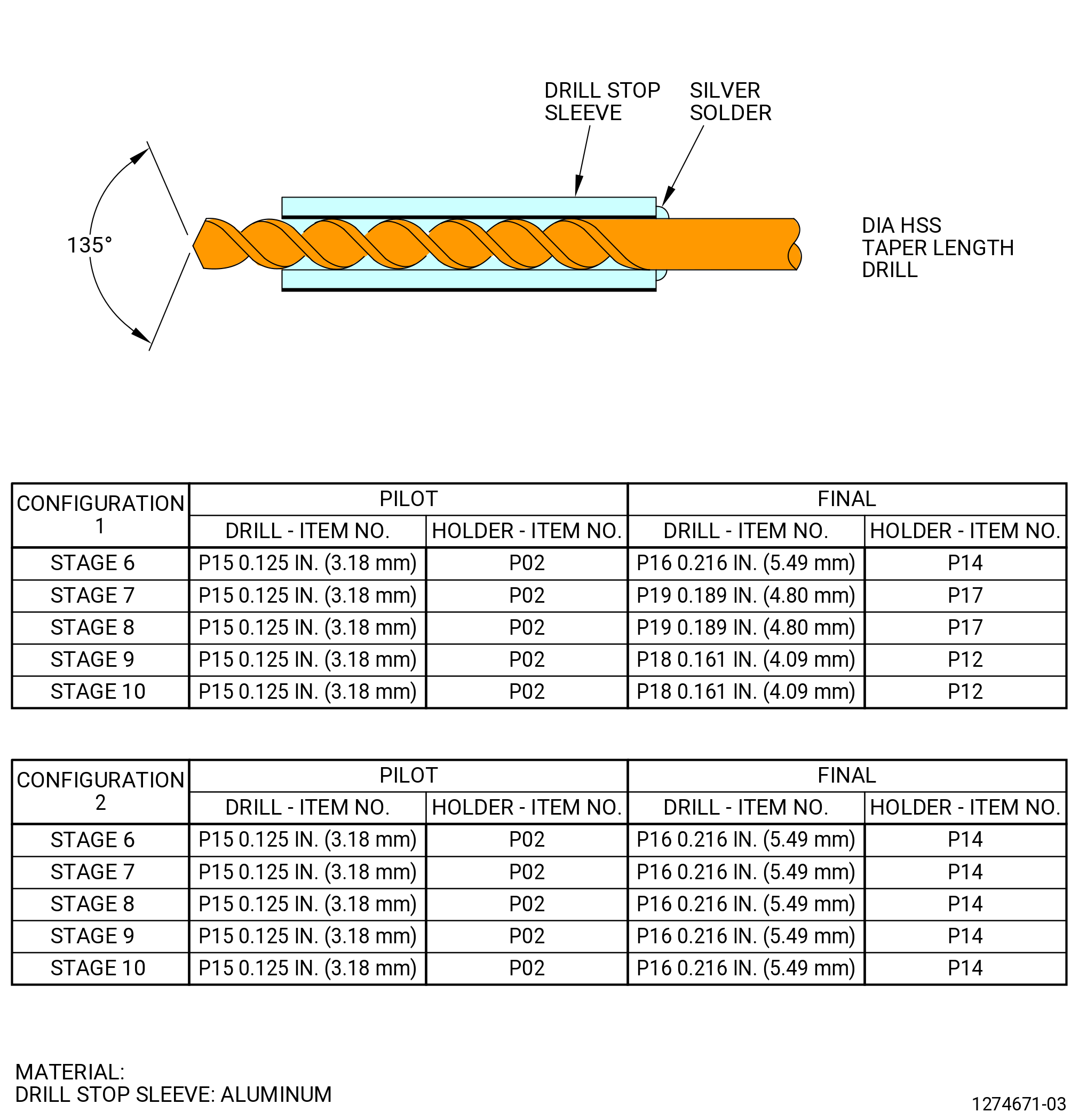
| (1) | Make the drill stop sleeve. Refer to Figure 202. |
| Subtask 72-31-00-320-005 |
| CAUTION: |
|
| (2) | Put the applicable drill in the center of the setscrew. Refer to Figure 203. |
| Subtask 72-31-00-320-006 |
| CAUTION: |
|
| (3) | Remove the setscrew threads as follows: |
| (a) | Use a sharp drill at low speed and use coolant. |
| (b) | Use a coolant feed and do not let the drill dwell. |
| (c) | Remove the set screw threads by firstly drilling a pilot hole in the set screw with the appropriate pilot drill holder and collar. The correct depth is reached when the collar touches the locking lug. |
| (d) | Change the pilot drill holder to the final drill holder using the appropriate collar. Remove the set screw threads, the correct depth is reached when the collar touches the locking lug. |
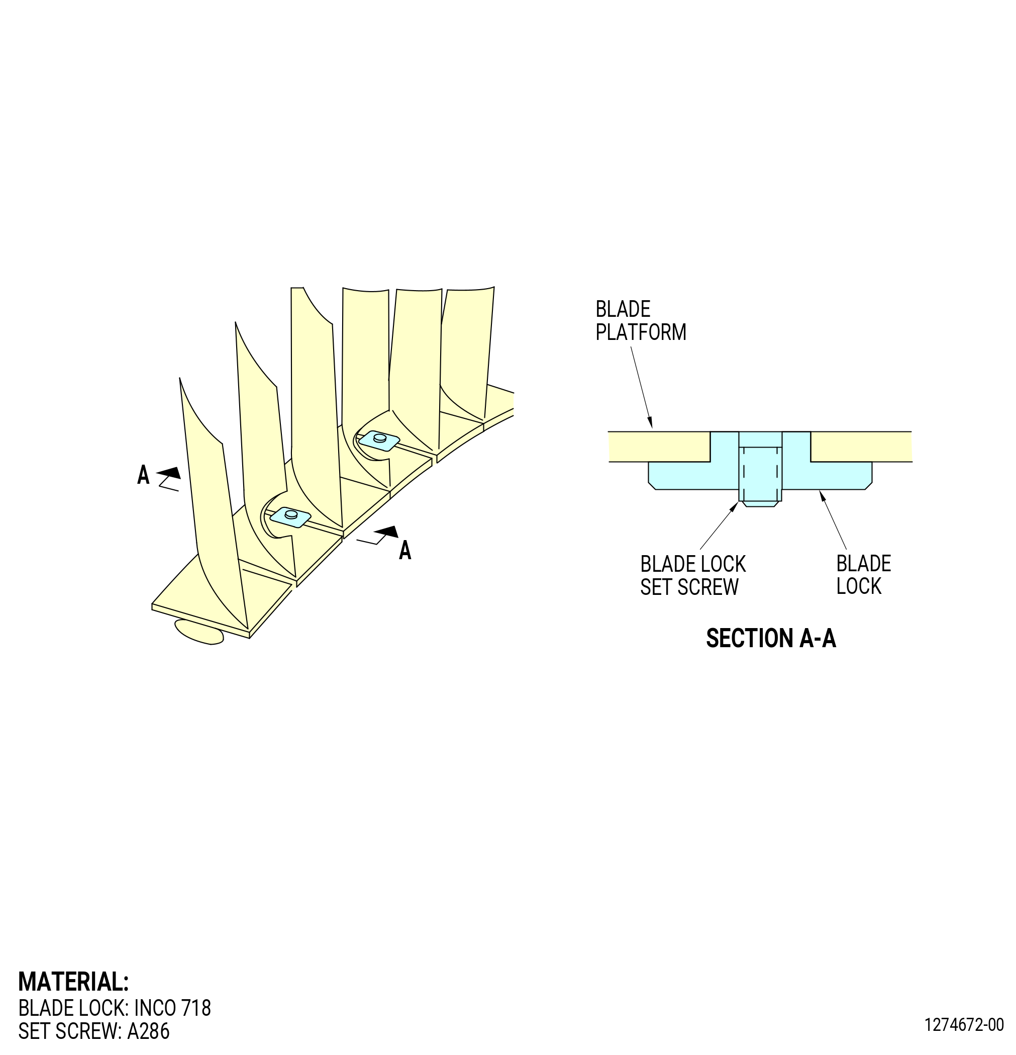
| (4) | Use a hammer and a punch to move the blade lock against the dovetail slot bottom. |
| (5) | Remove the blade lock. |
| (6) | Remove the blades. |
| Subtask 72-31-00-160-010 |
| (7) | Clean the spool with a lint-free cloth and remove all of the coolant and metal chips. |