| COMMERCIAL ENGINE STANDARD PRACTICES MANUAL | Dated: 03/09/2017 | |
| SPM 70-11-05 SAFETY CABLE METHOD NO. 3 (DANIELS (DMC) TOOL) | ||
| COMMERCIAL ENGINE STANDARD PRACTICES MANUAL | Dated: 03/09/2017 | |
| SPM 70-11-05 SAFETY CABLE METHOD NO. 3 (DANIELS (DMC) TOOL) | ||
| TASK 70-11-05-400-009 |
| 1 . | General. |
| Subtask 70-11-05-400-009 |
| A. | Method No. 3 is an equivalent alternative to: |
| TASK 70-11-03-400-007, Safety Cable Method No. 1 (Bergen Tool), and |
| TASK 70-11-04-400-008, Safety Cable Method No. 2 (Snap-On Tool). |
| B. | Safety cable is an alternative to safety wire unless specifically prohibited by the assembly procedure. Safety cable is installed through a maximum of three parts in such a way that as the fastener or part loosens, the safety cable will tighten. When the safety cable tightens it will not permit the fastener or part to turn. |
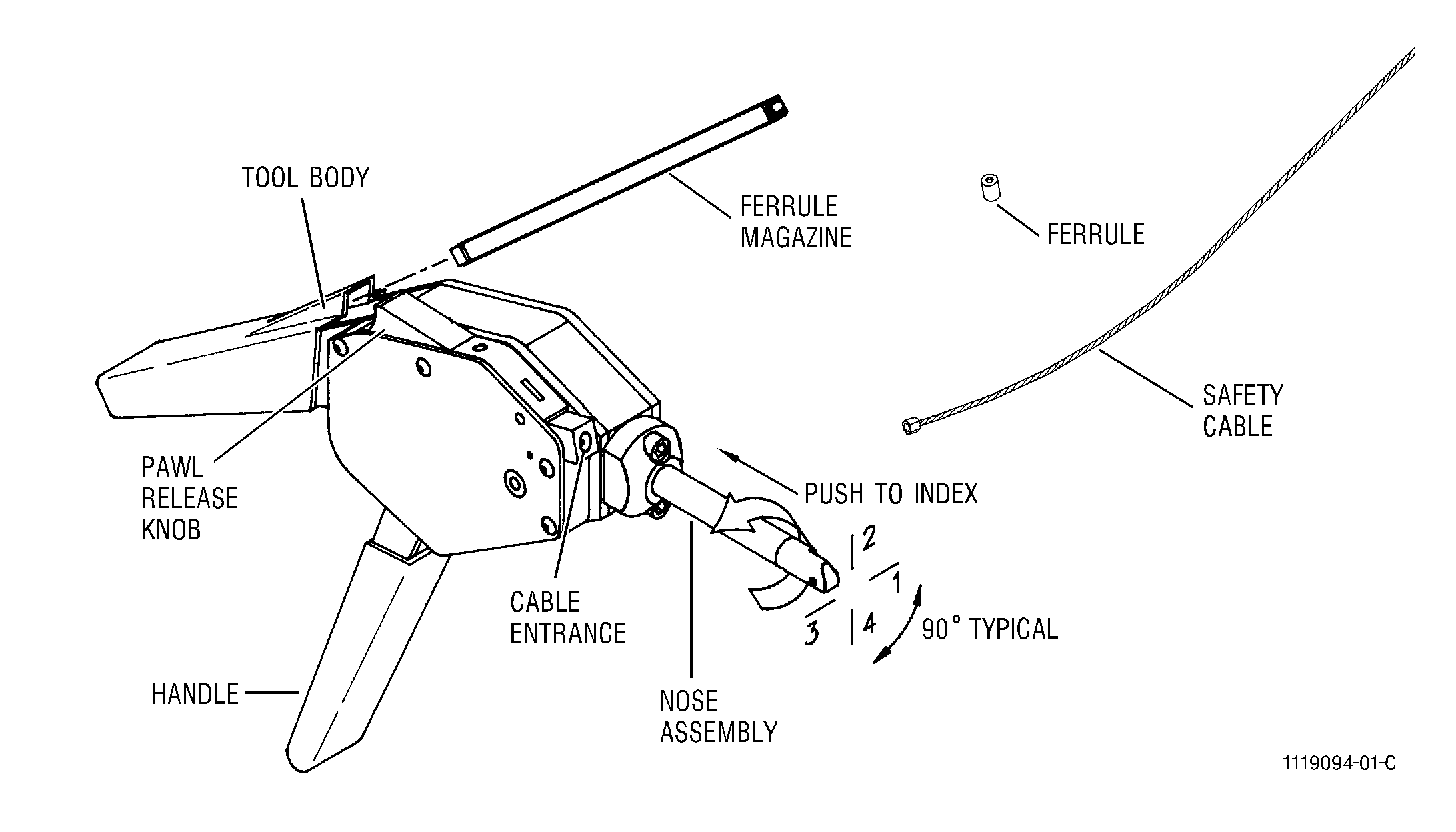
| C. | The safety cable system has three components: The safety cable, ferrules and crimping tool. See Figure 1. |
| (1) | The safety cable C10-145 is available in one size, 0.032 inch (0.81 mm), and is made of AMS 5689 (321 stainless steel) material. One end of the cable will have a cable end fitting swaged to it. The cable end fitting is made of AMS 5674 (347 stainless steel) or AMS 5689(321 Stainless Steel) material. The strands of the cable on the opposite end of the cable are fused together to prevent the cable from fraying. |
| (2) | The ferrules C10-144 are made of AMS 5674 (347 Stainless Steel) or AMS 5689 (321 Stainless Steel) material and are purchased in a spring-loaded, disposable magazine. When the safety cable is installed the ferrule will be crimped on the open end of the cable. |
| (3) | The hand-operated crimping tool C10-148 comes in two different lengths. The crimping pressure of the tool is set by the manufacturer. The primary parts of the crimping tool are the nose assembly and the tool body. This tool is used to crimp the ferrule on the end of the safety cable. The crimping tool will cut the safety |
| cable even with the ferrule at the same time the ferrule is crimped. |
| 2 . | Tools and Equipment (Method No. 3). |
| Subtask 70-11-05-400-051 |
|
| 3 . | Consumables (Method No. 3). |
| Subtask 70-11-05-400-052 |
|
| 4 . | Safety Cable Practices (Method No. 3). |
| Subtask 70-11-05-400-053 |
| A. | Where possible, install the safety cable so it does not touch other parts. |
| B. | Make sure the cable is not damaged or bent when you install the safety cable through the holes in the fastener or part. Frayed cable assemblies are not permitted. |
| C. | Install the safety cable through the existing holes only. |
| D. | Unless specified differently in the engine manual: |
| (1) | The maximum length of the safety cable between safety cabled parts is 6.0 in. (152.4 mm). |
| (2) | Do not safety more than three bolts with one safety cable. |
| (3) | Do not use safety cable on titanium fasteners. |
| 5 . | Crimping Tool Verification (Method No. 3). |
| Subtask 70-11-05-400-054 |
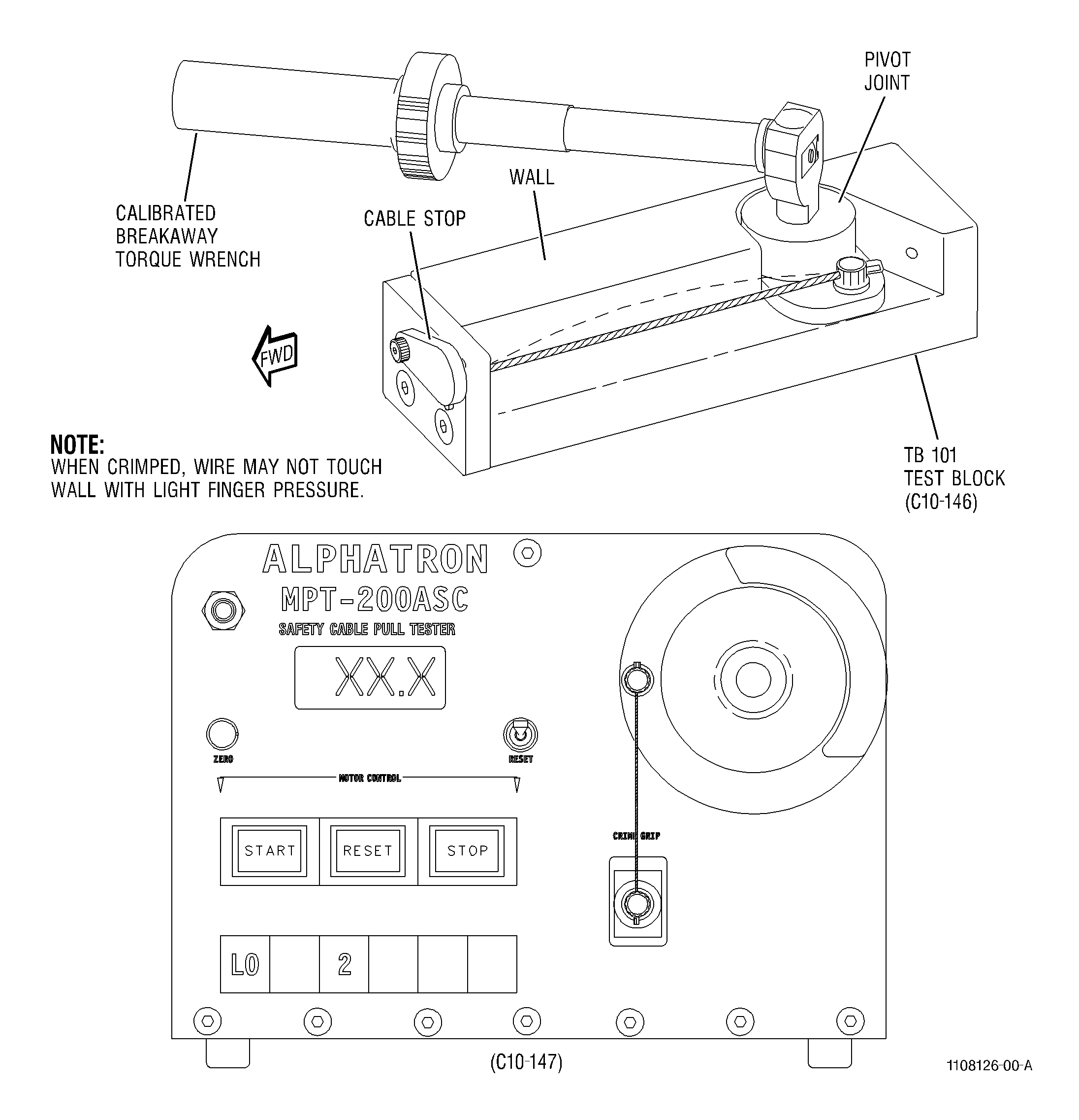
| A. | Do a pulloff load test as often as necessary to make sure the crimp done by the crimping tool meets the necessary requirements. GE Aircraft Engines recommends the pulloff load test be done at the beginning, middle and end of each shift. Do the pulloff load test as follows: See Figure 3. |
| (1) | If the test block C10-146 is not already set up, set it up at this time. Refer to manufacturers instructions for set up information. |
| (2) | Make sure the pivot joint is in the forward direction. |
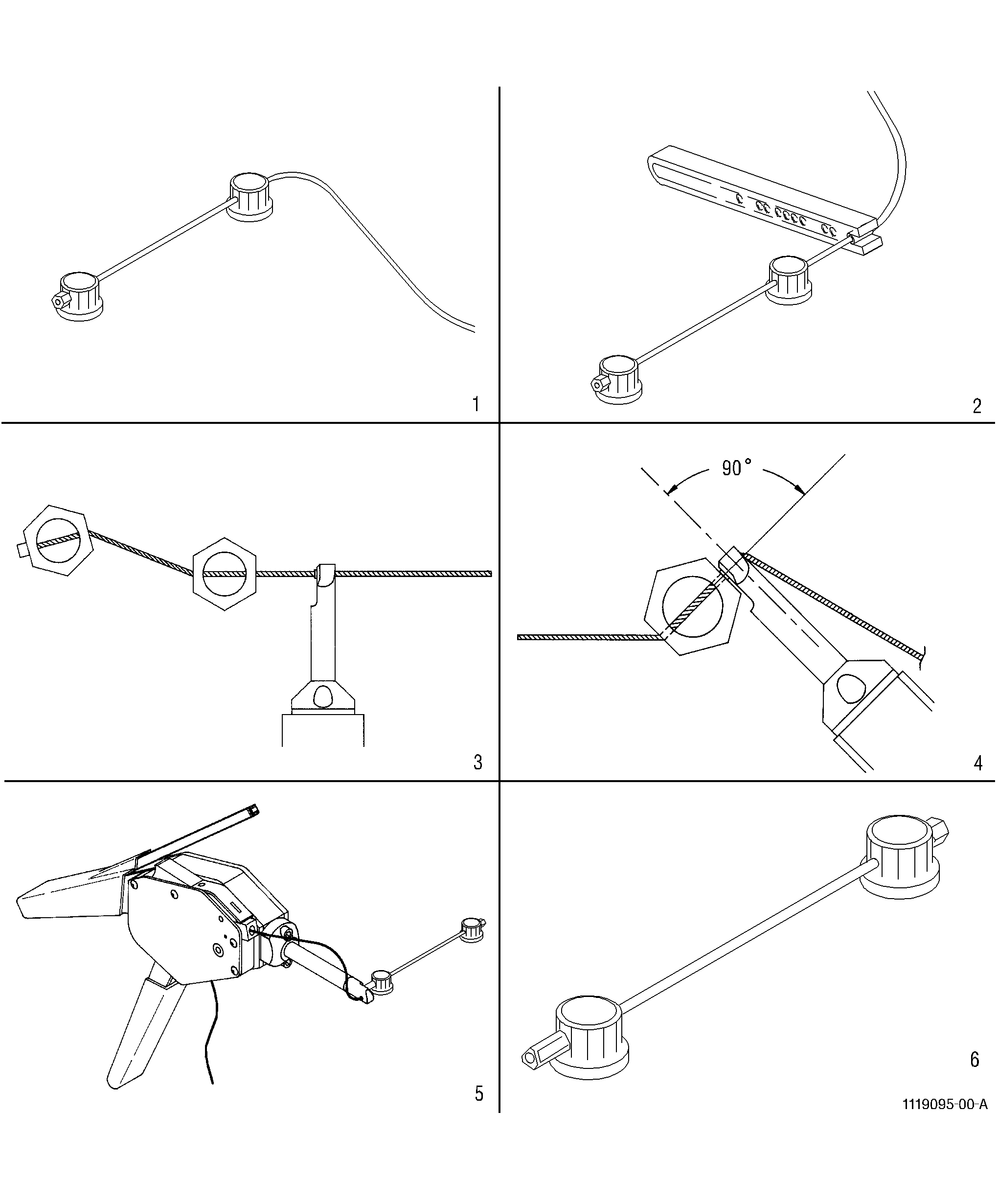
| (3) | Move the cable stop at the end of the test block. Install the safety cable C10-145 through the hole that was covered by the cable stop. Pull the safety cable through the hole in the test block and then put it through the hole in the pivot joint. Pull the cable through the hole in the pivot joint. See Figure 2, block 1. |
| (4) | Put the end of the safety cable coming out of the pivot joint through a ferrule C10-144 in the ferrule magazine. Pull the safety cable through the ferrule and use the safety cable to pull the ferrule out of the ferrule magazine. See Figure 2, block 2. |
| (5) | Put the end of the safety cable through the nose of the crimping tool C10-148 . Make sure the large hole in the nose is on the same side as the ferrule. Move the crimping tool along the safety cable until the crimping head is against the part. Make sure the ferrule goes inside the hole in the crimping head. See Figure 2, blocks 3 and 4. |
| (6) | Insert the free end of the cable into the cable entrance. Continue to push the cable into the cavity. When the free end of the cable appears at the bottom of the tool, grab the cable and pull the slack from the cable until resistance is felt. See Figure 2, block 5. |
| NOTE: |
|
| (7) | When all slack is removed from the cable, snug the tool against the fastener by using several short strokes of the handle. Release the handle to the full open position and fully close the handle to affect crimping and cutting. |
| CAUTION: |
|
| (8) | After crimping and cutting, release the tool handle and slide the tool off the crimped ferrule. Pull the excess cable from the tool. |
| (9) | Set a calibrated breakaway torque wrench to 80 lb in. (9.0 N·m). Install the torque wrench in the pivot joint on the test block C10-146 . |
| (10) | Find the center of the safety cable in the test block. Use light finger pressure and push the center of the safety cable toward the wall on the test block. The safety cable must not touch the wall. |
| (11) | If the safety cable touches the wall, the safety cable is not serviceable. Cut the safety cable with wire cutters C10-149 and remove the safety cable from the test block. Install a new safety cable and do the pulloff load test again. Make sure the tension on the safety cable is correct. Make sure when you crimp the ferrule the crimping tool is perpendicular to the safety cable and the ferrule is tightly against the bolt head. |
| (12) | Move the torque wrench handle counter-clockwise until the torque wrench clicks or the ferrule moves. If the ferrule moves before you hear the torque wrench click, adjust the crimping tool per Subtask 70-11-05-400-055, Indenter Adjustment (Method No. 3). Repeat paragraph 5. |
| (13) | Do the finger pressure test again. Find the center of the safety cable in the test block. Use light finger pressure and push the center of the safety cable toward the wall on the test block. If the safety cable does not touch the wall the crimping tool can be released for service. See Figure 3. |
| (14) | If the safety cable touches the wall, adjust the crimping tool per Subtask 70-11-05-400-055, Indenter Adjustment (Method No. 3). Repeat paragraph 5. |
| B. | Do a test to determine the exact amount of pressure necessary to cause the crimped ferrule or safety cable to fail. It is recommended that this test be done a minimum of once a month. Use a safety cable tester C10-147 to do this test. See Figure 3. Do the test according to the manufacturers instructions. This test can also be used as an alternative to the test block test. |
| 6 . | Indenter Adjustment (Method No. 3). |
| Subtask 70-11-05-400-055 |
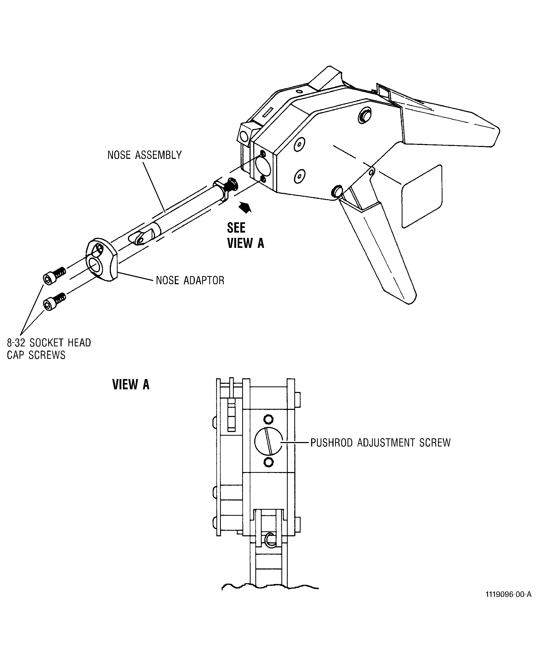
| A. | Remove the nose assembly by removing the two socket head cap screws. See Figure 4. |
| CAUTION: |
|
| B. | Adjust the pushrod adjustment screw using a 0.25 in. (6.4 mm) straight edge screw driver. Turn the pushrod adjustment screw clockwise to loosen the crimp (enlarge the gaging dimension). Turn the adjustment screw counter-clockwise to tighten the crimp (reduce gaging dimension). See Figure 4. |
| C. | Replace the nose assembly and the two socket head cap screws. Prevent binding by alternately turning each screw a small amount until tight. |
| D. | Check the calibration of the crimping tool per Subtask 70-11-05-400-054, Crimping Tool Verification (Method No. 3). |
| 7 . | Specific Techniques for Safety Cable (Method No. 3). |
| Subtask 70-11-05-400-056 |
| A. | Do a visual inspection of the holes to be safety cabled to find all damage. If the hole is damaged, replace the part or, if possible, use another hole to safety cable. |
| NOTE: |
|
| B. | Put the end of the safety cable C10-145 without the cable end fitting into the hole in the part. Pull the cable through the hole until the cable end fitting is against the part. See Figure 2, block 1. |
| NOTE: |
|
| NOTE: |
|
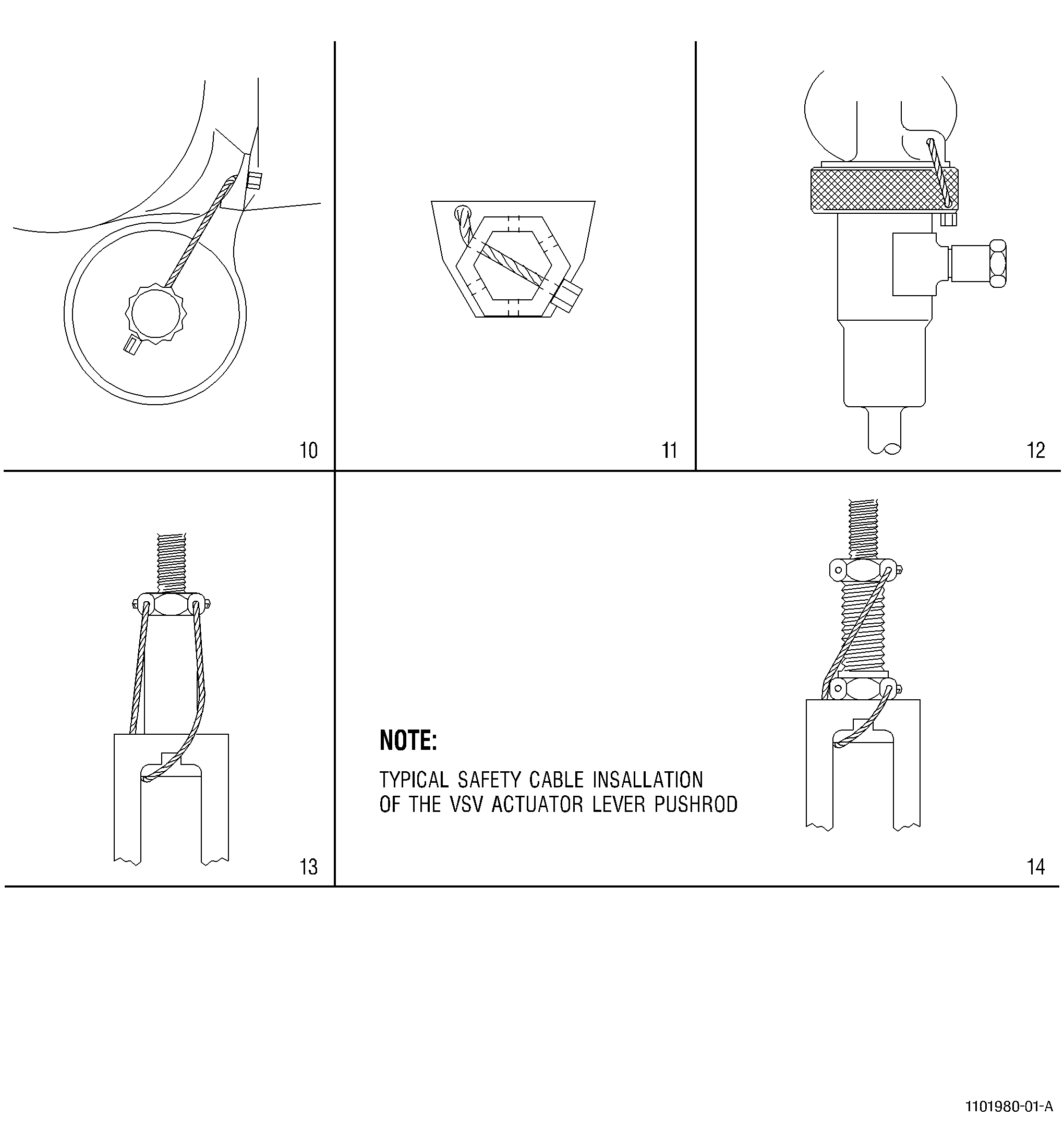
| C. | Insert the end of the cable through the second part. Choose the hole in the part that permits the cable to be as straight as possible. Pull the cable through the second part. If three parts must be safety cabled, do the same procedure for the third part. |
| D. | Put the end of the safety cable coming out of the last part to be safety cabled through a ferrule C10-144 in the ferrule magazine. Pull the safety cable through the ferrule and use the safety cable to pull the ferrule out of the ferrule magazine. See Figure 2, block 2. |
| E. | Put the end of the safety cable through the crimping head of the crimping tool C10-148 . Make sure the large hole in the crimping head is on the same side as the ferrule. Move the crimping tool along the safety cable until the crimping head is against the part. Make sure the ferrule goes inside the hole in the crimping head. See Figure 2, blocks 3 and 4. |
| F. | Insert the free end of the cable into the cable entrance. Continue to push the cable into the cavity. When the free end of the cable appears at the bottom of the tool, grab the cable and pull the slack from the cable until resistance is felt. See Figure 2, block 5. |
| NOTE: |
|
| G. | When all slack is removed from the cable, snug the tool against the fastener by using several short strokes of the handle. Release the handle to the full open position and fully close the handle to affect crimping and cutting. |
| CAUTION: |
|
| H. | After crimping and cutting, release the tool handle and slide the tool off the crimped ferrule. Pull the excess cable from the tool. |
| I. | Visually inspect safety cable for kinks, frayed wires, or improper crimps. Remove and replace safety cable if a problem exists. |
| J. | Remove and discard the unused safety cable from the bottom of the crimping tool. |
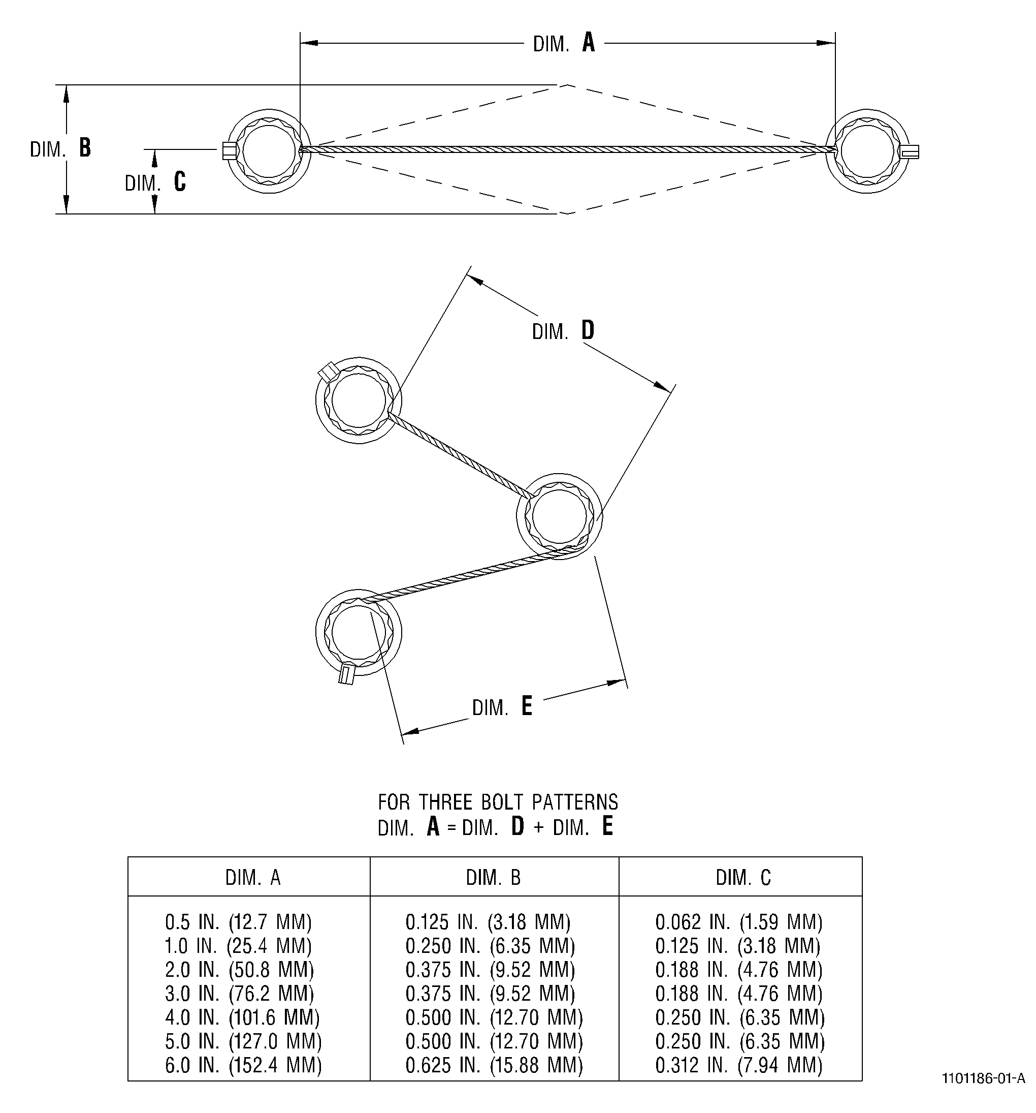
| K. | Push against the safety cable with light finger pressure halfway between the safety cabled parts. If the cable feels loose, do a dimensional check to make sure the safety cable is serviceable as follows: See Figure 5. |
| (1) | Measure the distance between the safety cabled parts. Write this measurement down as Dimension A. If three parts are safety cabled together, measure the distance between each of the parts and add the two measurements together to get Dimension A. |
| (2) | Push against the safety cable with light finger pressure halfway between two safety cabled parts. Measure the distance the safety cable moves laterally. Write this measurement down as Dimension C. |
| (3) | Compare the dimensions that were written down to the limits given in Figure 5. |
| CAUTION: |
|
| L. | If the safety cable is not in the limits given in Figure 6, cut the safety cable with wire cutters C10-149 and remove the safety cable. Install new safety cable. |