| COMMERCIAL ENGINE STANDARD PRACTICES MANUAL | Dated: 11/22/2023 | |
| SPM 70-32-02 FLUORESCENT PENETRANT INSPECTION | ||
| COMMERCIAL ENGINE STANDARD PRACTICES MANUAL | Dated: 11/22/2023 | |
| SPM 70-32-02 FLUORESCENT PENETRANT INSPECTION | ||
| TASK 70-32-02-230-001 |
| 1 . | General. |
| A. | The fluorescent penetrant inspection (FPI) process is a visual inspection aid used for detection of small surface defects that may not be visible under normal white-light visual inspection. These defects may be cracks, inclusions, voids, or other types of defects which are inherent or which are caused by processing or service. |
| NOTE: |
|
| NOTE: |
|
| CAUTION: |
|
| CAUTION: |
|
| CAUTION: |
|
| CAUTION: |
|
| (1) | In use, a fluorescent penetrating oil is applied to the part and allowed to penetrate any defect. The excess penetrant is removed from the surface of the part and then the part is dried, except when using water-wet developer. A developer is applied, and time is allowed for the developer to absorb penetrating oil from the defect. After excess developer is removed from the part, the part is inspected under ultraviolet light where defects become visible indications. |
| (2) | Two basic types of penetrants are described in this manual: post-emulsifiable and water-washable. |
| (a) | Post-emulsifiable penetrants require the application of a hydrophilic remover to remove excess penetrant followed by a water wash. The system of penetrant and hydrophilic remover supplied by one manufacturer must be used together. Developer may be supplied by a different manufacturer. |
| NOTE: |
|
| (b) | Water-washable penetrants do not require application of an emulsifier. The penetrant is removed by a water wash only. |
| (3) | The inspection of parts requires personnel having specialized training, knowledge of techniques, and experience in the interpretation of indications. It is essential that inspectors be able to distinguish between indications in order to evaluate the indication correctly. Refer to Step 1.C.(4). |
| (4) | Surfaces to be inspected shall be clean, dry, and free of soils, paint, grease, oil, and other coatings, corrosion, scale, etc. that could prevent the penetrant from entering discontinuities. Unless otherwise directed by the part process document, soft coatings such as paints, RTV, anti-gallant lubricants, silver plate, etc., are required to be stripped prior to FPI. Parts on which coating is to be replaced because of deterioration (peeling, flaking, cracking, etc.) should not be FPI inspected until after the coating is removed. Coatings normally produce areas of excessive background fluorescence (example: thermal spray) and fine network cracking (example: chrome plating) making these areas uninspectable to the level of sensitivity required on the remainder of the part under inspection. These areas are generally not to be inspected unless the coating is removed. Good practice does, however, make sure these areas are reviewed for large and obvious anomalies. The process document will specify when these coatings must be removed for inspection. |
| NOTE: |
|
| (5) | Because of the geometric constraints of rotating components with recessed cavities, such as spools, shafts, disk-shafts, etc., special attention must be given to the washing, developing and inspection techniques used during the penetrant inspection process to assure an adequate inspection. Horizontal processing of the parts is required. |
| (a) | When penetrant is applied by spray, direct the spray into the web areas and internal cavities. Penetrant coverage shall be verified using UV lighting and, where necessary, mirrors. |
| (b) | As part of the pre-wash, direct the wash spray into the web areas and internal cavities. Remove trapped water by suction or by blotting with a lint free towel. |
| NOTE: |
|
| During hydrophilic remover application using an immersion tank, you must take care to remove trapped air that may prevent remover contact with all areas of the web. This is most easily accomplished by up and down agitation of the part and by rotating the part about its horizontal axis in the fixture. |
| NOTE: |
|
| To dilute the remover, immerse the part in a water tank. Be sure to remove the trapped air by using up and down agitation and rotating the part about its horizontal axis in the lift fixture. Follow the same precautions for post-wash as are listed for the pre-wash. |
| WARNING: |
|
| (c) | During application of the developer, attention must be given to assure the developer is properly applied to inside the cavities between disks and down the length of shaft inside diameters. Normal dust cabinets and electrostatic systems will not apply the developer to these areas. Apply the developer directing it into these areas with a bulb, special air pressure pot with long nozzle, or with a NAWD spray. |
| (d) | During the inspection process, inspect the OD of the part first. Next, inspect the hub bores and hub faces. Finally, inspect the surfaces in the cavities between the disks. We recommend using a front surface mirror on an adjustable handle or sliding fixture for inspecting areas not visible by direct line of sight. To view and inspect the hub bore and hub face, tilt the mirror slightly back towards the centerline of the part. To view and inspect the web and rim areas, tilt the mirror slightly away from the centerline of the part. We recommend using a white light to verify that the mirror is angled properly to inspect all required areas. |
| (e) | An ultraviolet borescope may be used to aid inspection of the recessed cavities or inside diameter (ID) of shafts. The scope may be used as an ultraviolet light source or used for direct viewing. The tip of the borescope must be held at a distance from the inspection surface to provide a minimum of 1200 microwatts/cm2 ultraviolet intensity. |
| (f) | Use of a charge-coupled device (CCD) camera or equivalent to see remote internal parts during FPI is permitted if the complete video system has demonstrated a sufficient sensitivity to fluorescent indications in the test inspection of a known defect standard, such as TAM panels, LCF blocks 2C8095, or equivalent hardware with cracks. |
| (g) | Recommended best practice for deep well parts processing: |
| The following critical to quality (CTQ) items need to be included in any techniques or planning documentation developed by the FPI NDT Level III for the inspection of the deep well parts: |
| 1 | Type and class of penetrant (for example, 70-32-02 Class G). |
| 2 | Penetrant application method (for example, process part horizontally, spray penetrant into web and cavities), and dwell time. |
| 3 | Coverage Check - Method of verifying penetrant coverage on all surfaces to be inspected. |
| 4 | Pre-wash method, maximum pressure, water removal method, range of water temperature. |
| 5 | Emulsifier application and removal method, and total contact time. |
| 6 | Post wash method, maximum pressure, and water removal method, range of water temperature. |
| 7 | Coverage check. |
| 8 | Drying method, maximum air pressure, maximum oven temperature, and maximum time in drying oven. |
| 9 | Dry developer application method. |
| 10 | Excess developer removal method and maximum air pressure. |
| 11 | Dry developer dwell time. |
| 12 | Specific areas to apply NAWD, application method, and dwell time. |
| 13 | Inspection time limits and techniques. |
| 14 | Area of examination (for example, 100% inspection), sequence (scan plan), critical area identification with sketch (for example, bolt holes, bore and bore faces, load slots, etc.), tools (for example, mirrors, borescopes, light guides, etc.), limits/criteria (for example, no indications interpreted as cracks allowed), bleed back method, and verification process (for example, magnification, borescope, etc.). |
| 15 | Equipment requirements (for example, tooling/lifting/transportation/inspection). |
| (h) | The following minimum equipment shall be used in processing deep well spools and shafts where inspection of the ID surfaces is required. |
| NOTE: |
|
| 1 | Tooling to process and rotate parts in a horizontal position. |
| a | Recommended tooling will be specified in the specific part inspection document. |
| 2 | Spray or dip penetrate systems-electrostatic spray is not allowed. |
| a | Recommend Binks Airless 1 spray gun with 0.003 inch or 0.004 inch nozzle tip and fluid pressure of approximately 115 psi for low viscosity penetrants. |
| b | Recommend Hawk Design custom spray gun P/N 21001 for higher viscosity penetrants. |
| 3 | Water-filled, air-agitated plunge tank for use after emulsification step (to quickly stop emulsification). |
| 4 | Suction systems to efficiently remove excess emulsifier and water. |
| a | Recommend ARO Non-Metallic Air Operated Diaphragm Pump Model 666-053-2A4 or equivalent. |
| 5 | Suitably darkened wash area with blacklight (overhead and handheld) in order to check for over-washing. |
| 6 | Supplemental dry developer application systems in addition to dust cabinets, to assure application of dry developer inside spool cavities. |
| a | Recommend pressure pot spray system or handheld bulb-type applicators. |
| 7 | Adjustable mirrors (front faced mirrors if reflected UV light is used): |
| a | 2 inch x 3 inch rectangular mirror. |
| b | 2 inch diameter mirror with 2x magnification. |
| c | 3 inch diameter mirror with 2x magnification. |
| 8 | If using an LED UV source, LEDs must conform to ASTM E3022. |
| 9 | Blacklight/whitelight systems capable of accessing between webs, such as: |
| a | High intensity light source and flexible liquid light guides. |
| Light source: Recommend Olympus ALS-UV2000U High Intensity Light Source. (7200mW/cm2 output using 5mm diameter liquid light guide cable at a 6 inch working distance.) |
| Flexible liquid light guides: Recommend Olympus LGC 72UV (72 inch length), non-jacketed for maximum flexability or Lumatec Superlite UV Ultraviolite Light System Series 300, available from Lumatec (Germany) and Ultrafine Technology (UK). |
| This equipment is available from Olympus Industrial America Inc., Lumatec GmbH, and Ultrafine Technology Ltd Scientific & Optical Instruments. Refer to the List of Suppliers in Step 4 of 70-80-00. |
| b | UV borescope with blacklight/whitelight capability, articulating head and magnification, capable of 2000 microwatts minimum UV at 1 inch. |
| Recommend Olympus 1F11D4-20UV Industrial Fibrescope, direct and side view tip adapters. Consider using a color camera and monitor as well. |
| Recommend Olympus IV6C6 Flexible Videoscope System, with ALS-UV2000U Light Source, IV-6 Camera Control Unit, OVD-3 Monitor, Near Focus (NF) Tip Adapters, DS-1 Digital Store System, necessary cables, etc. |
| This equipment is available from Olympus Industrial America Inc. Refer to the List of Suppliers in Step 4 of 70-80-00. |
| c | UV light source and camera system. |
| Recommend NEWCO Ultraviolet Video System (UVVS). |
| This equipment is available from NEWCO. Refer to the List of Suppliers in Step 4 of 70-80-00. |
| 10 | Appropriate lint-free swabs C10-027 for bleed back. |
| (i) | When an Engine Shop Manual refers to this paragraph for inspection of specific surfaces, a remote viewing video system must be used. These requirements are in addition to the best practices in TASK 70-32-02-230-001 (paragraph 1.A.(5)(g)) and minimum equipment in TASK 70-32-02-230-001 (paragraph 1.A.(5)(h)) for deep well parts. |
| 1 | Direct or un-reflected UV-A light must be used as the light source. LED UV-A light shall comply with the requirements of ASTM E 3022 with the following exceptions: |
| a | Working Distance: All the test requirements of ASTM E 3022 performed at 15 inches shall instead be performed at the light maximum working distance for the inspection. |
| b | Minimum Beam Diameter: There are no restrictions on the beam irradiance profile size. The minimum beam diameter shall be listed in the lamp’s certification document. |
| c | Uniformity: The UV light shall be uniform as defined in ASTM E 3022 over the entire established field of view. Uniformity checks shall be performed at the minimum working distance using a plain white paper. |
| d | White Light Emission: The white light emission from UV light source shall not exceed 2-foot candles (20 lux) at the minimum working distance. |
| NOTE: |
|
| 2 | Light source intensity must be measured as specified in TASK 70-32-02-230-001 (paragraph 1.A.(5)(e)) at a distance no closer than that used for working distance during the inspection. |
| 3 | The viewing device line-of-sight angle must be within 45 degrees of a line perpendicular to the inspection surface. |
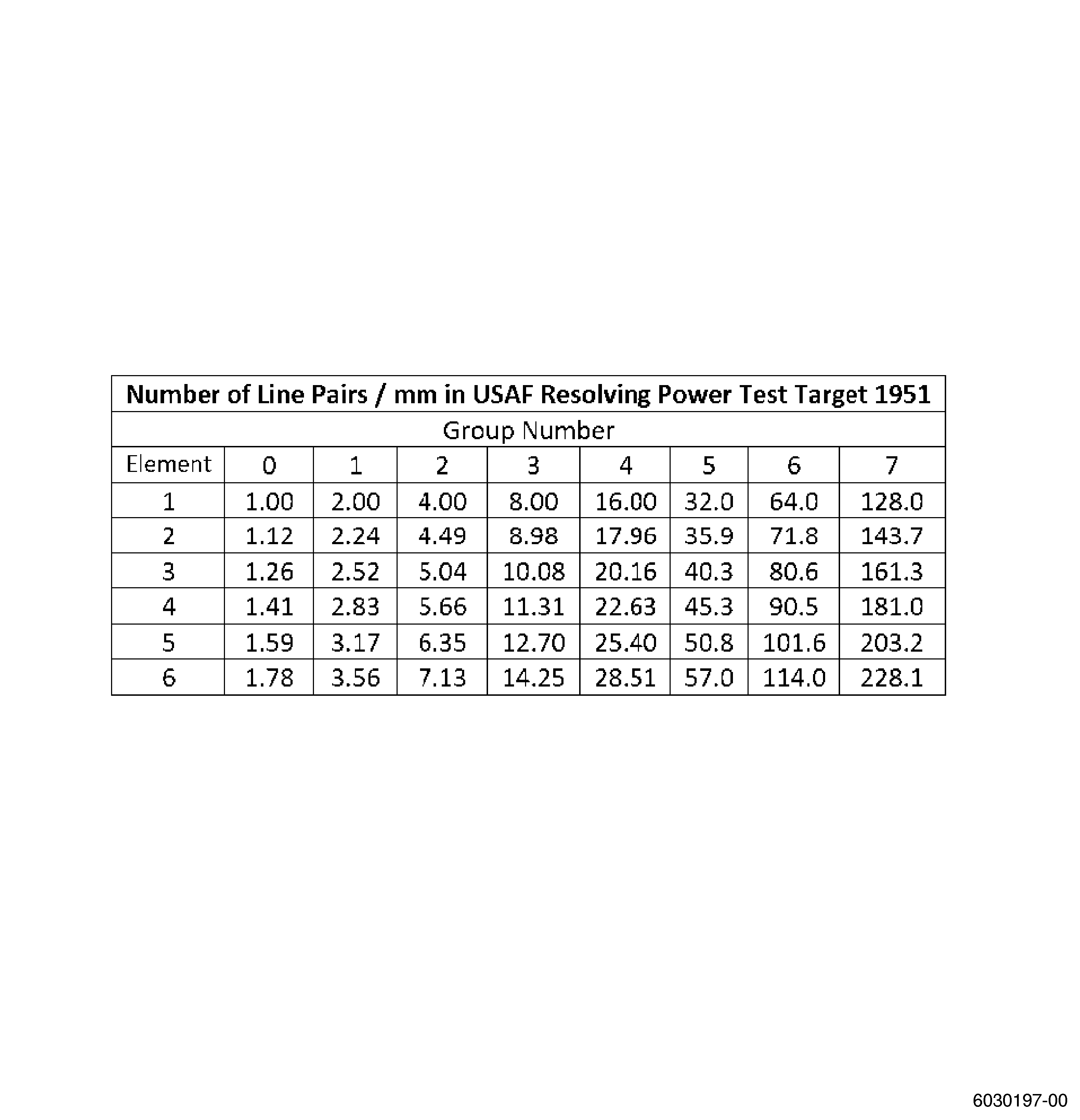
| 4 | The system must be capable of discerning Group I, Element 5 of the 1951 USAF Resolution Target. Refer to Figure 1. The resolution must be given at the specific inspection distance and angle. |
| 5 | Tools or method used to measure florescent indications must be accurate to within +/- 0.002 inch (+/- 0.05 mm). Accuracy validation must be done semi-annually. |
| 6 | The camera must be fixtured in such a manner that the indexing makes sure that there is a 100 percent inspection coverage of all required inspection surfaces. |
| 7 | Successive scan indexes must overlap each other by a minimum of 10 percent of the field of view in the index direction. |
| 8 | The length and the geometry of the system must allow the viewing optics to be positioned within close proximity of the inspection surface as dictated by the field of view and depth of field requirements. |
| 9 | Control of each axis of motion must be provided to maintain a known, fixed viewing distance as well as measurable scan indexing. |
| 10 | Field of view must be established for each inspection. The established field of view must meet USAF 1951 Resolution Target requirement. |
| 11 | UV-A intensity must be tested daily over the entire field of view throughout the entire viewing distance and, if applicable, over the entire system zoom range. |
| 12 | If minimum UV-A intensity cannot be achieved over the entire field of view, the field of view used during the inspection must be limited to an area that will provide for minimum intensity and this useable area must be depicted within the field of view. |
| 13 | Viewing system performance must be checked daily and comparable to un-aided visible results such as TAM panels, fluorescent USAF1951, etc (i.e., color, intensity). Level of fluorescent penetrant must be comparable. |
| 14 | Resolution must be tested normal to the target surface and over the full field of view. If the resolution requirements cannot be met over the full viewing angle, the field of view used during the inspection must be limited to an area that will provide for minimum resolution and this useable area must be depicted within the field of view. |
| a | Prior to first use. |
| b | Annually. |
| c | Any time the repairs have been completed. |
| d | Any time the image quality is suspected of deterioration. |
| 15 | In meeting the performance specification for resolution, not only the specified element must be observed, but individual lines must be clearly resolved (i.e., the lines and spaces must form a distinct pattern with clearly defined edges). |
| 16 | Viewing system resolution must be done daily at the maximum working distance with the target perpendicular to the viewing system and in the center of field of view. |
| 17 | Each mechanical axis used for viewing system and turntable must be checked annually or whenever a component of the system has been repaired or replaced to make sure that the travel accuracy and repeatability are maintained within 5 percent of the minimum field of view. Inspection facilities must generate a quality plan. |
| 18 | Inspection facilities must consider special precautions to make sure that the parts are protected from environmental damage and construction of handling systems must minimize contamination of penetrant materials during the inspection to prevent possible penetrant removal inadvertently. |
| NOTE: |
|
| 19 | To get a list of recommended remote FPI video viewing system, please contact the following for more information: GEAE FST Group; ndttooling@ge.com |
| B. | Quality Control. |
| To control the quality of the fluorescent penetrant inspection process, it is necessary to control the quality of the process, the materials, and the equipment. It is necessary that a quality assurance plan be established to check the process, materials, and equipment to the frequencies that are listed below. It is necessary that the results of the quality control checks be documented. |
| (1) | Perform a process check as follows: |
| (a) | Perform a system or process performance test using a known defect test specimen (KDTS) before or concurrent with the first parts on each shift and after any change in process chemical tanks, maintenance of process equipment, and any period of inactivity. Use the following list of KDTS for the process check: |
| (b) | There shall be one "Working" panel for each penetrant in use and one "Master" panel for each sensitivity level in use and these panels shall be uniquely identified for use with and traceable to the specific penetrant system and sensitivity level penetrant system respectively that it is used to check. |
| (c) | Establish base line data for both working and master panels. The results obtained using known clean working and master panels processed with unused penetrant materials upon their initial use in the system shall be documented. For the PSM-5 Test panel, results shall include both the number of indications visible and the size of the fluorescent indications obtained. The minimum allowable number of crack centers visible for each class of penetrant, when establishing the baseline requirements, shall be as listed below. Background fluorescence on the grit blasted surface of the panel shall be at an acceptable level. Black light photos may be used to evaluate changes in background fluorescence or the fluorescence of the indications. |
|
| (d) | The working panel shall be processed through the penetrant line before or concurrent with the first parts on each shift and shall be compared to the results originally obtained when the base line for the panel and system was established. Results comparable to the base line shall indicate an acceptable penetrant system. If the working panel indicates unacceptable results, the master panel shall be processed using the same parameters. If the master panel indicates acceptable results, the penetrant system shall be considered acceptable and the working panel shall be removed from service. It may be reconditioned or replaced. If the master panel indicates unacceptable results, the penetrant system shall be considered unacceptable and shall not be used until the necessary corrections have been made. All parts processed since the last acceptable panel results shall be cleaned and reprocessed in an acceptable penetrant system. |
| (e) | All in use panels shall be checked monthly for degradation of sensitivity. Panel processing parameters shall be the same as those used for establishing the base line results, with special attention to equal developer dwell times. Measurement of fluorescent indication sizes obtained shall be compared to the base line indication sizes. This may be done using the calibrated FPI feeler gage or gage pins, callipers or verniers. A deviation of more than 30 percent from the original indication size shall be considered unacceptable and the panel shall be removed from service. The panel may be reconditioned or replaced. |
| (f) | Clean and store the KDTS in accordance with the manufacturer's recommended practice. |
| (g) | If the process is determined to be out of control by the KDTS, reinspect all engine hardware inspected since the last in control point. |
| (2) | Perform the material checks as follows: |
| NOTE: |
|
| (a) | Check the dry developer daily as follows: |
| 1 | Apply dry developer to a 4-inch diameter circle into a thin layer on a flat surface, using the same mean used to apply developer to hardware being inspected. |
| 2 | Examine the powder under ultraviolet light for fluorescent contamination. |
| NOTE: |
|
| 3 | If ten or more fluorescent specks are observed in the working batch, discard the working batch. |
| 4 | Visually examine the working batch of developer for evidence of moisture. |
| 5 | If the developer is not fluffy and finely divided or if it tends to cake or lumps are present, discard the developer. |
| (b) | Check the wet developer daily as follows: |
| 1 | Immerse a clean part in the developer. |
| 2 | Upon removal, check the part to ensure that it is evenly wetted and that there is no evidence of beading, broken film, or drawback. |
| 3 | Check the part under ultraviolet light. |
| 4 | If the developer on the part shows evidence of fluorescence, discard the developer. |
| 5 | Verify the specific gravity per the appropriate solution sheet. |
| 6 | Concentration shall be checked weekly with a hydrometer and shall be in accordance with the developer Supplier's recommended concentration. |
| (c) | On a weekly basis, check the concentration of the hydrophilic remover with a refractometer. |
| 1 | Refer to paragraph 2.C., for the maximum allowable concentrations. |
| 2 | Variation of concentration greater than three percentage points from the initial, unused concentration or, concentration exceeding that listed in QPL-AMS 2644 for the system and products used is unsatisfactory. In no case shall the concentration exceed the maximum concentration listed in QPL-AMS-2644 for immersion application. Spray concentrations shall be checked weekly with the refractometer and shall not exceed the initial concentration for the system. In no case shall the concentration exceed 5 percent for spray application. |
| (d) | Check the working bath penetrant for fluorescent brightness quarterly per the requirements of ASTM E1135. |
| 1 | Brightness tests of in-use penetrants shall be conducted in accordance with Test Method E 1135 with a sample of the unused penetrant serving as the reference. Brightness values less than 90 percent of the unused penetrant brightness are unsatisfactory and the in-use penetrant shall be discarded or otherwise corrected, as appropriate. |
| 2 | If using a water washable penetrant in an immersion application, or if spray application is not spray to waste, Classes A, B, or C, analyze the water content at least monthly per ASTM D95 or ASTM E203. |
| NOTE: |
|
| NOTE: |
|
| (3) | Perform equipment checks as follows: |
| WARNING: |
|
| (a) | Daily, check the ultraviolet light source used for inspection to ensure that it has an intensity of no less than 1200 microwatts per square centimeter when measured at 15 inches (38 cm). |
| NOTE: |
|
| NOTE: |
|
| (b) | Daily, check the background white light in the inspection area to ensure that the white light does not exceed two foot-candles (21.5 lx). |
| (c) | Daily, check the white light emitted from the UV light source used for inspection to ensure that it does not exceed two foot-candles (21.5 lx). |
| (d) | On a semi-annual basis (except for the dryer oven which shall be checked quarterly), do the following: |
| 1 | Check the pressure and temperature gauges and the timers used in the process for accuracy in accordance with a system approved by the appropriate air authority. |
| 2 | Survey the drying oven to assure that proper temperatures are being maintained in the areas of the oven that are being used to dry parts per AMS 2647. |
| 3 | Check the blacklight and whitelight meters. |
| CAUTION: |
|
| (e) | Daily, check LED UV source used for inspection to ensure all diode elements are operational. If any diode is not found operational, the condition shall be corrected or the unit replaced. The operation check should be performed by placing a white sheet of paper in front of the lamp filter and viewing the transmitted light from each diode. |
| C. | Acceptability of Penetrant Systems and Related Materials. |
| (1) | Penetrant systems and products which are acceptable for use in inspecting engine components are identified for each respective inspection class. |
| (2) | A system of penetrant and hydrophilic remover from a single manufacturer must be used when a post-emulsifiable system is specified. |
| (3) | Any developer or solvent may be used with any one specific penetrant system. |
| (4) | Personnel Requirements. |
| (a) | Personnel performing this inspection must be certified in accordance with National Aerospace Standard 410 (NAS 410), American Society of Non-Destructive Testing specification ASNT-TC-1A (ASNT-TC-1A), Air Transport Association of America specification 105 (ATA 105), or a locally approved certification program. |
| (b) | Personnel performing this inspection should receive practical training in the use of this procedure and must demonstrate proficiency in use and control of inspection equipment, inspection of hardware, and evaluation of indications before the authority to accept and reject hardware is delegated. |
| (c) | Any training which may be provided by General Electric for a technique requiring the performance of this inspection method does not imply that the personnel who receive that training have met the requirements for inspector certification in accordance with NAS 410, ASNT-TC-1A, or ATA 105. |
| D. | Supplemental Documentation. |
| Aerospace Materials Specification AMS 2647. |
| Measurement of Emission Characteristics and Requirements for LED UV-A Lamps Used in Fluorescent Penetrant and Magnetic Particle Testing ASTM E3022. |
| NOTE: |
|
| 2 . | Definitions. |
| Subtask 70-32-02-230-011 |
| A. | Inspection Sensitivity Levels. Inspection processes are categorized according to type of process with class and degree of sensitivity required. As inspection requirements become more critical, more sensitive material and processes are used. The specific class designated refers to method of penetrant application and indicates penetrant dwell times, emulsification and developer requirements. |
| (1) | The following table cross-references GEAE Commercial Standard Practice FPI classifications to the commercial standard SAE AMS 2644 and the QPL-AMS-2644-QPD. |
| (2) | Qualified Products listed in QPL-AMS-2644-QPD (Qualified Products Database) are considered acceptable alternate products to those listed in this process document. Use the following table as a cross reference for Commercial Specification Method/Sensitivity to GEAE Class. |
|
| (3) | The following are industry standard definitions applying to penetrant inspection. |
| (a) | Type 1 is fluorescent dye. |
| (b) | Methods. |
| 1 | Method A is water-washable. |
| 2 | Method D is post-emulsifiable, hydrophilic. |
| (c) | Sensitivity Levels. |
| 1 | Level 2 - Medium |
| 2 | Level 3 - High |
| 3 | Level 4 - Ultrahigh |
| NOTE: |
|
| (4) | It is acceptable to substitute a penetrant of higher sensitivity within the same classification (e.g., substitute a level 3 or 4 water washable penetrant for a level 2) provided the following requirements are met. |
| (a) | Higher sensitivity penetrant shall not result in excessive background fluorescence that could adversely affect the quality of the inspection. |
| (b) | Known defect test specimens referenced in paragraph 1.B.(1)(a) shall meet the requirements for the higher sensitivity inspection. |
| (5) | Application of Penetrant. |
| (a) | Classes A, C, D, and G. |
| Apply the penetrant by immersion, brushing, or spraying. All surfaces to be examined shall be completely covered. |
| (b) | Class B. |
| Apply the penetrant by spraying. All surfaces to be examined shall be completely covered. Class B is used where immersion application will cause penetrant entrapment problems. |
| (6) | Penetrant Dwell Time. |
| (a) | Classes A and B: 15 minutes minimum. |
| (b) | Classes C, D, and G: 30 minutes minimum. |
| (7) | Emulsification Contact Time. |
| NOTE: |
|
| (a) | Contact time shall not exceed 2 minutes unless otherwise specified in the engine shop manuals. |
| (8) | Developing Time. |
| (a) | Classes A, B, C, D, and G: 10 minutes minimum for dry powder or water mixed developers. |
| (b) | Classes A, B, C, D, and G: 10 minutes minimum for non-aqueous wet developers (NAWD). |
| B. | Emulsifier (Lipophilic Emulsifier). |
| No longer used on engine hardware |
| C. | Remover (Hydrophilic Remover). |
| Removers are mixtures composed of surface active agents together with additives capable of dilution up to many times their volume in water to form aqueous solutions that are stable, nontoxic, and noncorrosive. These solutions are mutually insoluble with the penetrant. The hydrophilic remover concentration shall not exceed 5 percent when applied by spraying and the maximum concentration listed in the QPL-AMS-2644 when applied by immersion. |
| D. | Methods of Application. |
| (1) | Immersion. |
| The inspection material is applied by placing the part into a tank containing the inspection material so that all surfaces of the part to be inspected are in contact with the inspection material. |
| (2) | Spraying. |
| The inspection material is directed under pressure, in the form of droplets or as a mist, onto the surfaces of the part to be inspected. |
| (3) | Brushing. |
| The inspection material is applied with a brush to the surfaces of the part to be inspected. Brush application is only allowed for penetrant application. |
| (4) | Flowing. |
| The inspection material is applied as a liquid stream from a hose or by pouring from a container to flow over the surfaces of the part to be inspected. |
| (5) | Bleedback Technique. |
| Each of the following sections contains instructions on how to evaluate FPI indications utilizing solvent wipe and re-application developer. The process will vary depending on the type of developer used and the time allowed for the re-development, however this process is known as Bleedback Technique and is often referred to in the process documents. |
| (6) | Sizing. |
| Measure relevant indications after completing the bleedback technique defined in 2.D.(5). |
| E. | General Definitions. |
| (1) | Indication - The total area of fluorescence, created as a result of penetrant bleedout from a discontinuity visible when viewed under black light. |
| (2) | Linear Indication - Any indication with a length to width ratio of 3 to 1 or greater. |
| (3) | Relevant Indication - All indications other than those determined to be non-relevant. |
| (4) | Non-relevant Indication - A NDE indication which does not reappear after solvent wipe process (bleedback process), or is caused by mechanical retention of penetrant from a component feature such as a rivet, pressfit, or fastener. |
| (5) | Microshrinkage Evaluation - Remove developer from the surface. Wipe once with solvent using a dampened cotton swab or camel's hair brush. Evaluate the microshrinkage as soon as the solvent has dried (Do not reapply developer). Compare the indication with those shown on GEAE Photo Standard 8311253 to determine the class of microshrinkage. |
| 3 . | Class A, B, C (Water-Washable). |
| Subtask 70-32-02-230-012 |
| A. | General. |
| (1) | This is a water-washable, medium sensitivity fluorescent penetrant inspection process. The method of penetrant application (immersion, spraying, brushing, or flowing) depends on the size and configuration of the part being inspected. Immersion method is preferred except when parts have areas where penetrant may become entrapped. |
| (2) | Titanium alloy and Marage 250 parts are subject to stress corrosion cracking when residues of halogen containing compounds remain on a part that is subsequently subjected to elevated temperatures typical of welding, heat treating, or engine operation. These parts must be thoroughly cleaned with nonhalogen compounds after exposure to any halogen-containing compound to prevent the cracking and possible failure of parts. |
| (3) | Observe the following. |
| (a) | Parts must be thoroughly cleaned and dried before being subjected to inspection process to accomplish a proper inspection and to prevent contamination of the inspection materials. |
| (b) | Penetrant inspection shall always precede magnetic-particle inspection when both inspections are required. |
| (c) | Plug or cap all tubes and holes, in the part being inspected, to prevent inspection materials from being entrapped. |
| (d) | Measures shall be taken to verify complete coverage of all areas to be inspected. |
| (e) | Fluorescent penetrants and developers may be from different manufactures. |
| (f) | If automatic or mechanized inspection processing systems are to be used, they should control the process in such a manner that defect detectability is equivalent to manual operations. |
| B. | Equipment. |
| (1) | Tanks for penetrants. Tanks should have the following. |
| (a) | Construction of noncorrosive materials. |
| (b) | Drain racks and splash guards to prevent contamination of adjacent tanks. |
| (c) | Covers to protect contents when not in use. |
| (d) | Identification sign for the material name, batch number, and date of implementation for each tank. |
| (2) | Spray booths for penetrants when materials are applied by spray. Spray booths should have the following. |
| (a) | Adequate exhaust provisions to prevent breathing of vapors by operators, and accumulation of flammable penetrant mists. |
| (b) | Construction that will prevent contamination of process materials and nearby parts being processed. |
| (3) | Dust chamber for applying dry developer. |
| (4) | Water system to provide washing and rinsing water. Water system should have the following. |
| (a) | Water at ambient temperature. |
| (b) | Hose and spray nozzle to provide directed flow of water as course droplets in a diffuse pattern. |
| (c) | Water pressure at spray nozzle to be approximately 30 psi (207 kPa). Pressure should not exceed 40 psi (276 kPa). If necessary, it is acceptable to add filtered air supply to nozzle to obtain a spray. Air pressure is not to exceed 25 psi (172 kPa). |
| (5) | Penetrant removal should take place in a suitably darkened area fitted with an ultraviolet lamp to check the effectiveness of water washing. |
| (6) | Compressed air supply for removing excess or pooled water prior to oven drying. Air supply must have filters to remove oil and moisture which can contaminate parts or inspection materials. Air pressure shall not exceed 25 psi (172 kPa). Suction may also be used to remove excess or trapped water. |
| (7) | Circulating hot air dryer. The dryer should have the following. |
| (a) | The oven shall not exceed 160°F (71°C) and shall maintain uniform temperature. The temperature indicator shall be accurate to plus or minus 10°F (plus or minus 5.6°C) of the actual oven temperature. The temperature controller shall be accurate to plus or minus 15°F (plus or minus 8.3°C) of the set point. |
| (b) | Indicating device for air temperature. |
| (8) | Inspection booth or darkroom which prevents excessive admission of white light. Excessive white light will interfere with detection of indications. |
| CAUTION: |
|
| (9) | Ultraviolet lamp to detect fluorescent indications. |
| (10) | White light lamp for visual inspection of parts. The lamp should be capable of providing a minimum of 100 ft-candles (1076 lx) of white light at the inspection surface. |
| (11) | Time controls for each operation. Controls may be: |
| (a) | Automatic devices. |
| (b) | Timers with alarms. |
| (12) | Tools for inspection personnel. Tools should consist of at least the following. |
| (a) | 3X or 5X, and 10X magnifying lens. |
| (b) | Assorted adjustable mirrors. |
| (c) | Size of indication shall be determined through the use of calibrated feeler gages or calibrated pin gages with an accuracy of plus or minus 0.002 inch (plus or minus 0.005 cm). These will be placed directly over the indication to assess size. The smallest feeler gage/pin gage that completely covers the indication will be used to determine size. Gage sizes must be within plus or minus 0.0025 inch (plus or minus 0.0064 cm) of acceptance criteria. |
| (d) | Cotton swabs and absorbent cotton or paper material to apply solvent for evaluating fluorescent indications. |
| (e) | Bulb-type applicator for dry developer when evaluating fluorescent indications. Non-aqueous wet developer may be used in place of dry powder. |
| C. | Materials. All materials are used at ambient temperature. The following materials may be used for this class of inspection: |
| (1) | Class A, B, and C water washable penetrant inspection systems as follows: |
| Approved products for this inspection process are in Qualified Products Database QPL-AMS-2644-QPD. QPD is available from ASSIST-Acquisition Streamlining and Standardization Information System. Refer to the List of Suppliers in Step 4 of 70-80-00. |
| For this class of inspection, only use the approved materials that follow: |
| Type I - Fluorescent Dye |
| Method A - Water Washable |
| Sensitivity Level 2 - Medium |
| NOTE: |
|
| CAUTION: |
|
| (2) | Solvents as follows: |
|
| WARNING: |
|
| CAUTION: |
|
| D. | Procedure. |
| NOTE: |
|
| (1) | Application of Penetrant. |
| WARNING: |
|
| (a) | Apply penetrant by immersion, spraying, brushing, or flowing. Immersion is preferred except when parts have areas where penetrant may be entrapped. |
| (b) | Allow a minimum of 15 minutes (Class A or B), or 30 minutes (Class C), for penetration before water washing. |
| NOTE: |
|
| (c) | Remove penetrant from surface of part by spray washing with water. Water pressure shall not exceed 40 psi (276 kPa). |
| (d) | Observe part under ultraviolet light to make sure excess penetrant has been removed. |
| NOTE: |
|
| (e) | If excessive fluorescent background is present, continue spray wash until clean or until it is evident that the background cannot be removed; reclean, and reprocess the part. |
| NOTE: |
|
| (f) | Position parts to allow excess water to drain, and if necessary, rotate or shake part to aid removal of entrapped water. |
| (g) | If necessary, remove any remaining water by blowing with dry air at a maximum pressure of 25 psi (172 kPa), by siphoning, or by blotting with clean, lint-free towels. |
| (h) | Dry the parts by placing them in a circulating hot air dryer. Do not allow parts to remain in dryer any longer than necessary to remove moisture. The dryer temperature should not exceed 160°F (70°C). |
| (2) | Application of Dry Developer. |
| WARNING: |
|
| (a) | Apply dry developer to a dry part so that all areas to be inspected are completely covered with a light coating of developer. |
| (b) | Allow a minimum of 10 minutes for developer to absorb penetrant before inspecting parts. |
| NOTE: |
|
| NOTE: |
|
| (3) | Application of non-aqueous wet developer when required by a process document. |
| NOTE: |
|
| NOTE: |
|
| WARNING: |
|
| (a) | Spray a fine thin coating by holding nozzle about 8-10 inches (200-250 mm) from surface. Normally, two passes over same area are required. Coverage should be uniform and light enough so metallic surface background is visible through developer coating. |
| NOTE: |
|
| (b) | Allow a minimum of 10 minutes for developer to absorb penetrant before inspecting parts. |
| NOTE: |
|
| (4) | Inspection of Parts. |
| NOTE: |
|
| (a) | Direct ultraviolet light on part while in inspection booth or darkroom. |
| (b) | Inspect to limits specified for the part. |
| (c) | If no limits are specified in the process document, contact your GEAE representative to request the definition of FPI acceptability limits. |
| (d) | Inspect fluorescent indications as follows: |
| NOTE: |
|
| WARNING: |
|
| 1 | Wipe area once with a solvent listed in Step 3.C., using a cotton swab or absorbent material. |
| NOTE: |
|
| 2 | Inspect under ultraviolet light. If the indication reappears as non-linear, measure the resulting indication without redeveloping. If the indication reappears as linear and is rejectable in size, the part may be rejected before the full development time has elapsed. Otherwise, reapply dry or non-aqueous wet developer. Redevelopment time shall be a minimum of 10 minutes before re-evaluation of the indication. |
| 3 | Indications that reappear within 10 minutes shall be considered as relevant indications. |
| 4 | If indications do not reappear, the original indication is considered non-relevant. Inspect the part under white light using a magnifying lens to determine if there is a source of retention of penetrant. |
| (e) | Indications (cracks) extending through a part can be detected by applying the penetrant to one surface and applying the developer to the other surface. |
| (f) | Identify locations of defects using an approved marking method. |
| (5) | Cleaning of Parts After Inspection. |
| CAUTION: |
|
| CAUTION: |
|
| (a) | Unless otherwise directed, all parts shall be cleaned to remove any retained penetrant and developer as soon after inspection as practicable. |
| WARNING: |
|
| (b) | Any penetrant or developer may be removed by light duty aqueous cleaning (TASK 70-21-22-110-042, Cleaning Method No. 22 - Light Duty Aqueous Cleaning), steam cleaning (TASK 70-21-03-160-001, Cleaning Method No. 3 - Steam Cleaning), or washing with warm water. |
| (c) | Make sure that all internal passages and recesses are completely flushed. Remove large pockets of water by rotating or shaking the part. Blow out passages and cavities with dry air. |
| E. | Quality Assurance. |
| (1) | Assure that all process and acceptability tests listed in 1.B., Quality Control, have been completed and documented prior to processing parts. |
| (2) | Following inspection, check part under ultraviolet light to make sure all penetrant material has been removed. |
| (3) | Assure that residues of processing compounds are completely removed from titanium and titanium alloy parts. |
| 4 . | Class A, B, C (Post-Emulsifiable). |
| Subtask 70-32-02-230-013 |
| A. | General. |
| (1) | This is a post-emulsifiable, medium sensitivity fluorescent penetrant inspection process. The method of penetrant application (immersion, spraying, brushing, or flowing) depends on the size and configuration of the part being inspected. Immersion method is preferred except when parts have areas where penetrant may become entrapped. |
| (2) | Titanium alloy parts are subject to stress corrosion cracking when residues of halogen containing compounds remain on a part that is subsequently subjected to elevated temperatures typical of welding, heat treating, or engine operation. These parts must be thoroughly cleaned with nonhalogen compounds after exposure to any halogen containing compound to prevent the cracking and possible failure of parts. |
| (3) | Removers are gradually contaminated with penetrant during use. Therefore, they must periodically be compared to a retained standard sample. Every time a new mixture of remover is prepared, a master sample shall be obtained and kept as an standard sample for comparison test purposes. If increased fluorescent background is observed on parts or KDTS, remover should be changed. |
| (4) | Penetrant inspection shall always precede magnetic-particle inspection when both inspections are required. |
| (5) | Fluorescent penetrants, and hydrophilic removers used together in an inspection process should be the products of one manufacturer. Developers supplied by other manufacturers may be used in this process. |
| (6) | If automatic or mechanized inspection processing systems are to be used, they should control the process in such a manner that defect detectability is equivalent to manual operations. |
| B. | Equipment. |
| (1) | Tanks for penetrants, removers, and wet developers. Tanks should have the following. |
| (a) | Construction of noncorrosive materials. |
| (b) | Drain racks and splash guards to prevent contamination of adjacent tanks. |
| (c) | Covers to protect contents when not in use. |
| (d) | Identification sign for material name, batch number, and date of implementation for each tank. |
| (e) | Agitator (air, motor driven propeller, or pumping system) for hydrophilic remover tank and suspension type water-wet developer tank. |
| (2) | Spray booths for penetrants, remover and water-wet developers when materials are applied by spray. Spray booths should have the following. |
| (a) | Adequate exhaust provisions to prevent breathing of vapors by operators, and accumulation of flammable penetrant mists. |
| (b) | Construction that will prevent contamination of process materials and nearby parts being processed. |
| (3) | Dust chamber for applying dry developer. |
| (4) | Water system to provide washing and rinsing water. Water system should have the following. |
| (a) | Water at ambient temperature. |
| (b) | Hose and spray nozzle to provide directed flow of water as course droplets. |
| (c) | Water pressure at spray nozzle to be approximately 30 psi (207 kPa). Pressure should not exceed 40 psi (276 kPa). If necessary, it is acceptable to add filtered air supply to nozzle to obtain a spray. Air pressure is not to exceed 25 psi (172 kPa). |
| (d) | Penetrant removal should take place in a suitably darkened area fitted with an ultraviolet lamp to check the effectiveness of water washing. |
| (5) | Compressed air supply for removing excess or pooled water prior to oven drying. Air supply must have filters to remove oil and moisture which can contaminate parts or inspection materials. Air pressure shall not exceed 25 psi (172 kPa). Suction may also be used to remove excess or trapped water. |
| (6) | Circulating hot air dryer. The dryer should have the following: |
| (a) | The oven shall not exceed 160°F (71°C) and shall maintain uniform temperature. The temperature indicator shall be accurate to plus or minus 10°F (plus or minus 5.6°C) of the actual oven temperature. The temperature controller shall be accurate to plus or minus 15°F (plus or minus 8.3°C) of the set point. |
| (b) | Indicating device for air temperature. |
| (7) | Inspection booth or darkroom which prevents excessive admission of white light. Excessive white light will interfere with detection of indications. |
| CAUTION: |
|
| (8) | Ultraviolet lamp to detect fluorescent indications. |
| (9) | White light lamp for visual inspection of parts. The lamp should be capable of providing a minimum of 100 foot-candles (1076 lx) of light at the inspection surface. |
| (10) | Time controls for each operation. Control may be: |
| (a) | Automatic devices. |
| (b) | Timers with alarms. |
| (11) | Tools for inspection personnel. Tools should consists of at least the following. |
| (a) | 3X or 5X, and 10X magnifying lenses. |
| (b) | Assorted adjustable mirrors. |
| (c) | Size of indication shall be determined through the use of calibrated feeler gages or calibrated pin gages with an accuracy of plus or minus 0.002 inch (plus or minus 0.005 cm). These will be placed directly over the indication to assess size. The smallest feeler gage/pin gage that completely cover the indication will be used to determine size. Gage sizes must be within plus or minus 0.0025 inch (plus or minus 0.0064 cm) of acceptance criteria. |
| (d) | Cotton swabs, absorbent cotton or paper towels to apply solvent for evaluating fluorescent indications. |
| (e) | Bulb-type applicator for dry developer when evaluating fluorescent indications. |
| C. | Materials. The following materials may be used for this class of inspection: |
| (1) | Class A, B, and C post-emulsifiable penetrant inspection systems as follows: |
| Approved products for this inspection process are in Qualified Products Database QPL-AMS-2644-QPD. QPD is available from ASSIST-Acquisition Streamlining and Standardization Information System. Refer to the List of Suppliers in Step 4 of 70-80-00. |
| For this class of inspection, only use the approved materials that follow: |
| Type I - Fluorescent Dye |
| Method D - Post-emulsifiable, Hydrophilic |
| Sensitivity Level 2 - Medium |
| NOTE: |
|
| NOTE: |
|
| CAUTION: |
|
| (2) | Solvents as follows: |
|
| WARNING: |
|
| D. | Procedure. |
| NOTE: |
|
| (1) | Application of Penetrant. |
| WARNING: |
|
| (a) | Apply penetrant by immersion, spraying, brushing, or flowing. Immersion is preferred except when parts have areas where penetrant may be entrapped. |
| (b) | Allow a minimum of 15 minutes (Class A or B), or 30 minutes (Class C), for penetration before removing excess penetrant. |
| NOTE: |
|
| (2) | Removal of Excess Penetrant Using Hydrophilic Remover. |
| (a) | Prerinse the part with water spray to remove loosely held excess penetrant. The recommended water pressure is 30 psi (210 kPa). Do not exceed 40 psi (276 kPa). Spray rinse until part is relatively free of penetrant as observed under a blacklight. |
| (b) | Reposition or tilt part as required to aid draining excess water. Remove any large pockets of water by siphoning. |
| (c) | Apply remover by spraying or immersion. If immersion is used, immerse the part in mildly agitated remover. If spraying is used, wet continuously. Use minimum contact time to remove background fluorescence without removing defect indications. Do not exceed 2 minutes maximum total contact time. |
| NOTE: |
|
| (d) | Rinse part with water to stop emulsification process by immersion or spraying. Immersion is preferred for accurate control of contact time. |
| (e) | Water wash parts using water to remove remaining penetrant and remover. Use water at or about 30 psi (210 kPa). Water pressure shall not exceed 40 psi (276 kPa). |
| (f) | Check part under ultraviolet light to make sure background fluorescence, which would interfere with inspection, is not present. If caused by remover, repeat water wash of the area. If excessive background fluorescence is caused by penetrant, clean the part completely and reprocess it. |
| (g) | Position part to allow excess water to drain and if necessary, rotate or shake the part. Remove entrapped water by siphoning, by blowing with dry air, or by blotting with clean, lint-free towels. |
| CAUTION: |
|
| (h) | Dry the parts by placing them in a circulating hot air dryer. Do not allow parts to remain in dryer any longer than necessary to remove moisture. The temperature shall not exceed 160°F (70°C). |
| (3) | Application of Developer. |
| (a) | Dry Developer Application. |
| WARNING: |
|
| 1 | Apply dry developer to a dry part so that all areas to be inspected are completely covered with a light coating of developer. |
| 2 | Allow a minimum of 10 minutes for developer to absorb penetrant before inspecting parts. |
| NOTE: |
|
| NOTE: |
|
| (b) | Application of non-aqueous wet developer when required by process document. |
| NOTE: |
|
| NOTE: |
|
| WARNING: |
|
| 1 | Spray a fine thin coating by holding nozzle about 8-10 inches (200-250 mm) from surface. Normally two passes over same area are required. Coverage should be uniform and light enough so metallic surface background is visible through developer coating. |
| NOTE: |
|
| 2 | Allow a minimum of 10 minutes for developer to absorb penetrant before inspecting parts. |
| NOTE: |
|
| (4) | Inspection of Parts. |
| NOTE: |
|
| (a) | Direct ultraviolet light on part while in inspection booth or darkroom. |
| (b) | Inspect to limits specified for the part. |
| (c) | If limits are not specified by the process document, contact your GEAE representative to request the definition of FPI acceptability limits. |
| (d) | Inspect fluorescent indications as follows: |
| NOTE: |
|
| WARNING: |
|
| 1 | Wipe area once with a solvent listed in Step 4.C., using a cotton swab or absorbent material. |
| NOTE: |
|
| 2 | Inspect under ultraviolet light. If the indication reappears as non-linear, measure the resulting indication without redeveloping. If the indication reappears as linear and is rejectable in size, the part may be rejected before the full development time has elapsed. Otherwise, reapply dry or Non-aqueous Wet Developer. Redevelopment time shall be a minimum of 10 minutes before re-evaluation of the indication. |
| 3 | Indications that reappear within 10 minutes shall be considered as relevant indications. |
| 4 | If indications do not reappear, the original indication is considered non-relevant. Inspect the part under white light using a magnifying lens to determine if there is a source of retention of penetrant. |
| (e) | Indications (cracks) extending through a part can be detected by applying the penetrant on one surface and applying the developer to the other surface. |
| (f) | Identify locations of defects using an approved marking method. |
| (5) | Cleaning of Parts After Inspection. |
| CAUTION: |
|
| CAUTION: |
|
| (a) | Unless otherwise directed, all parts shall be cleaned to remove any retained penetrant and developer as soon after inspection as practicable. |
| WARNING: |
|
| (b) | Dry powder or non-aqueous wet developers may be removed by light duty aqueous cleaning (TASK 70-21-22-110-042 , Cleaning Method No. 22 - Light Duty Aqueous Cleaning), steam cleaning (TASK 70-21-03-160-001, Cleaning Method No. 3 - Steam Cleaning), or washing with warm water. |
| (c) | If penetrant is present, the part must be processed through an emulsifier/remover solution, through a vapor degreaser, or soaked in an approved solvent and then washed with warm water. |
| (d) | Make sure that all internal passages and recesses are completely flushed. Remove large pockets of water by rotating or shaking the part. Blow out passages and cavities with dry air. |
| E. | Quality Assurance. |
| (1) | Assure that all process and acceptability tests listed in 1.B., Quality Control, have been completed and documented prior to processing parts. |
| (2) | Following inspection, check part under ultraviolet light to make sure all penetrant material has been removed. |
| (3) | Assure that residues of processing compounds are completely removed from titanium and titanium alloy parts. |
| 5 . | Class D (Post-Emulsifiable). |
| Subtask 70-32-02-230-014 |
| A. | General. |
| (1) | This is a post-emulsifiable, high sensitivity fluorescent penetrant inspection process. It uses a penetrant, remover, and a dry developer. The method of penetrant application (immersion, spraying, brushing, or flowing) depends on the size and configuration of the part being inspected. Immersion method is preferred except when parts have areas where penetrant may become entrapped. |
| (2) | Titanium alloy parts are subject to stress corrosion cracking when residues of halogen containing compounds remain on a part that is subsequently subjected to elevated temperatures typical of welding, heat treating, or engine operation. These parts must be thoroughly cleaned with nonhalogen compounds after exposure to any halogen containing compound to prevent the cracking and possible failure of parts. |
| (3) | The remover is gradually contaminated with penetrant during use. Therefore, it must periodically be compared to a retained standard sample. Every time a new mixture of remover is prepared, a master sample shall be obtained and kept as a standard sample for comparison test purposes. If increased fluorescent background is observed on parts or KDTS, remover should be changed. |
| (4) | Observe the following. |
| (a) | Parts must be thoroughly cleaned and dried before being subjected to the inspection process to accomplish a proper inspection and to prevent contamination of the inspection materials. |
| (b) | Penetrant inspection shall always precede magnetic-particle inspection when both inspections are required. |
| (c) | Plug or cap all tubes and holes, in the part being inspected, to prevent inspection materials from being entrapped. |
| (d) | Fluorescent penetrants and removers used together in an inspection process should be the products of one manufacturer. The developer may be supplied by another manufacturer. |
| (e) | If automatic or mechanized inspection processing systems are to be used, they should control the process in such a manner that defect detectability is equivalent to manual operations. |
| B. | Equipment. |
| (1) | Tanks for penetrants, and removers. Tanks should have the following. |
| (a) | Construction of noncorrosive materials. |
| (b) | Drain racks and splash guards to prevent contamination of adjacent tanks. |
| (c) | Covers to protect contents when not in use. |
| (d) | Identification sign for material name, batch number, and date of implementation for each tank. |
| (e) | Agitator (air, motor-driven propeller, or pumping system) for hydrophilic remover tank. |
| (2) | Spray booths for penetrants, remover and water-wet developers when materials are applied by spray. Spray booths should have the following. |
| NOTE: |
|
| (a) | Adequate exhaust provisions to prevent breathing of vapors by operators, and accumulation of flammable penetrant mists. |
| (b) | Construction that will prevent contamination of process materials and nearby parts being processed. |
| (3) | Dust chamber for applying dry developer. |
| (4) | Water system to provide washing and rinsing water. Water system should have the following. |
| (a) | Water at ambient temperature. |
| (b) | Hose and spray nozzle to provide directed flow of water as droplets or mist. |
| (c) | Water pressure at spray nozzle to be approximately 30 psi (207 kPa). Pressure should not exceed 40 psi (276 kPa). If necessary, it is acceptable to add filtered air supply to nozzle to obtain a spray. Air pressure is not to exceed 25 psi (172 kPa). |
| (d) | Penetrant removal should take place in a suitably darkened area fitted with an ultraviolet lamp to check the effectiveness of water washing. |
| (5) | Circulating hot air dryer. The dryer should have the following. |
| (a) | The oven shall not exceed 160°F (71°C) and shall maintain uniform temperature. The temperature indicator shall be accurate to plus or minus 10°F (plus or minus 5.6°C) of the actual oven temperature. The temperature controller shall be accurate to plus or minus 15°F (plus or minus 8.3°C) of the set point. |
| (b) | Indicating device for air temperature. |
| (6) | Inspection booth or darkroom which prevents excessive admission of white light. Excessive white light will interfere with detection of a rejectable size indication. |
| (7) | Compressed air supply for removing excess or pooled water prior to oven drying. Air supply must have filters to remove oil and moisture which can contaminate parts or inspection materials. Air pressure shall not exceed 25 psi (172 kPa). Suction may also be used to remove excess or trapped water. |
| CAUTION: |
|
| (8) | Ultraviolet lamp to detect fluorescent indications. |
| (9) | White light lamp for visual inspection of parts. The lamp should be capable of providing a minimum of 100 foot-candles (1076 lx) of white light at the inspection surface. |
| (10) | Time controls for each operation. Controls may be: |
| (a) | Automatic devices. |
| (b) | Timers with alarms. |
| (11) | Tools for inspection personnel. Tools should consist of at least the following. |
| (a) | 3X or 5X, and 10X magnifying lenses. |
| (b) | Assorted adjustable mirrors. |
| (c) | Size of indication shall be determined through the use of calibrated feeler gages or calibrated pin gages with an accuracy of plus or minus 0.002 inch (plus or minus 0.005 cm). These will be placed directly over the indication to assess size. The smallest feeler gage/pin gage that completely covers the indication will be used to determine size. Gage sizes must be within plus or minus 0.0025 inch (plus or minus 0.0064 cm) of acceptance criteria. |
| (d) | Cotton swabs and absorbent paper or cotton towels to apply solvent for evaluating fluorescent indications. |
| (e) | Bulb-type applicator for dry developer or non-aqueous wet developer when evaluating fluorescent indications. |
| C. | Materials. The following materials may be used for this class of inspection: |
| (1) | Class D post-emulsifiable penetrant inspection systems as follows: |
| Approved products for this inspection process are in Qualified Products Database QPL-AMS-2644-QPD. QPD is available from ASSIST-Acquisition Streamlining and Standardization Information System. Refer to the List of Suppliers in Step 4 of 70-80-00. |
| For this class of inspection, only use the approved materials that follow: |
| Type I - Fluorescent Dye |
| Method D - Post-emulsifiable, Hydrophilic |
| Sensitivity Level 3 - High |
| NOTE: |
|
| NOTE: |
|
| CAUTION: |
|
| (2) | Solvents as follows: |
|
| WARNING: |
|
| D. | Procedure. |
| NOTE: |
|
| (1) | Processing of Parts. |
| WARNING: |
|
| (a) | Application of Penetrant. |
| 1 | Apply penetrant by immersion, spraying, brushing, or flowing. Immersion is preferred except when parts have areas where penetrant may be entrapped. |
| 2 | Allow a minimum of 30 minutes for penetration before removing excess penetrant. |
| NOTE: |
|
| (b) | Removal of Excess Penetrant Using Remover. |
| 1 | Prerinse the part with water spray to remove loosely held excess penetrant. The recommended water pressure is 30 psi (210 kPa). Do not exceed 40 psi (276 kPa). Spray rinse until part is relatively free of visual penetrant. Usually 15 seconds to 4 minutes is sufficient. |
| 2 | Reposition or tilt part as required to aid draining excess water. Remove any large pockets of water by siphoning. |
| 3 | Apply remover by spraying or immersion. If immersion is used, immerse the part in mildly agitated remover. If spraying is used, wet continuously. Use minimum contact time to remove background fluorescence without removing defect indications. Do not exceed 2 minutes maximum total contact time. |
| NOTE: |
|
| 4 | Water wash parts using water and air or water alone to remove excess background penetrant and remover. Use water at about 30 psi (210 kPa). Water pressure shall not exceed 40 psi (276 kPa). |
| 5 | Check part under ultraviolet light to make sure background fluorescence, which would interfere with inspection, is not present. If caused by remover, repeat water wash of the area. If excessive background fluorescence is caused by penetrant, clean the part completely and reprocess it. |
| 6 | Position parts to allow excess water to drain and if necessary, rotate or shake the part. Remove entrapped water by siphoning, by blowing with dry air at 25 psi (172 kPa), or by blotting with clean, lint-free towels. |
| 7 | Dry the parts by placing them in a circulating hot air dryer. Do not allow parts to remain in dryer any longer than necessary to remove moisture. The temperature should not exceed 160°F (70°C). |
| (c) | Application of Dry Developer. |
| WARNING: |
|
| 1 | Apply dry developer to a dry part so that all areas to be inspected are completely covered with a light coating of developer. |
| 2 | Allow a minimum of 10 minutes for developer to absorb penetrant before inspecting parts. |
| NOTE: |
|
| NOTE: |
|
| (d) | Application of non-aqueous wet developer when required by process document. |
| NOTE: |
|
| NOTE: |
|
| WARNING: |
|
| 1 | Spray a fine thin coating by holding nozzle about 8-10 inches (200-250 mm) from surface. Normally two passes over same area are required. Coverage should be uniform and light enough so metallic surface background is visible through developer coating. |
| NOTE: |
|
| 2 | Allow a minimum of 10 minutes for developer to absorb penetrant before inspecting parts. |
| NOTE: |
|
| (2) | Inspection of Parts. |
| NOTE: |
|
| (a) | Direct ultraviolet light on part while in inspection booth or darkroom. |
| (b) | Inspect to limits specified for the part. |
| (c) | If limits are not specified by the process document, contact your GEAE representative to request the definition of FPI acceptability limits. |
| (d) | Inspect fluorescent indications as follows: |
| NOTE: |
|
| WARNING: |
|
| 1 | Wipe area once with solvent listed in Step 5.C., using a cotton swab or fine-hair art brush. |
| 2 | Inspect under ultraviolet light. If the indication reappears as non-linear, measure the resulting indication without redeveloping. If the indication reappears as linear and is rejectable in size, the part may be rejected before the full development time has elapsed. Otherwise, reapply dry or non-aqueous wet developer. Redevelopment time shall be a minimum of 10 minutes before re-evaluation of the indication. |
| 3 | Indications that reappear within ten minutes shall be considered as relevant indications. |
| 4 | If indications do not reappear, the original indication is considered non-relevant. Inspect the part under white light using a magnifying lens to determine if there is a source of retention of penetrant. |
| (e) | Indications (cracks) that extend through a part may be detected by applying penetrant to one surface and applying developer to the other surface. |
| (f) | Identify locations of defects on the part using an approved marking method. |
| (3) | Cleaning of Parts After Inspection. |
| Components shall be cleaned after examination to remove developers and other examination material residues if these are detrimental to subsequent operations or the components' intended function. |
| E. | Quality Assurance. |
| (1) | Assure that all process and acceptability tests listed in 1.B., Quality Control, have been completed and documented prior to processing parts. |
| (2) | Following inspection, check the part under ultraviolet light to make sure that all penetrant material has been removed. |
| (3) | Assure that residues of processing compounds are completely removed from titanium and titanium alloy parts. |
| 6 . | Class G (Post-Emulsifiable). |
| Subtask 70-32-02-230-015 |
| A. | General. |
| NOTE: |
|
| (1) | This is a post-emulsifiable, ultra-high sensitivity fluorescent penetrant inspection process. It uses a penetrant, a remover, and either dry powder or solvent wet developer (NAWD) when required by the process document. The method of penetrant application (immersion, spraying, brushing, or flowing) depends on the size and configuration of the part being inspected. Immersion method is preferred except when parts have areas where penetrant may become entrapped. |
| (2) | Titanium alloy parts are subject to stress corrosion cracking when residues of halogen containing compounds remain on a part that is subsequently subjected to elevated temperatures typical of welding, heat treating, or engine operation. These parts must be thoroughly cleaned with nonhalogen compounds after exposure to any halogen containing compound to prevent the cracking and possible failure of parts. |
| (3) | The remover is gradually contaminated with penetrant during use. Therefore, it must periodically be compared to a retained standard sample. Every time a new mixture of remover is prepared, a master sample shall be obtained and kept as an standard sample for comparison test purposes. If increased fluorescent background is observed on parts or KDTS, remover should be changed. |
| (4) | Observe the following. |
| (a) | Parts must be thoroughly cleaned and dried before being subjected to the inspection process to accomplish a proper inspection and to prevent contamination of the inspection materials. |
| (b) | Penetrant inspection shall always precede magnetic-particle inspection when both inspections are required. |
| (c) | Plug or cap all tubes and holes, in the part being inspected, to prevent inspection materials from being entrapped. |
| (d) | Fluorescent penetrants and removers used together in an inspection process should be the products of one manufacturer. A developer supplied by another manufacturer may be used. |
| (e) | If automatic or mechanized inspection processing systems are to be used, they should control the process in such a manner that defect detectability is equivalent to manual operations. |
| B. | Equipment. |
| (1) | Tanks for penetrants and removers. Tanks should have the following. |
| (a) | Construction of noncorrosive materials. |
| (b) | Drain racks and splash guards to prevent contamination of adjacent tanks. |
| (c) | Covers to protect contents when not in use. |
| (d) | Identification sign for material name, batch number, and date of implementation for each tank. |
| (e) | Agitator (air, motor-driven propeller, or pumping system) for hydrophilic remover tank. |
| (2) | Spray booths for penetrants, remover and water-wet developers when materials are applied by spray. Spray booths should have the following: |
| NOTE: |
|
| (a) | Adequate exhaust provisions to prevent breathing of vapors by operators, and accumulation of flammable penetrant mists. |
| (b) | Construction that will prevent contamination of process materials and nearby parts being processed. |
| (3) | Dust chamber for applying dry developer. |
| (4) | Water system to provide washing and rinsing water. Water system should have the following. |
| (a) | Water at ambient temperature. |
| (b) | Hose and spray nozzle to provide directed flow of water as droplets or mist. |
| (c) | Water pressure at spray nozzle to be approximately 30 psi (207 kPa). Pressure should not exceed 40 psi (276 kPa). If necessary, it is acceptable to add filtered air supply to nozzle to obtain a spray. The maximum allowable air pressure is 25 psi (172 kPa). |
| (d) | Penetrant removal should take place in a suitably darkened area fitted with an ultraviolet lamp to check the effectiveness of water washing. |
| (5) | Circulating hot air dryer. The dryer should have the following. |
| (a) | The oven shall not exceed 160°F (71°C) and shall maintain uniform temperature. The temperature indicator shall be accurate to plus or minus 10°F (plus or minus 5.6°C) of the actual oven temperature. The temperature controller shall be accurate to plus or minus 15°F (plus or minus 8.3°C) of the set point. |
| (b) | Indicating device for air temperature. |
| (6) | Inspection booth or darkroom which prevents excessive admission of white light. Excessive white light will interfere with detection of a rejectable size indication. |
| (7) | Compressed air supply for removing excess or pooled water prior to oven drying. Air supply must have filters to remove oil and moisture which can contaminate parts or inspection materials. Air pressure shall not exceed 25 psi (172 kPa). |
| CAUTION: |
|
| (8) | Ultraviolet lamp to detect fluorescent indications. |
| (9) | White light lamp for visual inspection of parts. The lamp should be capable of providing a minimum of 100 foot-candles (1076 lx) of white light at the inspection surface. |
| (a) | In case of using a video-viewing system per TASK 70-32-02-230-001 (paragraph 1.A.(5)(i)), the white light intensity may be less than 100 foot-candles to enable adequate viewing of the inspection surface. |
| (10) | Time controls for each operation. Controls may be: |
| (a) | Automatic devices. |
| (b) | Timers with alarms. |
| (11) | Tools for inspection personnel. Tools should consist of at least the following. |
| (a) | 3X or 5X, and 10X magnifying lenses. |
| (b) | Assorted adjustable mirrors. |
| (c) | Size of indication shall be determined through the use of calibrated feeler gages or calibrated pin gages with an accuracy of plus or minus 0.002 inch (plus or minus 0.005 cm). These will be placed directly over the indication to assess size. The smallest feeler gage/pin gage that completely covers the indication will be used to determine size. Gage sizes must be within plus or minus 0.0025 inch (plus or minus 0.0064 cm) of acceptance criteria. |
| (d) | Cotton swabs and absorbent paper or cotton towels to apply solvent for evaluating fluorescent indications. |
| (e) | Bulb-type applicator for dry developer or non-aqueous wet developer when evaluating fluorescent indications. |
| C. | Materials. All materials are used at ambient temperature. The following materials may be used for this class of inspection: |
| (1) | Class G post-emulsifiable penetrant system as follows: |
| Approved products for this inspection process are in Qualified Products Database QPL-AMS-2644-QPD. QPD is available from ASSIST-Acquisition Streamlining and Standardization Information System. Refer to the List of Suppliers in Step 4 of 70-80-00. |
| For this class of inspection, only use the approved materials that follow: |
| Type I - Fluorescent Dye |
| Method D - Post-emulsifiable, Hydrophilic |
| Sensitivity Level 4 - Ultra High |
| NOTE: |
|
| NOTE: |
|
| CAUTION: |
|
| (2) | Solvents as follows: |
|
| WARNING: |
|
| D. | Procedure. |
| NOTE: |
|
| (1) | Processing of Parts. |
| WARNING: |
|
| (a) | Application of Penetrant. |
| 1 | Apply penetrant by immersion, spraying, brushing, or flowing. Immersion is preferred except when parts have areas where penetrant may be entrapped. |
| 2 | Allow a minimum of 30 minutes for penetration before removing excess penetrant. |
| NOTE: |
|
| (b) | Application of Remover. |
| 1 | Prerinse the part with water spray to remove loosely held excess penetrant. The recommended water pressure is 30 psi (210 kPa). Do not exceed 40 psi (276 kPa). Spray rinse until part is relatively free of visual penetrant. Usually 15 seconds to 4 minutes is sufficient. |
| 2 | Reposition or tilt part as required to aid draining excess water. Remove any large pockets of water by siphoning. |
| CAUTION: |
|
| 3 | Apply remover by spraying or immersion. If immersion is used, immerse the part in mildly agitated remover. If spraying is used, wet continuously. Use minimum contact time to remove background fluorescence without removing defect indications. Do not exceed 2 minutes maximum total contact time. |
| NOTE: |
|
| 4 | Water wash parts using water at approximately 30 psi (210 kPa) to remove excess background penetrant and remover. Water pressure should not exceed 40 psi (276 kPa). |
| 5 | Check part under ultraviolet light to make sure background fluorescence, which would interfere with inspection, is not present. If excessive background fluorescence is present, and caused by remover, repeat water wash of the area. If excessive background fluorescence is caused by penetrant, clean the part completely and reprocess it. |
| 6 | Position parts to allow excess water to drain and if necessary, rotate or shake the part. Remove entrapped water by siphoning, by blowing with dry air at 25 psi (172 kPa), or by blotting with clean, lint-free towels. |
| 7 | Dry the parts by placing them in a circulating hot air dryer. Do not allow parts to remain in dryer any longer than necessary to remove moisture. The temperature shall not exceed 160°F (71°C). |
| (c) | Application of Dry Powder Developer. |
| WARNING: |
|
| 1 | Apply dry developer to a dry part so that all areas to be inspected are completely covered with a light coating of developer. |
| 2 | Allow a minimum of 10 minutes for developer to absorb penetrant before inspecting parts. |
| NOTE: |
|
| NOTE: |
|
| (d) | Application of non-aqueous wet developer when required by process document. |
| NOTE: |
|
| NOTE: |
|
| WARNING: |
|
| 1 | Spray a fine thin coating by holding nozzle about 8-10 inches (200-250 mm) from surface. Normally two passes over same area are required. Coverage should be uniform and light enough so metallic surface background is visible through developer coating. |
| NOTE: |
|
| 2 | Allow a minimum of 10 minutes for developer to absorb penetrant before inspecting parts. |
| NOTE: |
|
| (2) | Inspection of Parts. |
| (a) | Unless otherwise specified, parts inspected in accordance with this Standard Practice are to receive 100 percent inspection coverage except that areas of part that have riveted doublers, data plates, rubberized or flame sprayed coatings, bushings or other items that can trap penetrant and that are not required to be removed by the pre-inspection procedures, need not be inspected. 100 percent inspection refers to those areas of a part that can be viewed using mirrors and a standard 100 watt front-filtered black light. |
| (b) | Personnel shall be dark adapted for a minimum of 1 minute prior to inspecting components and shall not wear photochromic or permanently darkened lenses while processing or inspecting. |
| (c) | Direct ultraviolet light on part while in inspection booth or darkroom. |
| (d) | Inspect to limits specified for the part. |
| (e) | If no limits are given by the process document, contact your GEAE representative to request the definition of FPI acceptability limits. |
| (f) | Inspect fluorescent indications as follows: |
| NOTE: |
|
| WARNING: |
|
| 1 | Wipe area once with a solvent listed in Step 6.C., using a cotton swab or absorbent material. |
| NOTE: |
|
| 2 | Inspect under ultraviolet light. If the indication reappears as non-linear, measure the resulting indication without redeveloping. If the indication reappears as linear and is rejectable in size, the part may be rejected before the full development time has elapsed. Otherwise, reapply dry or Non-aqueous Wet Developer. Redevelopment time shall be a minimum of 10 minutes before re-evaluation of the indication. |
| 3 | Indications that reappear within 10 minutes shall be considered as relevant indications. |
| 4 | If indications do not reappear, the original indication is considered non-relevant. Inspect the part under white light using a magnifying lens to determine if there is a source of retention of penetrant. |
| (g) | Indications (cracks) that extend through a part may be detected by applying penetrant to one surface and applying developer to other surface. |
| (h) | Identify locations of defects on the part using an approved marking method. |
| (3) | Cleaning of Parts After Inspection. |
| (a) | Components shall be cleaned after examination to remove developers and other examination material residues if these are detrimental to subsequent operations or the components intended function. |
| E. | Quality Assurance. |
| (1) | Assure that all process and acceptability tests listed in 1.B, Quality Control, have been completed and documented prior to processing parts. |
| (2) | Following inspection, check the part under ultraviolet light to make sure that all penetrant material has been removed. |
| (3) | Assure that residues of processing compounds are completely removed from titanium and titanium alloy parts. |