| COMMERCIAL ENGINE STANDARD PRACTICES MANUAL | Dated: 04/01/2007 | |
| SPM 70-34-03 ROCKWELL HARDNESS TESTING | ||
| COMMERCIAL ENGINE STANDARD PRACTICES MANUAL | Dated: 04/01/2007 | |
| SPM 70-34-03 ROCKWELL HARDNESS TESTING | ||
| TASK 70-34-03-220-009 |
| 1 . | General. |
| A. | ASTM E18, Standard Test Methods for Rockwell Hardness and Rockwell Superficial Hardness of Metallic Materials, is an approved alternative to this Standard Practice. The Rockwell hardness test uses a calibrated machine to force a penetrator into the surface of the material being tested while measuring the permanent depth of the impression under minor and major loads. |
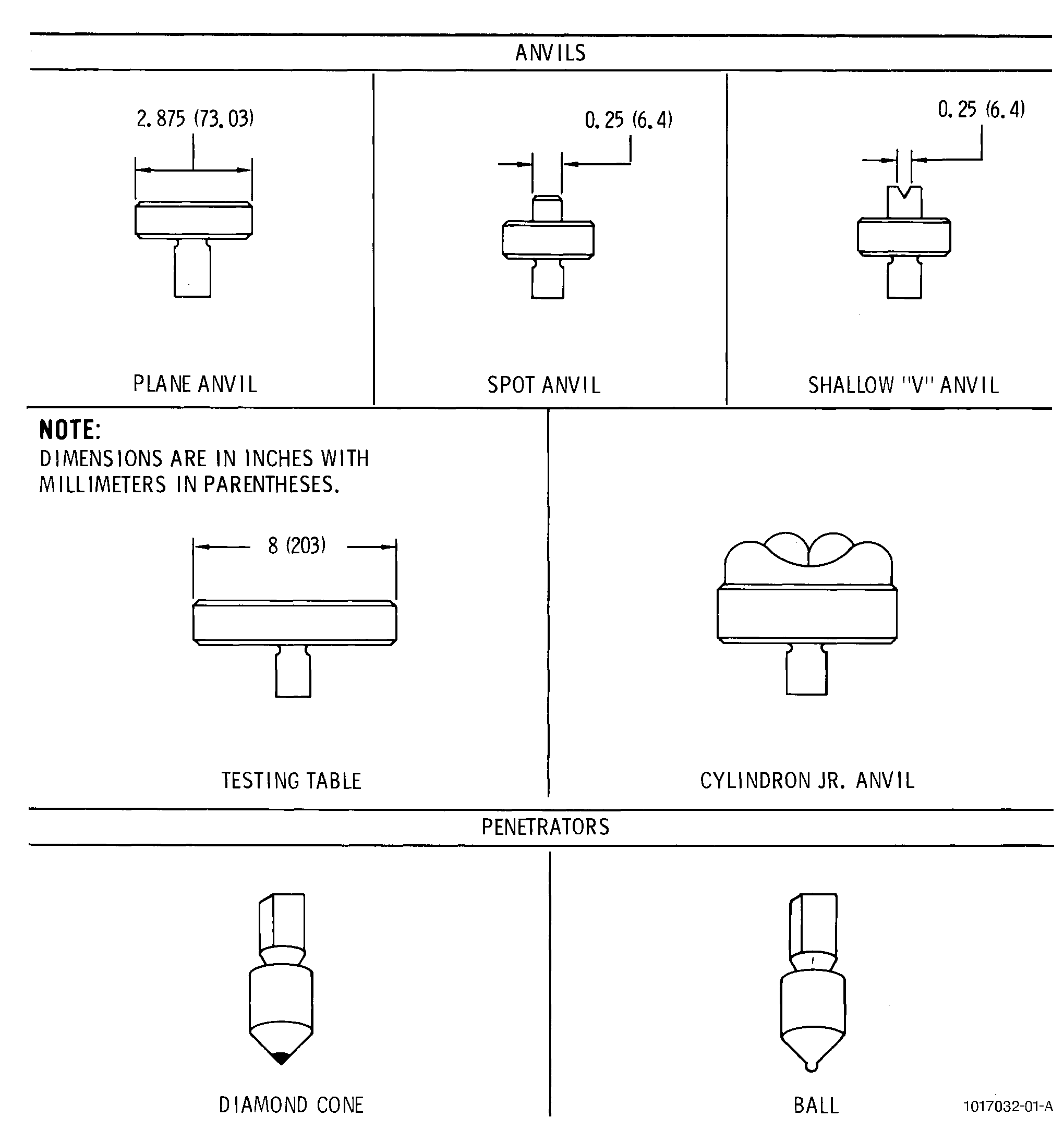
| B. | The machine supports the test specimen on an anvil. A variety of anvils are available as indicated in Figure 1. The proper anvil should be selected to completely support the test part while the surface to be tested is parallel to the anvil surface and perpendicular to the penetrator. |
| C. | There are 2 types of stationary Rockwell hardness testers: |
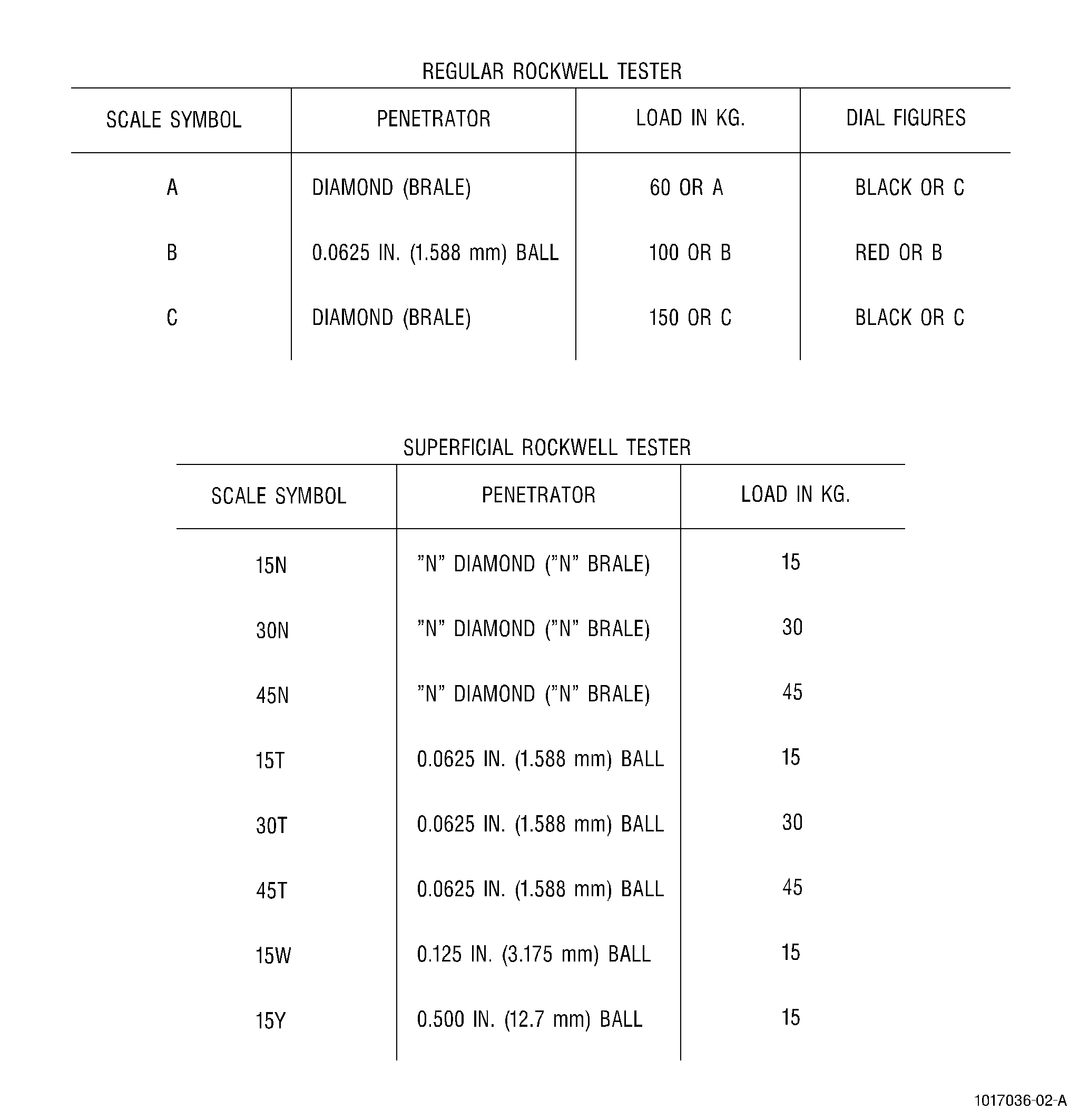
| (1) | The regular tester applies a minor load of 10 kilo-grams force (kgf) and a major load of 60, 100, or 150 kgf and uses either a diamond sphero-conical penetrator or steel balls of 1.588, 3.175, 6.350, or 12.70 mm diameter( Figure 2). |
| (2) | The superficial tester is a specialized form of the regular hardness tester. It operates by the same principle as the regular tester but uses a smaller minor load of 3 kgf and smaller major loads of 15, 30, and 45 kgf. This tester uses a steel ball penetrator 1.588, 3.175, or 12.7 mm in diameter or a diamond sphero-cone. This tester is used in testing thin strips or sheet material or under conditions where large test machines or loads are destructive or undesirable. See Figure 2. |
| NOTE: |
|
| D. | The scale and type of tester shall be specified in the Engine/Shop Manual. The scale shall define the penetrator and load. |
| 2 . | Equipment. |
| Subtask 70-34-03-220-091 |
| E. | Rockwell Hardness Tester (Regular). |
| NOTE: |
|
| F. | Rockwell Hardness Tester (Superficial). |
| NOTE: |
|
| G. | Penetrator (Regular). See Figure 1. |
| (1) | Diamond sphero-cone (regular configuration). |
| (2) | Steel ball. |
| (a) | 1.588 mm diameter. |
| (b) | 3.175 mm diameter. |
| (c) | 6.350 mm diameter. |
| (d) | 12.70 mm diameter. |
| H. | Penetrator (Superficial). |
| (1) | Steel ball 1.588, 3.175, 12.7 mm diameter. |
| (2) | Diamond sphero-cone (superficial configuration). |
| I. | Anvil. See Figure 1. |
| (1) | Plane anvil. |
| (2) | Spot anvil. |
| (3) | Shallow "V" anvil. |
| (4) | Testing table. |
| (5) | Cylindron Jr. anvil. |
| 3 . | Materials. |
| Subtask 70-34-03-220-092 |
| J. | Hardness blocks for varied scales and ranges. |
| 4 . | Procedure. |
| Subtask 70-34-03-220-093 |
| K. | Prepare and qualify the specimen for hardness testing: |
| (1) | Ensure that the surface of the part to be tested is perpendicular to the axis of the penetrator and parallel to the face of the anvil. |
| (2) | Make sure that the test surface and machine contact surfaces are clean and free from oxidation and from foreign matter. |
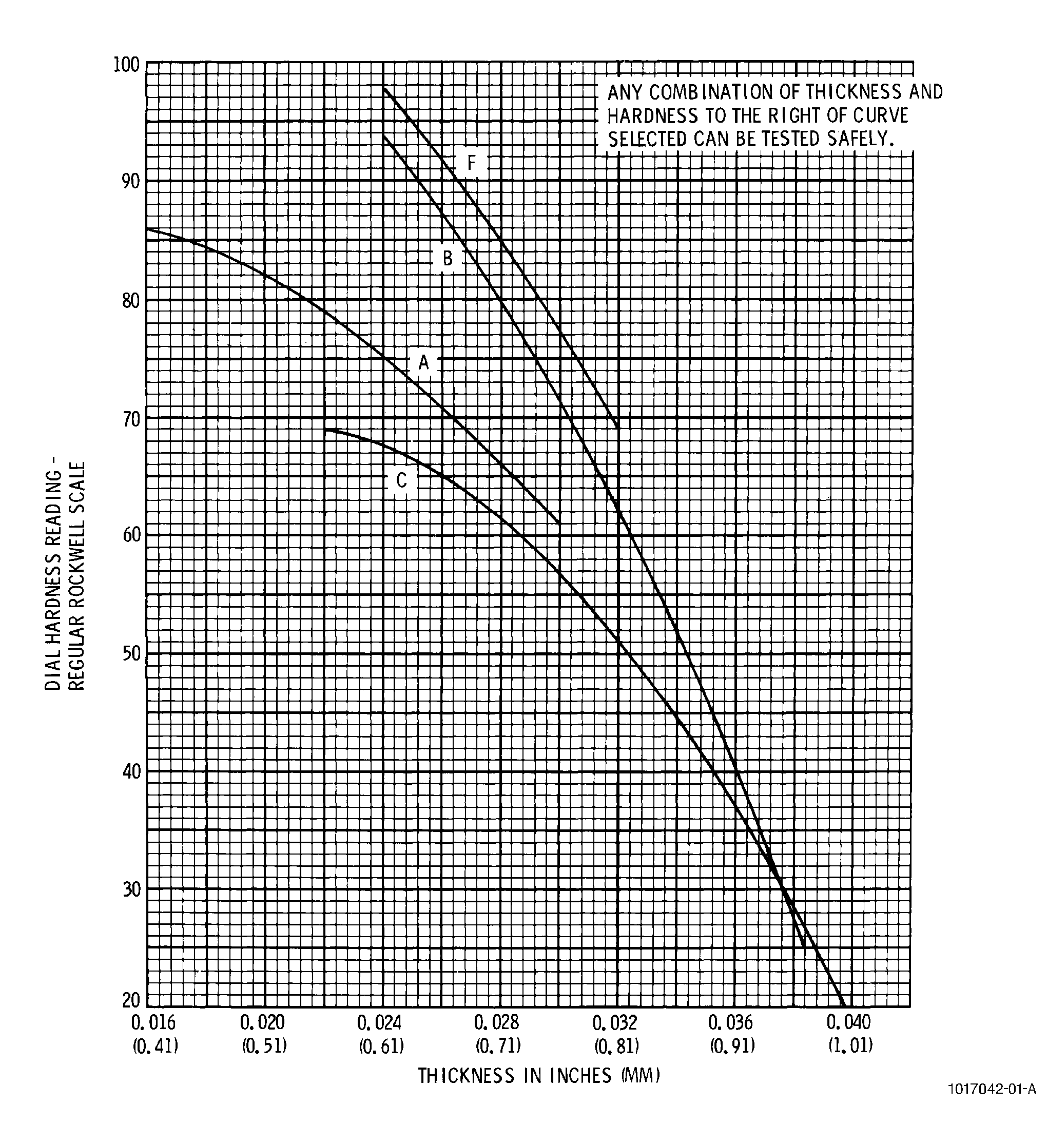
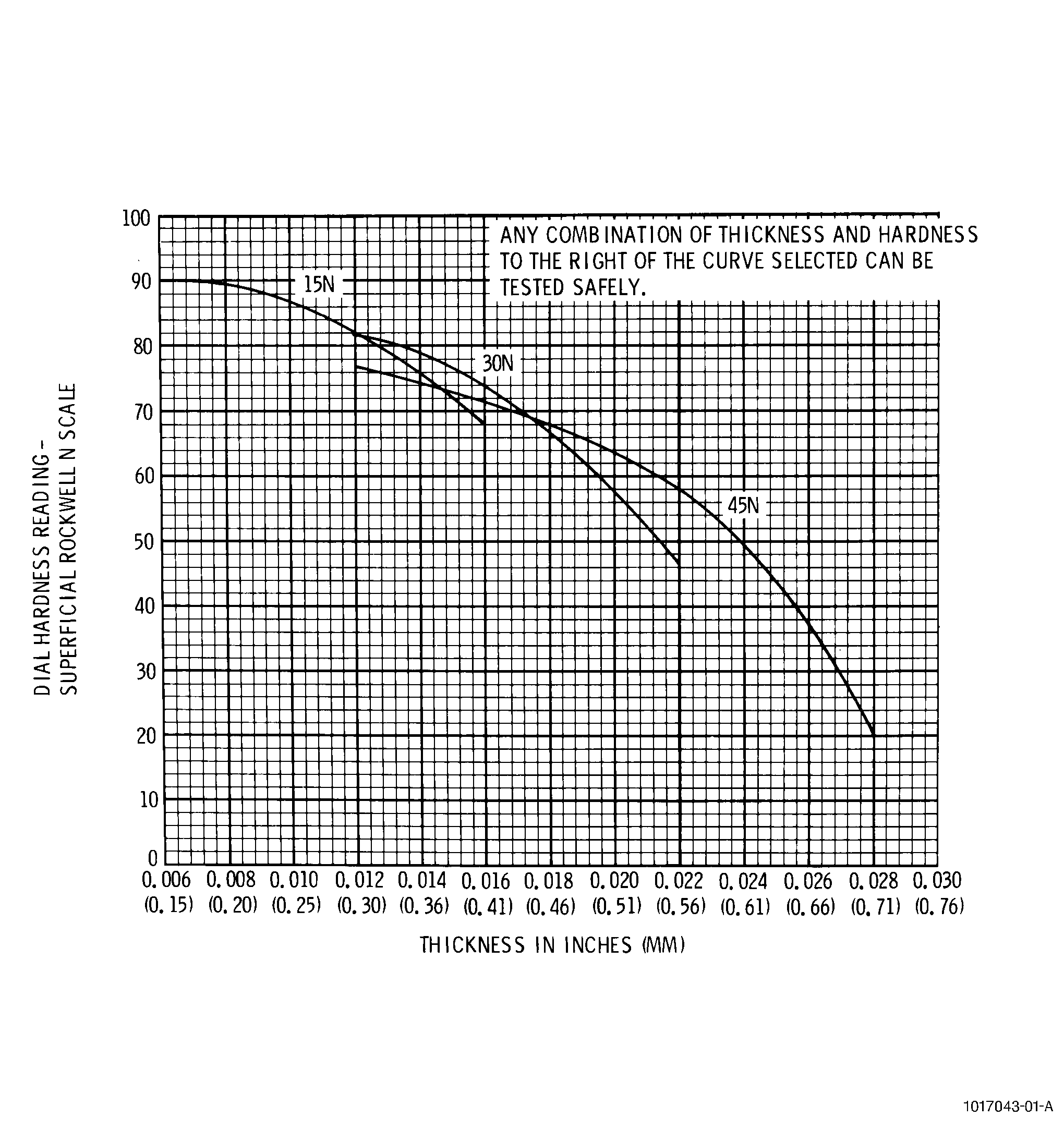
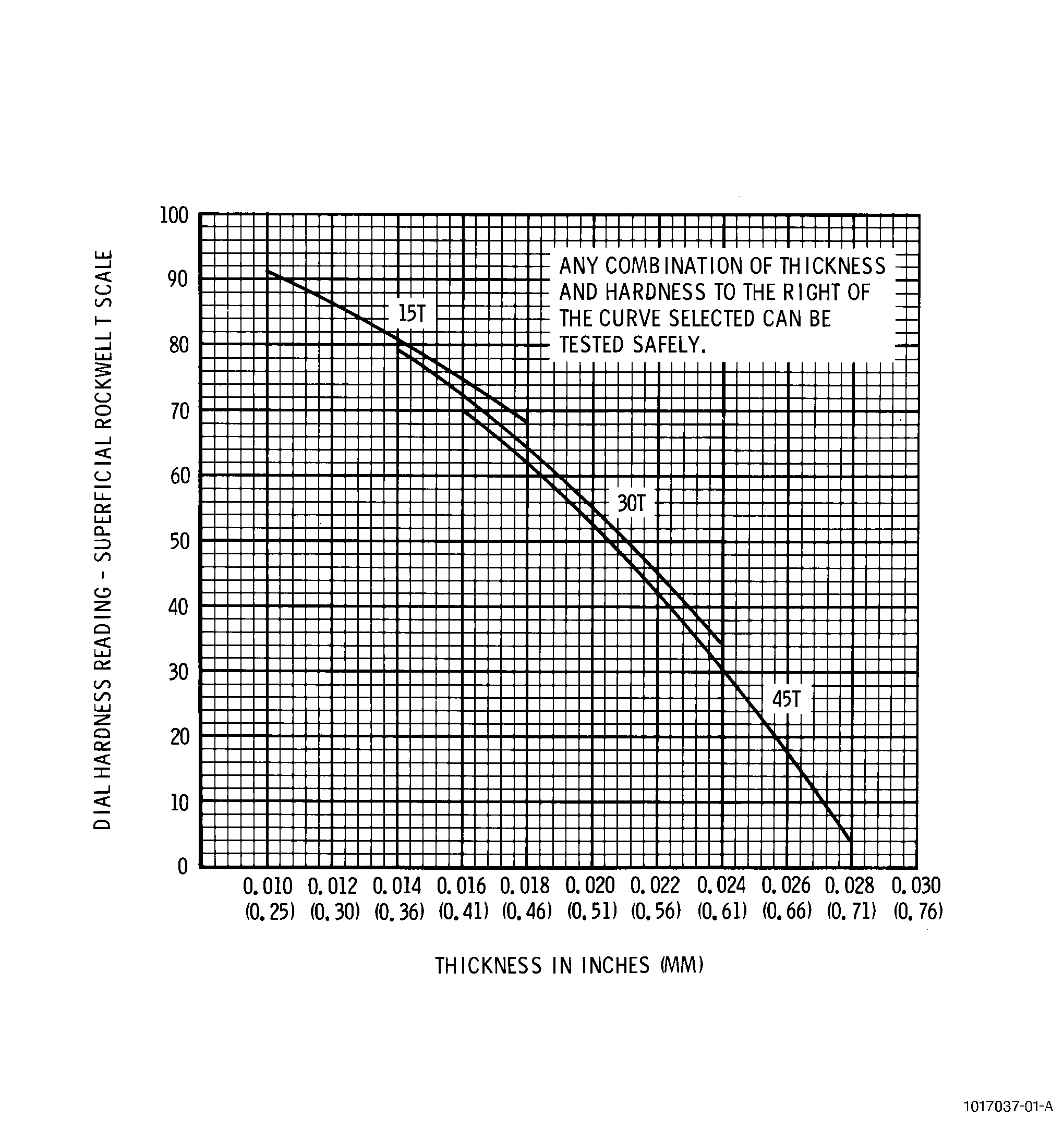
| (3) | Make sure that the part to be tested is thick enough to avoid having penetrator impression show on the anvil side of the part. Refer to Figure 3, Figure 4, and Figure 5. |
| (4) | For thermal spray coatings, preparation of the surface is critical for successful hardness testing. |
| (a) | The coating must be ground to a matte finish with the coating aspirates removed. |
| (b) | This can be accomplished using 120-320 grit metallurgical grinding papers using minimal pressure during removal. |
| (c) | Coating removal should be a minimum of 0.001 inch (0.0254 mm) for the superficial 15T and 15N scales and a minimum of 0.005 inch (0.127 mm) for the 15Y scale. |
| (d) | Care must be taken to provide even removal across the specimen. Flatness of the specimen should be 0.002-0.005 inches (0.05-0.127 mm). It is also important to prevent excessive coating removal, which would invalidate the test due to thickness concerns. |
| (e) | With all thermal spray coatings, the thickness vs. hardness value charts (Figure 3, Figure 4, and Figure 5) should be reviewed to insure that the specimen has been coated with sufficient material for a valid hardness reading. |
| L. | Establish general test conditions as specified in the process document and the following: |
| (1) | Position part so that the distance from the center of an impression to the edge of the part is at least 2-1/2 times the length of the impression and 3 times the diameter from another impression measured center-to-center. |
| (2) | If not indicated, select an anvil to completely support the weight and shape of the part being tested. |
| (3) | Inspect penetrator for defects and replace if necessary. |
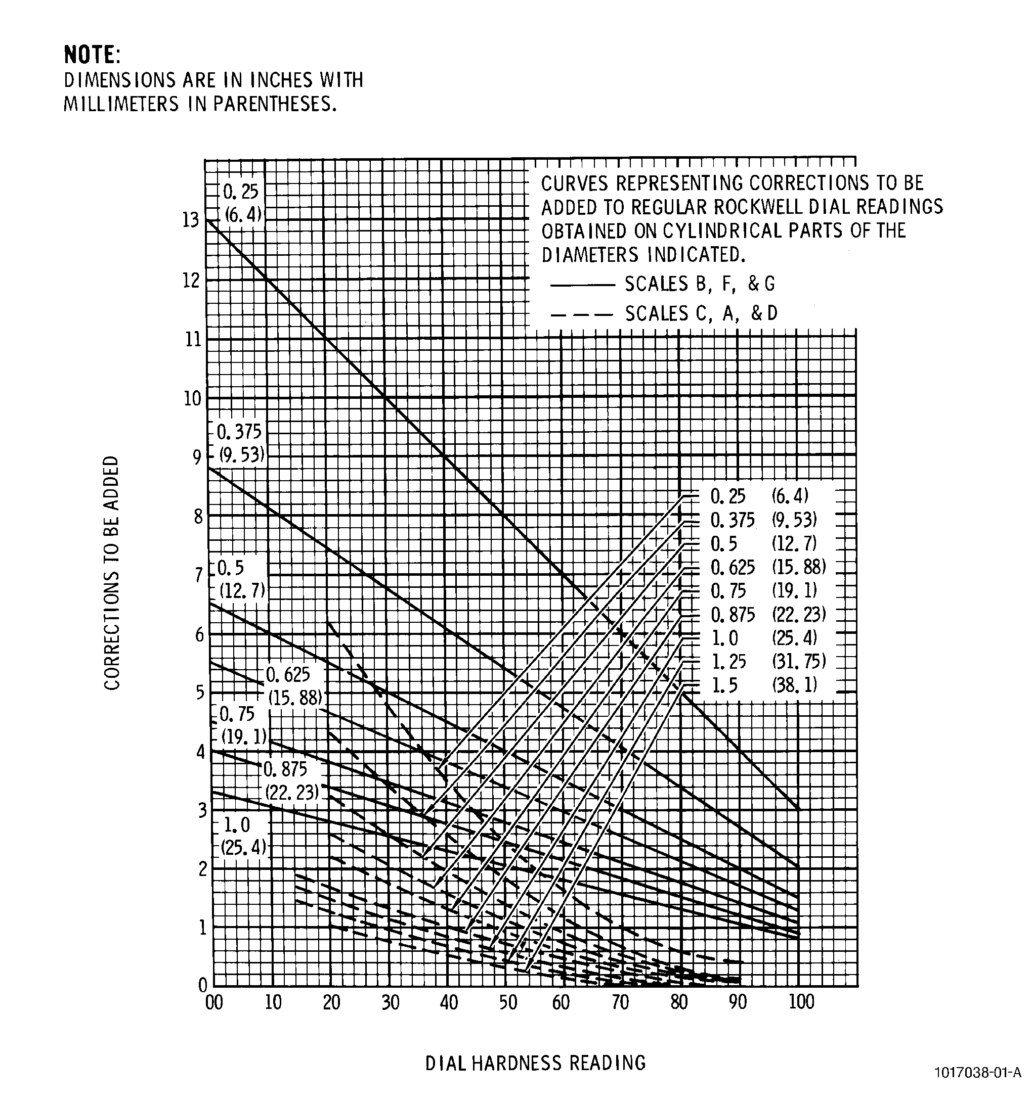
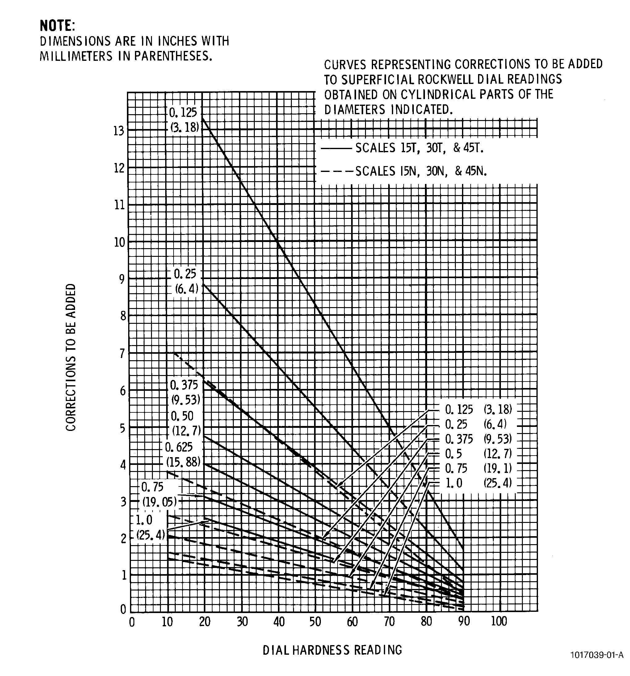
| (4) | If the surface to be tested is curved, the concave side of the curved surface should face the penetrator and Figure 6 and Figure 7 should be used for correction factors with the readings. |
| WARNING: |
|
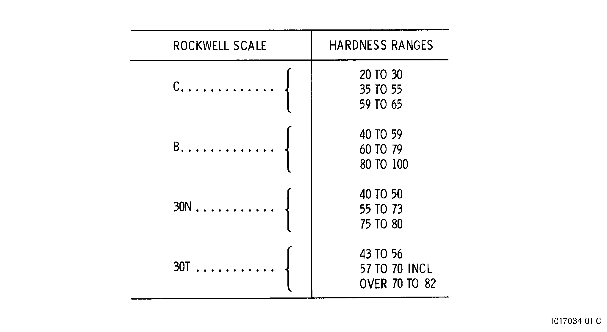
| M. | Perform test on blocks of known hardness that are in the same hardness range as the test part. Compare test results with actual hardness of test block to ensure accuracy of test equipment and measuring techniques. See Figure 8. |
| NOTE: |
|
| N. | Apply major load for 2 seconds, unless otherwise specified. |
| (1) | Do not use the first reading after changing machine setting, anvil, penetrator, or testing at a different hardness range. |
| (2) | Take a minimum of 3 hardness readings. |
| (3) | If the load setting pointer is moved past either the set point or the major load point for the test, the load should be released and the test performed at a different position. |
| (4) | Record the hardness value by indicating the scale used per the following example: |
| NOTE: |
|
|
|||||||||||||||||||||||||||||||||||||||||||||||||||||||||||||||||||||||||||||||||||||||||
| 5 . | Quality Assurance. |
| Subtask 70-34-03-220-094 |
| WARNING: |
|
| O. | If the tester is newly installed or rebuilt, calibrate the tester as follows: |
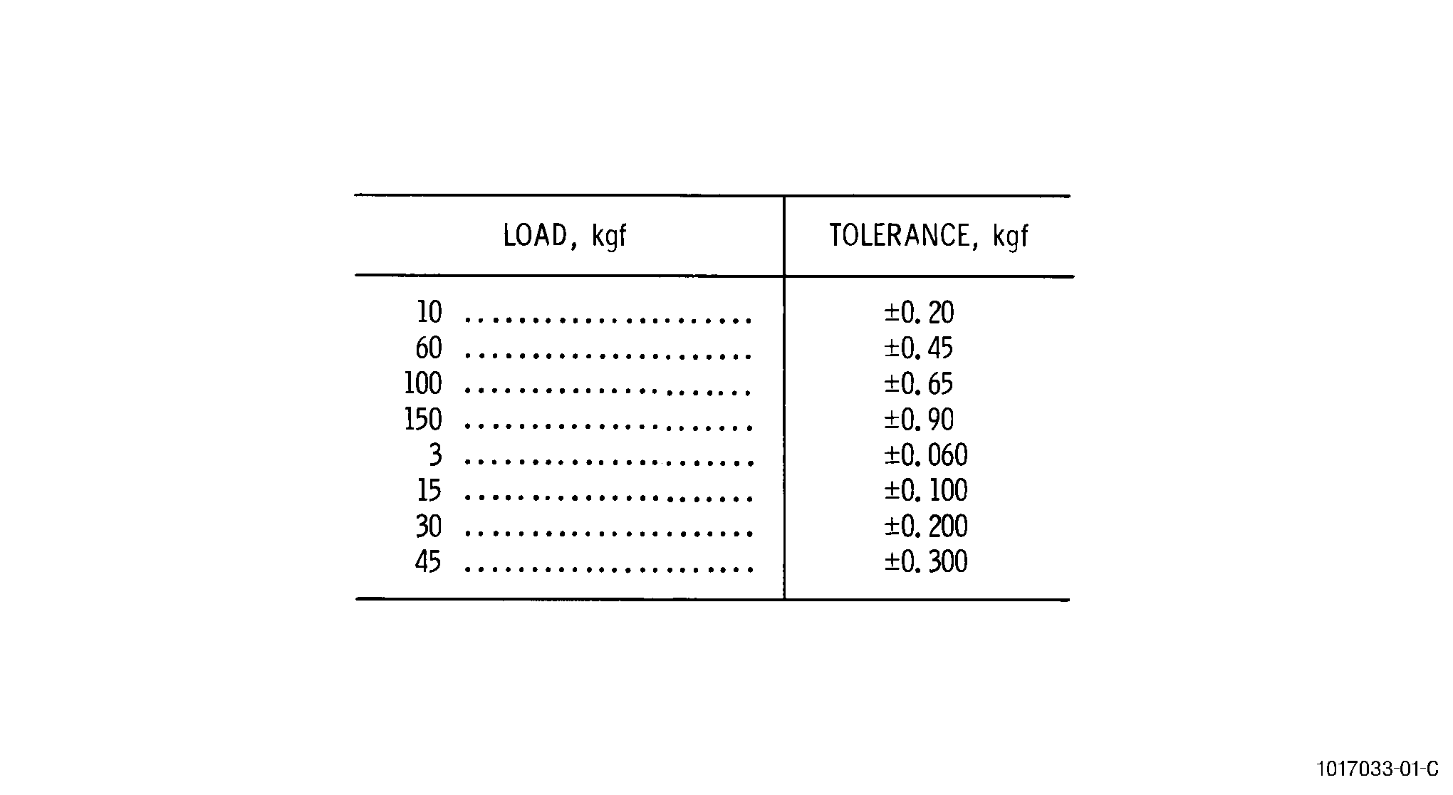
| (1) | Verify applied loads as follows: |
| (a) | Regular testing machines should be calibrated at loads of 60, 100, and 150 kgf. |
| (b) | Superficial testing machines should be calibrated at loads of 15, 30, and 45 kgf. |
| (c) | Check loads using standardized dead weights and proving levers or other approved methods. The tolerance under the major load must be within ±1 percent. |
| (d) | Verify machine at minor load before and after removal of the major load. |
| (e) | Apply load and take 3 readings at each of the 3 positions of the power lever using standard hardness test block. |
| (f) | Calculate mean for each group of 3 readings. The applied loads are calibrated if mean readings fall within tolerances of Figure 9. |
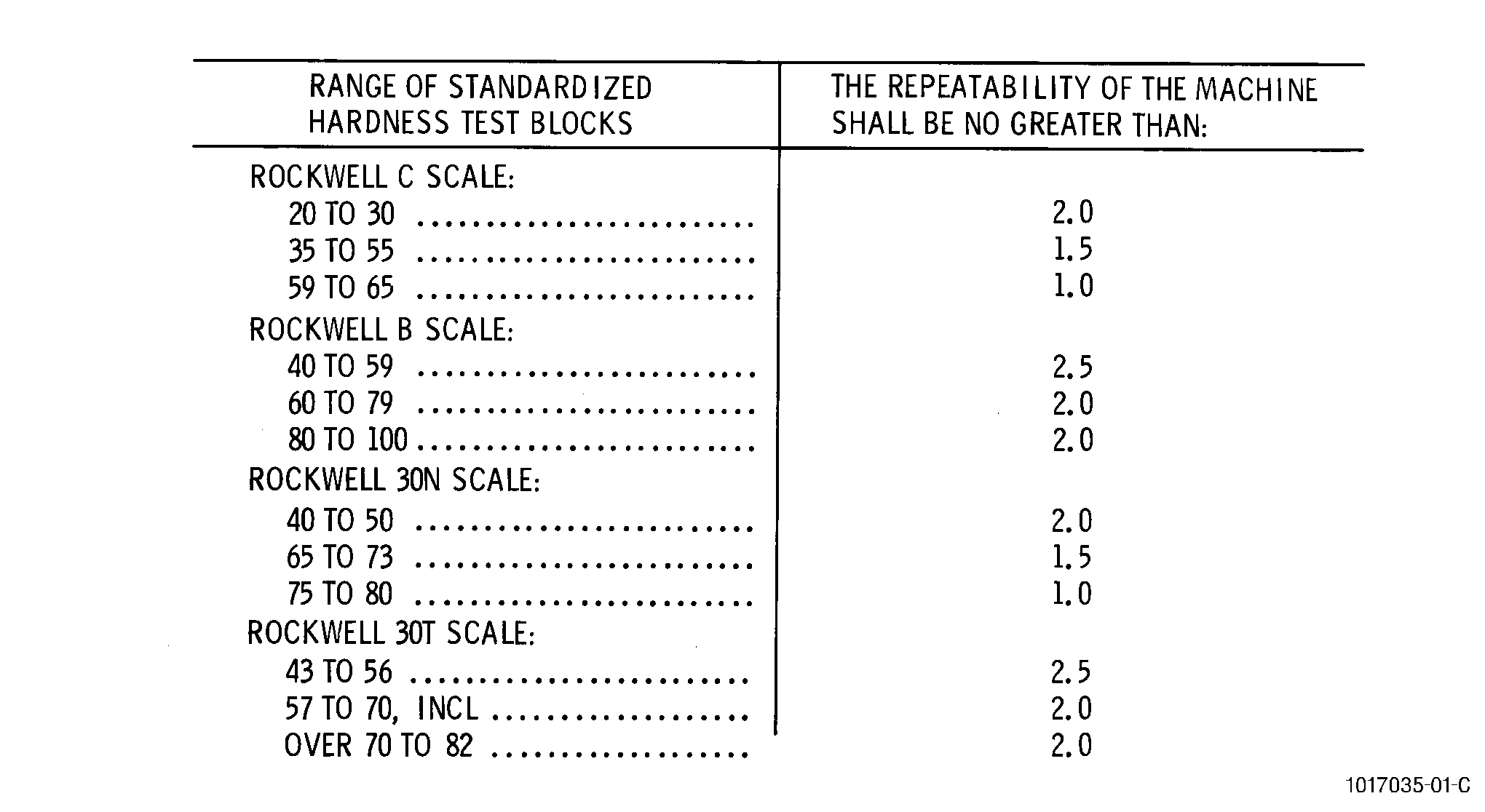
| (2) | Verify machine repeatability as follows: |
| (a) | Take 5 hardness readings on each of the 3 hardness test blocks of different hardness levels as indicated in Figure 8. |
| (b) | Calculate repeatability using R1, R2, and R5 as hardness readings in increasing order. R5 minus R1 equals the repeatability of the hardness readings. |
| (c) | If repeatability limits of Figure 9 are met, machine is verified. |