| COMMERCIAL ENGINE STANDARD PRACTICES MANUAL | Dated: 04/01/2015 | |
| SPM 70-41-01 TITANIUM WELDING PROCEDURE | ||
| COMMERCIAL ENGINE STANDARD PRACTICES MANUAL | Dated: 04/01/2015 | |
| SPM 70-41-01 TITANIUM WELDING PROCEDURE | ||
| TASK 70-41-01-310-002 |
| 1 . | General. |
| A. | Parts made of titanium and its alloys require special handling throughout the repair welding process. Titanium absorbs atmospheric gases and surface contamination at elevated temperatures which permanently affect its physical and mechanical properties. For this reason it is mandatory that an effective inert gas atmosphere shield the weld puddle and heated base material during the welding operation and that the material surface be free of oxides, oil, dirt and other impurities of contamination. Once cleaned, the part should not be handled except with clean cotton gloves since even fingerprints may contaminate the weld sufficiently to cause weld or base metal defects. |
| WARNING: |
|
| B. | Cleaning and acid pickling procedures as described in TASK 70-22-02-110-014, Special Cleaning Procedure No. 2 - Titanium Cleaning, are normally used before and after welding and heat treating. However, an alternate cleaning procedure may be used which consists of steam cleaning the weld repair area or part per TASK 70-21-03-160-001, Cleaning Method No. 3 - Steam Cleaning, (or alkaline cleaning in accordance with paragraph 5.B. in 70-22-02), and scrubbing the repair area with methyl-ethyl-ketone C04-001 or acetone C04-003 . The weld repair area is considered to be the total area affected by high welding heat, including the back side of the material. The back side of the weld area must be steam cleaned, abrasive polished and solvent wiped as described below. If the surfaces are inaccessible for such cleaning, chemical cleaning of the entire case per TASK 70-22-02-110-014, Special Cleaning Procedure No. 2 - Titanium Cleaning, using minimum allowable times in each chemical is required. |
| C. | The repair area is then prepared for welding by polishing with 150-320 grit silicon carbide abrasive and prepped with a high speed rotary file for defect removal. The polished area should extend 0.500 inch (12.70 mm) beyond the weld zone on both top or bottom surfaces as described above. |
| D. | After abrasive polishing, the use of a clean stainless steel wire brush is allowed to assure a clean smooth surface is obtained prior to weld repair. |
| WARNING: |
|
| E. | Upon completion of mechanical cleaning, the areas to be welded should be given a final solvent wipe using methyl-ethyl-ketone or acetone and a clean lint-free cotton cloth. |
| 2 . | Crack Preparation. |
| Subtask 70-41-01-310-021 |
| A. | Cracks should be prepared in general accordance with TASK 70-41-00-310-001, Welding and Brazing Practices; however, if grinding wheels have been used, the cut should be dressed with a high-speed steel or carbide rotary file to remove all traces of embedded abrasive before proceeding to the etching operation. |
| B. | Etch, using etchant described in item 6 of table 1 in paragraph 3.G. TASK 70-41-00-310-001, Welding and Brazing Practices, then rinse with potable or low mineral tap water. |
| WARNING: |
|
| C. | Dry by blowing with clean shop air, or by wiping with a clean, lint-free cotton cloth moistened with acetone or methyl-ethyl-ketone. |
| 3 . | Procedure. |
| Subtask 70-41-01-310-022 |
| WARNING: |
|
| A. | Welding of parts should be initiated within 12 hours after cleaning. If more than 48 hours have elapsed since cleaning of parts or more than 8 days since cleaning of filler wire or weld test strips, reclean in accordance with paragraph 1.C. to 1.E. of this procedure. |
| WARNING: |
|
| (1) | Wipe all areas to be welded with acetone or methyl-ethyl-ketone and a clean lint-free cotton cloth. |
| (2) | When practical, place parts in a welding chamber and begin gas purging with welding grade argon or helium. (Argon is preferred.) |
| (3) | Test for adequacy of gas purging by welding test strips of titanium alloy. These strips shall be welded each time a chamber is loaded and when purging is interrupted. |
| (a) | Make bead-on-plate welds with or without filler wire on titanium alloy strips. The weld beads shall be at least 2 inches (51 mm) long and depth of the melt shall be at least as deep as the depth of the area being repaired. |
| (b) | If the test strips show no color on the weld bead other than bright silver or light straw, the purge can be considered adequate. If other colors are present, continue or repeat purging procedure until test strips indicate that it is adequate. |
| NOTE: |
|
| (4) | The use of filler wire is recommended for most repairs. Unless otherwise specified in the process document, use TASK 70-41-00-310-001, Welding and Brazing Practices, to determine the proper filler wire to be used. |
| (5) | Repair weld the part only after adequate purging has been verified. |
| NOTE: |
|
| 4 . | Local Inert Gas Shielding. |
| Subtask 70-41-01-310-023 |
| A. | In some instances, due to the size of the part, repair area access, or part geometry, use of a controlled atmosphere welding chamber may not be desired. Under this circumstance, the use of oversized torch gas cups, trailing shield, backup shields, and preplaced auxiliary shielding devices are permitted provided appropriate judgment and caution are exercised. The welding requirement and objective is to provide thorough and uninterrupted inert gas shielding of the heated area with a welding grade of argon. When this is accomplished, out-of-chamber welds can be produced with excellent results. |
| (1) | Welding inert gas cups and shielding devices should be designed and selected to provide required gas coverage for repair welding each application. The method chosen should be set up to duplicate the actual part condition and evaluated initially for adequateness of shielding gas by producing welds on scrap or sample titanium pieces. The welding procedure used should include provisions for adequately shielding any area at or adjacent to the repair that is exposed to welding heat. Typical types of gas backup cups are illustrated in TASK 70-41-00-310-001, Welding and Brazing Practices. Gas cups of similar configuration can be used as trail cups behind the weld torch to provide additional shielding gas at the top side of the joint. |
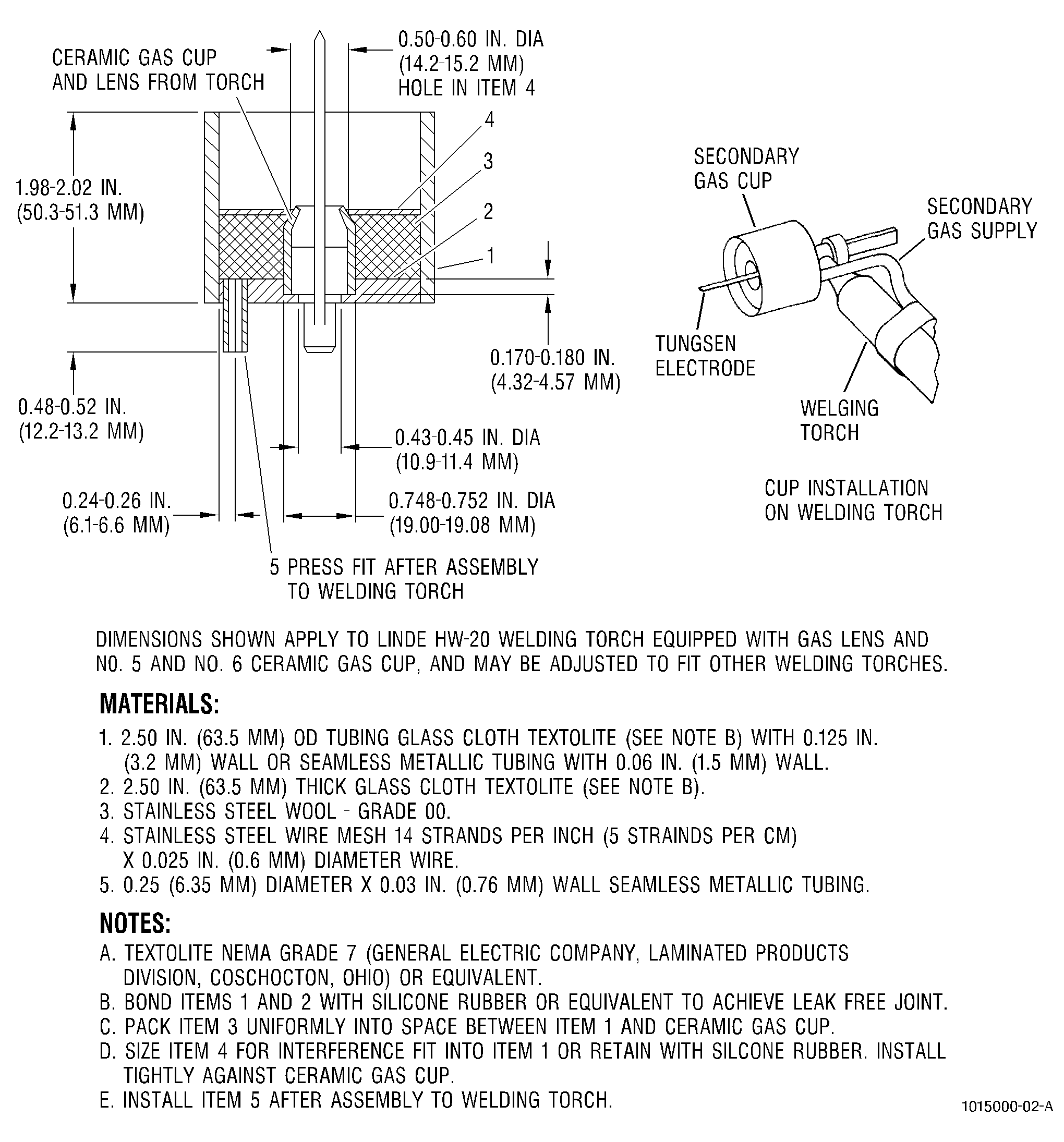
| (2) | To improve weld torch gas shielding capability, an auxiliary torch cup may be used which encompasses the standard torch weld cup as illustrated in Figure 1. |
| 5 . | Post Welding Preparation. |
| Subtask 70-41-01-310-024 |
| A. | When welding has been completed, steam clean the part per TASK 70-21-03-160-001, Cleaning Method No. 3 - Steam Cleaning, in preparation for heat treatment. |
| B. | Stress-relieve weld repaired parts as directed in the repair section for the specific part. |
| C. | Inspect in accordance with the fluorescent-penetrant method, as referenced for the specific part in the appropriate Engine/Shop Manual. |