| COMMERCIAL ENGINE STANDARD PRACTICES MANUAL | Dated: 04/01/2008 | |
| SPM 70-41-02 BRAZING OF JOINTS IN FORMED TUBING | ||
| COMMERCIAL ENGINE STANDARD PRACTICES MANUAL | Dated: 04/01/2008 | |
| SPM 70-41-02 BRAZING OF JOINTS IN FORMED TUBING | ||
| TASK 70-41-02-310-003 |
| 1 . | General. |
| A. | Joints in stainless steel tubing can be torch brazed when repair is authorized by Engine/Shop Manual. Torch brazing of tube joints shall be performed only by personnel qualified by training and experience in the practice of torch brazing. |
| B. | Joints in nickel based alloy tubing (Inconel) cannot be repaired by torch brazing. Repair of this type of tubing must be accomplished by section replacement. The high temperatures required for re-melt and braze filler material flow make torch brazing impractical for nickel-based alloy tubing. |
| 2 . | Preparation of Joint. |
| Subtask 70-41-02-310-031 |
| A. | If any part of the joint to be brazed has been used before, all residual filler metal must be removed from it before attempting to braze the joint. The residual metal could prevent proper assembly because of interference. Braze removal can be accomplished by 2 methods: chemical and abrasive. |
| (1) | Chemical Removal. |
| Braze filler metal can be removed from part small enough to be immersed in an acid bath. This method can also be used by swabbing the acid solution onto large or unwieldy parts that cannot be immersed. Proceed as follows: |
| (a) | Protect workbench, tools, etc. with a plastic dropcloth before mixing or using the acid. |
| WARNING: |
|
| WARNING: |
|
| (b) | Prepare a 50 volume percent solution of C04-072 nitric acid by slowly pouring one part of nitric acid (67 to 70 wt %) into one part of water while stirring vigorously. |
| (c) | Immerse the part in solution until residual braze filler metal is dissolved. If immersion is impractical, swab with a plastic cloth or swab affixed to a stainless steel or plastic rod.(Cotton swabs are acceptable for small areas.) |
| (d) | Rinse part thoroughly with water to remove all acid residue. |
| CAUTION: |
|
| (2) | Abrasive Removal. |
| Areas of high residual braze filler metal, such as original braze fillets, can be removed carefully with a silicon carbide sandroll or abrasive. Do not use aluminum oxide. After high metal is removed, the remaining filler metal can be removed manually, using 80 grit abrasive paper or cloth or chemicals, as described in paragraph2.A.(1), above. |
| B. | Gap Clearance. |
| Trial fit the parts to be joined, and check to be sure that the clearance between faying surfaces does not exceed 0.005 inch(0.13 mm). On round tube joints, the diametral clearance should be 0.002-0.005 inch (0.05-0.13 mm). Too much clearance will prevent the filler metal from bridging the gap, even if both faying surfaces are wetted. If necessary, rework tube ends, couplings or fittings to obtain proper clearance. |
| C. | Surface Cleaning. |
| It is necessary to clean the surfaces of the joint immediately before brazing to ensure that filler metal will wet the faying surfaces. Flux will not remove oil or grease films, or surface oxides. Further, it is necessary to polish the surface to produce the capillary action required to cause the filler metal to flow into the joint. Clean and polish as follows: |
| (1) | Insert plugs in ends of tubing to prevent entry of abrasive dust. |
| (2) | Polish approximately 1.50 inches (38.1 mm) of each tube end with 180 grit abrasive paper or cloth. Use circumferential polishing strokes, rather than axial or longitudinal, to facilitate the flow of filler metal. |
| WARNING: |
|
| (3) | Remove abrasive dust completely from part by wiping the polished areas with a clean cloth wetted with acetone or methyl-ethyl-ketone. |
| (4) | Remove plugs, being careful to avoid touching the cleaned areas with bare hands. |
| 3 . | Brazing. |
| Subtask 70-41-02-310-032 |
| WARNING: |
|
| A. | Mark the insertion depth of the tube, as specified in the appropriate assembly or repair section, by marking a light scribe mark. Braze as follows: |
| WARNING: |
|
| CAUTION: |
|
| (1) | Clean rings of filler metal in acetone C04-003 or methyl-ethyl-ketone C04-001 , and install in internal grooves in coupling. Surface oxides on braze filler may be removed mechanically using dry No. 00 grade steel wool. Apply a thin coating of flux to the entire inner surface of the coupling. If the joint is a simple lap joint in which the outer surface of one tube mates with the inner surface of another, lightly coat the entire inner mating surface of the female member with flux. |
| (2) | Coat the cleaned external surface of the male tube member with flux, and insert it in the coupling or mating tube. Make sure that insertion depth, as previously marked on tubes, is correct. |
| (3) | Braze Parameters. |
| (a) | Process - Oxy Acetylene. |
| (b) | Acetylene - 5 psi (34.5 kPa). |
| NOTE: |
|
| (c) | Oxygen - 12 psi (82.7 kPa). |
| (d) | Tip sizes - No. 1 to No. 4 (dependent on stock thickness). |
| (e) | Flame - neutral to slightly reducing. |
| (f) | Filler - AMS 4770 (low temp) or AMS 4772 (high temp). |
| (g) | Flux - AMS 3410 or AMS 3411 for AMS 4770 silver braze alloy. |
| (h) | Flux - AMS 3411 for AMS 4772 silver braze alloy. |
| CAUTION: |
|
| (4) | Move the flame around the joint to distribute the heat evenly; stainless steel does not conduct heat readily, and all parts of the joint must be heated directly by the flame. If a coupling with internal rings of filler metal is used, watch for the filler metal to flow to the outer edges of the coupling. In a simple lap joint, force feed the filler metal until flow into the joint is observed and can be seen around the entire periphery of the exposed edge of the joint. Do not pile up excessive filler metal at the exposed edge. |
| CAUTION: |
|
| (5) | Let the joint cool, then remove flux residue with a cloth saturated in warm water and a stainless steel wire brush. Flush the inside with hot water at minimum 150°F (66°C), or steam clean by blowing steam through the tube for 10 minutes minimum. Blow out residual water with filtered shop air. Where feasible, brazed tubes may be placed in boiling water for 10 minutes minimum to dissolve braze flux and blow dry with filtered shop air. |
| 4 . | Braze Acceptability Limits for Tubing. |
| Subtask 70-41-02-310-033 |
| A. | Inspect finished joints as follows: |
| (1) | Acceptability Limits for Brazing. |
| Visual indications are surface discontinuities which can be observed without magnification or aid of a non-destructive test process, that may indicate the presence of surface flaws. |
| (a) | The following acceptability limits apply to the braze filler material and are not applicable to the parent material. If type of imperfection is not assigned specific limits, the imperfection is not permitted. |
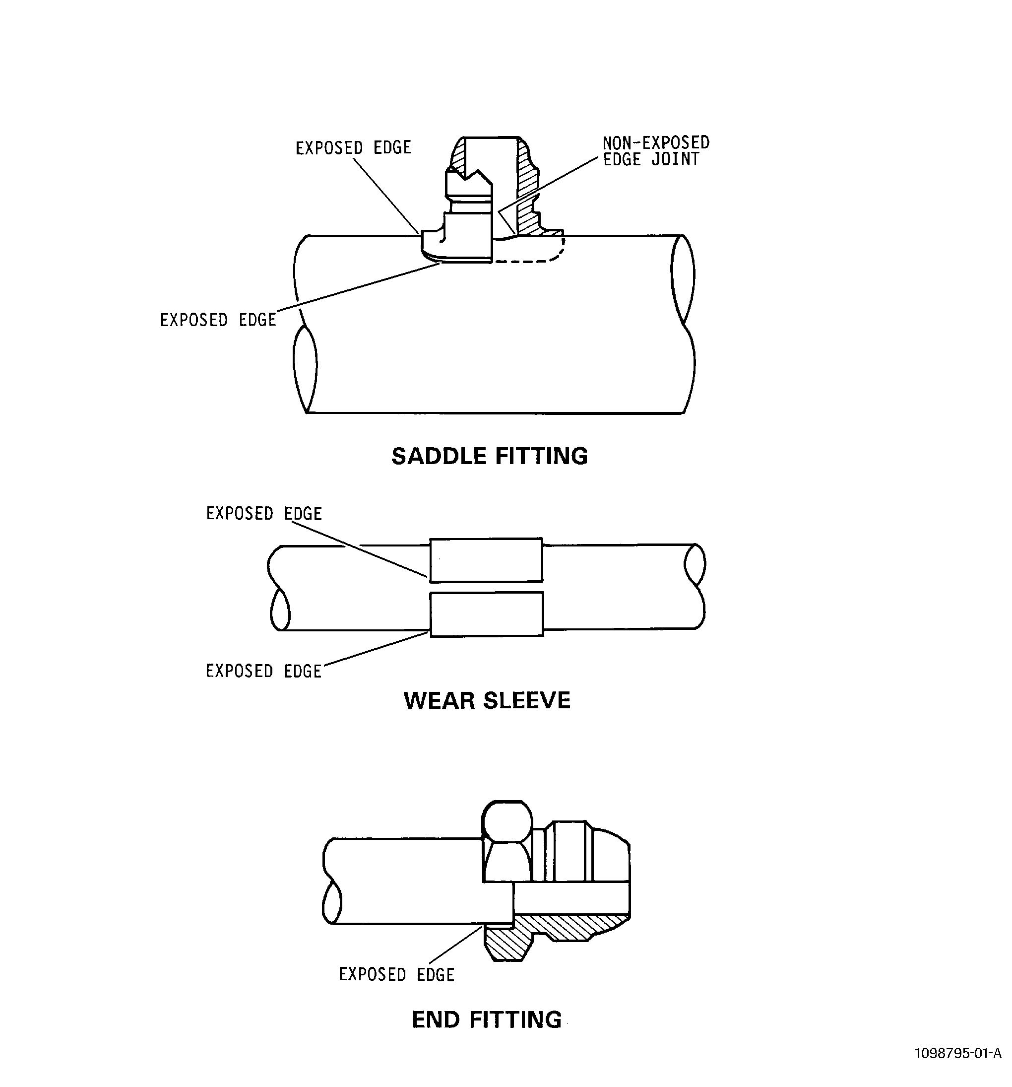
| (b) | Exposed Edge Joints. |
| The following imperfections in exposed edge joints as determined by visual inspection are permitted for all tubing braze joints when silver or gold braze filler material is specified. An exposed edge joint is defined as the external edge of the joint visible from the outside of the tube (See Figure 8). |
| 1 | Maximum Linear Fillet Length. (See Figure 7). |
| a | For material thicknesses less than or equal to 0.2 inch (5.08 mm): |
| DIM A maximum = material thickness. |
| DIM B maximum = 125 percent of material thickness or 0.10 inch (2.54 mm), whichever is greater. |
| b | For material thicknesses greater than 0.2 inch (5.08 mm): |
| DIM A maximum = 0.25 inch (6.35 mm) or material thickness, whichever is less. |
| DIM B maximum = 125 percent of DIM A. |
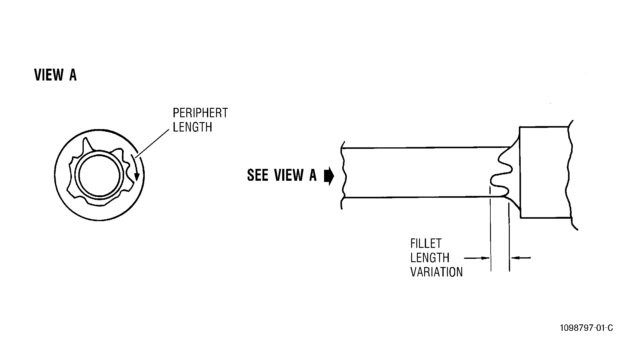
| 2 | Irregular Fillets. |
| a | Irregular fillets (Type A) are defined as non-linear fillet edges where the external braze fillet varies as shown in Figure 6. The fillet length (leg length) may not vary more than fifty percent of the maximum allowed fillet length [Ref para 4.A.(1)(b)1] within 0.25 inch (6.35 mm) of the periphery length for irregular fillet “Type A”. |
| b | Irregular fillets "Type B" are defined as non-linear surfaces of exposed filler material (See Figure 5). A maximum of 0.020 inch (5.08 mm) non-linearity above or below braze material surface is allowed for "Type B" irregular fillets. |
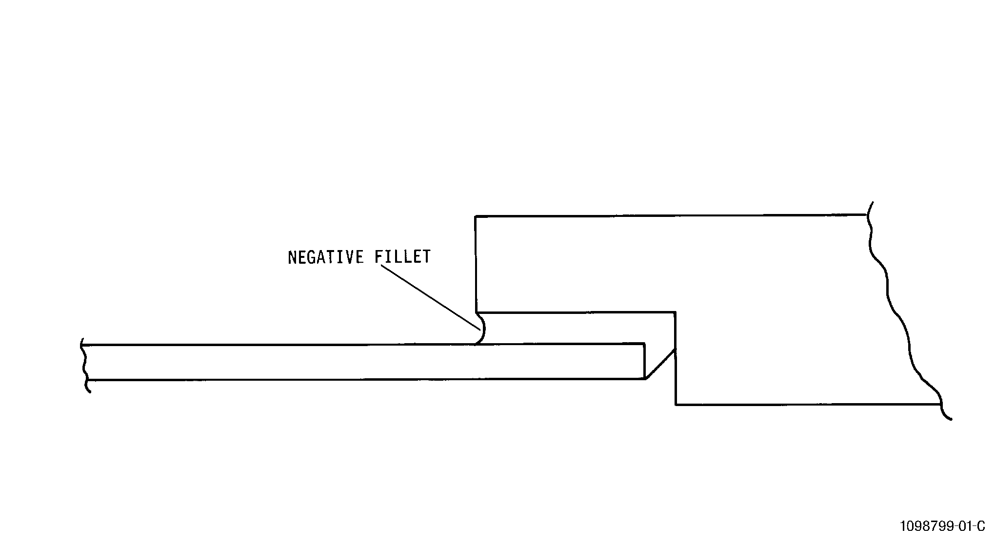
| 3 | Negative Fillet. |
| A Negative fillet is defined as a lack of filler material at the edge of the materials being joined by brazing (See Figure 4.) Localized concavity is when negative fillet length is not completely around the braze joint. Negative fillets or localized concavity are not allowed. |
| 4 | Pin Holes or Surface Porosity in Braze Fillets. |
| Pin holes or surface porosity is defined as gas pockets or small holes in the surface of the braze material that has a depth which may extend totally through the filler material. |
| 5 | Acceptability Limits for Pin holes or Porosity. |
| Pin holes with a maximum diameter of 0.030 inch (0.76 mm) are allowed with a minimum spacing of no greater than 2X the largest adjacent indication with a maximum of six pin holes allowed per linear inch(25.4 mm) of fillet. |
| (2) | Non-Exposed and/or Internal Edge Joints. |
| Imperfection limits do not apply for internal edge joints. Non-exposed and/or internal edge joints do not require inspection. |
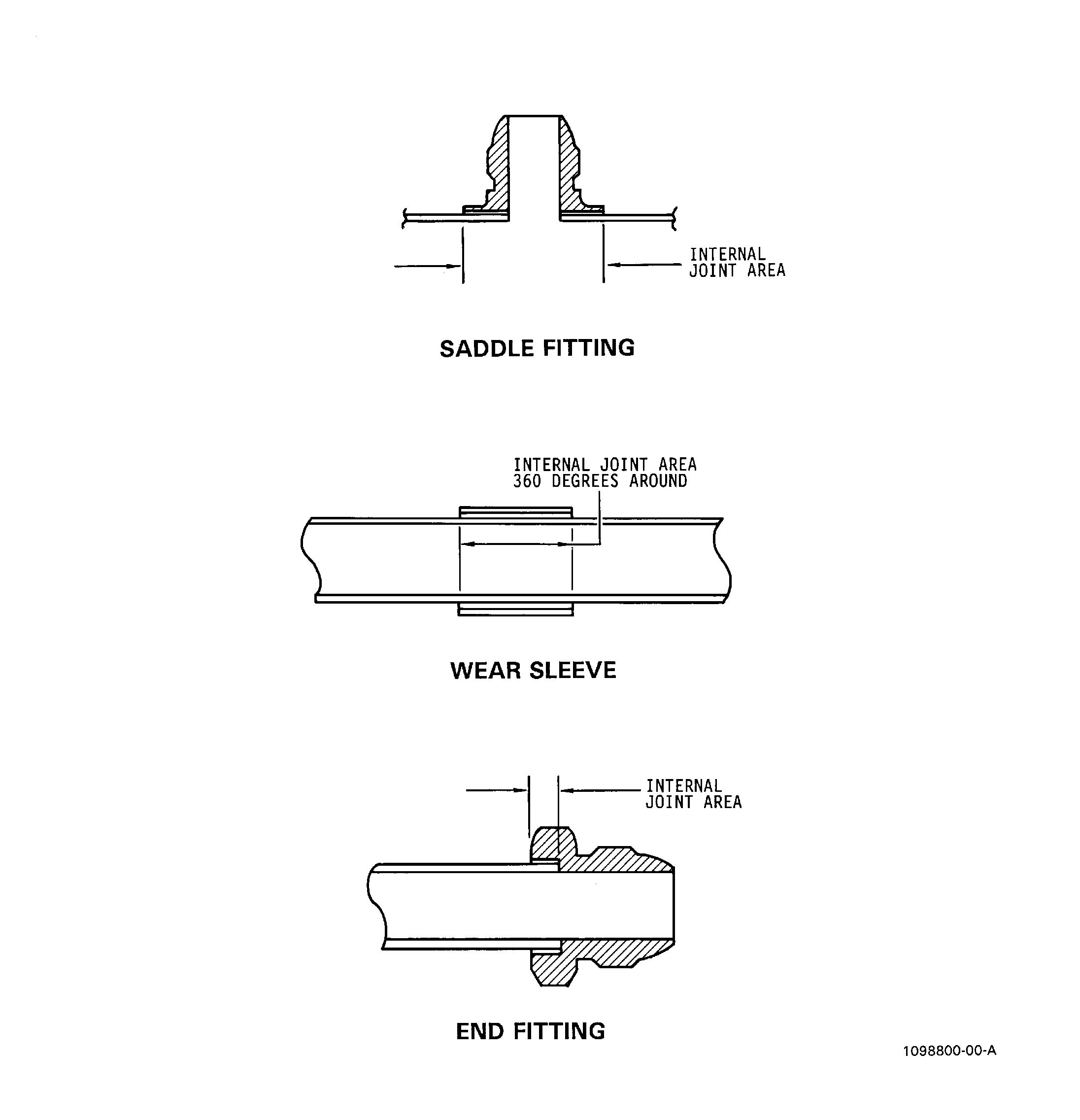
| (3) | Internal Joints Acceptability Limits. |
| An internal joint is defined as the common mating surfaces of the pieces being joined by braze filler material (See Figure 3). |
| (a) | Aggregate Area. |
| The total area of voids and unbonded areas compared to the total joint area shall not be greater than 35 percent for stainless steel tubing that utilize silver and gold alloys as braze filler material. The total area of voids and unbonded areas compared to the total joint area shall not be greater than 20 percent for nickel based alloy tubing that utilize nickel alloys as braze filler material. |
| NOTE: |
|
| (b) | Maximum Length of a Single Imperfection. |
| The maximum length of a single imperfection compared to the total length (measured in the same direction) of the joint shall not be greater than 35 percent. |
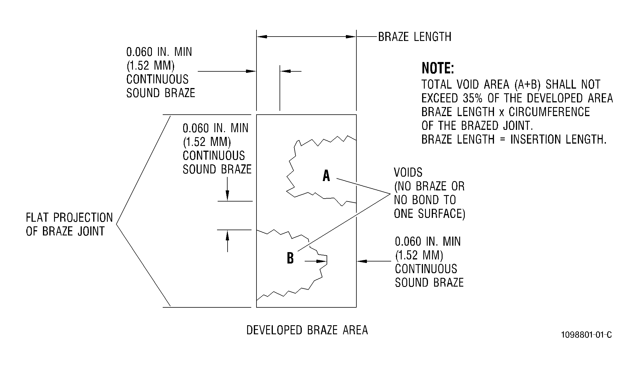
| (c) | Tubing Joints with Pressure Differential. |
| When the braze joint is exposed to the tube internal pressure and if a pressure check requirement exists, then a continuous sound braze is required for a minimum of 0.060 inch (1.52 mm) in any direction. This requirement takes precedence over the four requirements of paragraph 4.A.(1)(b). The 0.060 inch continuous sound braze may be located any where within the required internal braze area (see Figure 2). |
| (d) | Non-Pressure Differential Joints. |
| For non-pressure differential joints such as attachments for clamps, wear sleeves and brackets on formed tubing without a pressure differential between the internal and external environment of the joint, requirement for internal joint imperfections need only apply to an area of 0.150 inch (3.81 mm) width around the periphery. |
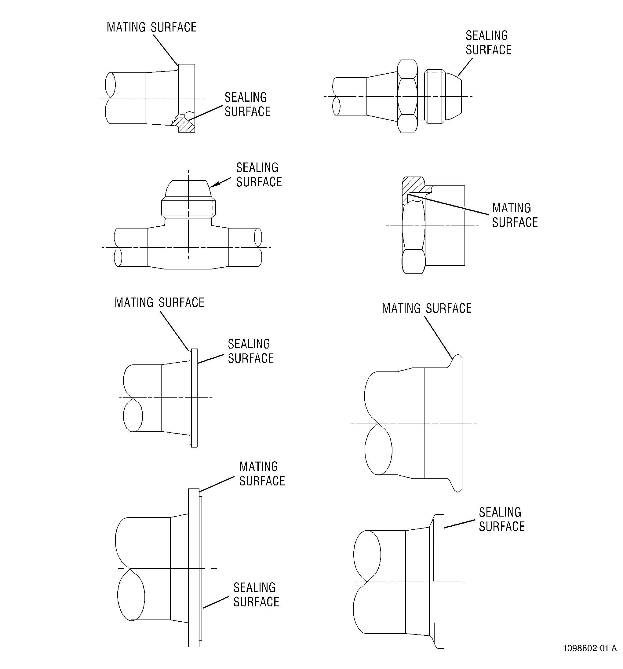
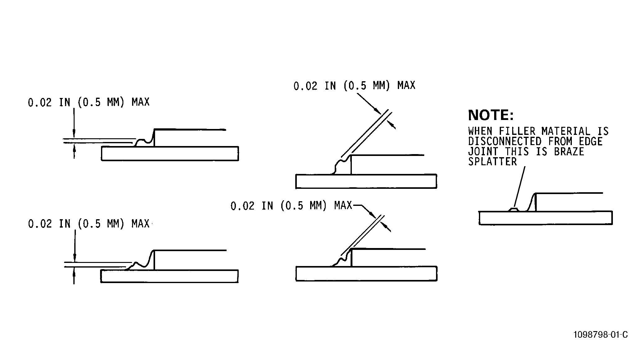
| (e) | Braze splatter/positive metal flashing and/or droplets of the braze alloy not part of the braze fillet and not exceeding 0.020 inch (0.51 mm) in height above the tube wall and/or fitting surface is acceptable up to 0.50 inch (12.7 mm) away from the braze joint. Braze splatter within 0.50 inch (12.7 mm) of the braze joint that exceeds 0.020 inch (0.51 mm) in height shall be removed to a height of 0.00 - 0.002 inch (0.0 - 0.51 mm) per Subtask 70-41-02-310-031, Preparation of Joint. Remove the splatter to produce a surface finish no greater than 32 microinches (0.85 micrometers) RMS. Visual comparison is an acceptable method for determining height of braze splatter. |
| Braze splatter not exceeding 0.003 inch (0.8 mm) in height above the wall and/or fitting surface is acceptable if located 0.050 inch (12.7 mm) away from the braze joint. Braze splatter greater than 0.50 inch (12.7 mm) away from the braze joint must be removed to a height of 0.00 - 0.003 inch (0.0 - 0.51 mm) per Subtask 70-41-02-310-031, Preparation of Joint. Remove the splatter to produce a surface finish no greater than 32 microinches (.085 micrometers) RMS. |
| Braze splatter is not allowed on sealing surfaces or threads of fittings (see Figure 1). |