| COMMERCIAL ENGINE STANDARD PRACTICES MANUAL | Dated: 11/22/2022 | |
| SPM 70-71-01 BOND STRENGTH TENSILE TESTING OF THERMAL SPRAY COATINGS | ||
| COMMERCIAL ENGINE STANDARD PRACTICES MANUAL | Dated: 11/22/2022 | |
| SPM 70-71-01 BOND STRENGTH TENSILE TESTING OF THERMAL SPRAY COATINGS | ||
| TASK 70-71-01-700-002 |
| 1 . | General. |
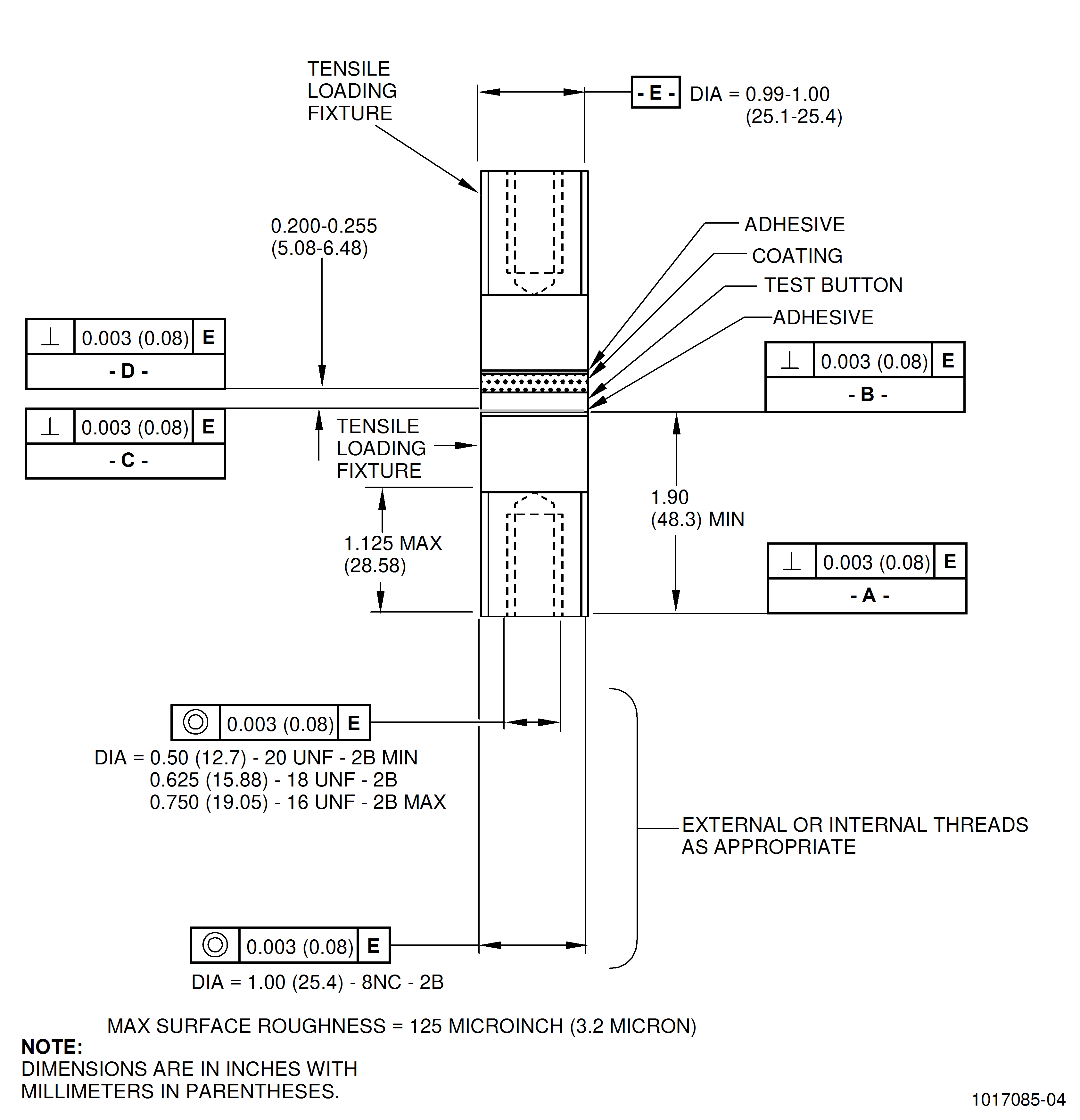
| This procedure describes the method, test specimens and special fixtures required for determining the bond tensile strength of thermal spray coatings when specified in the repair or in TASK 70-70-00-700-001, Testing and Quality Analysis. Use this test procedure when specified in the applicable thermal spray coating procedure. For testing, either a coated tensile button or a coated tensile loading fixture is permitted for tensile evaluation. |
| 2 . | Equipment. |
| Subtask 70-71-01-700-021 |
| A. | Tensile testing machine. |
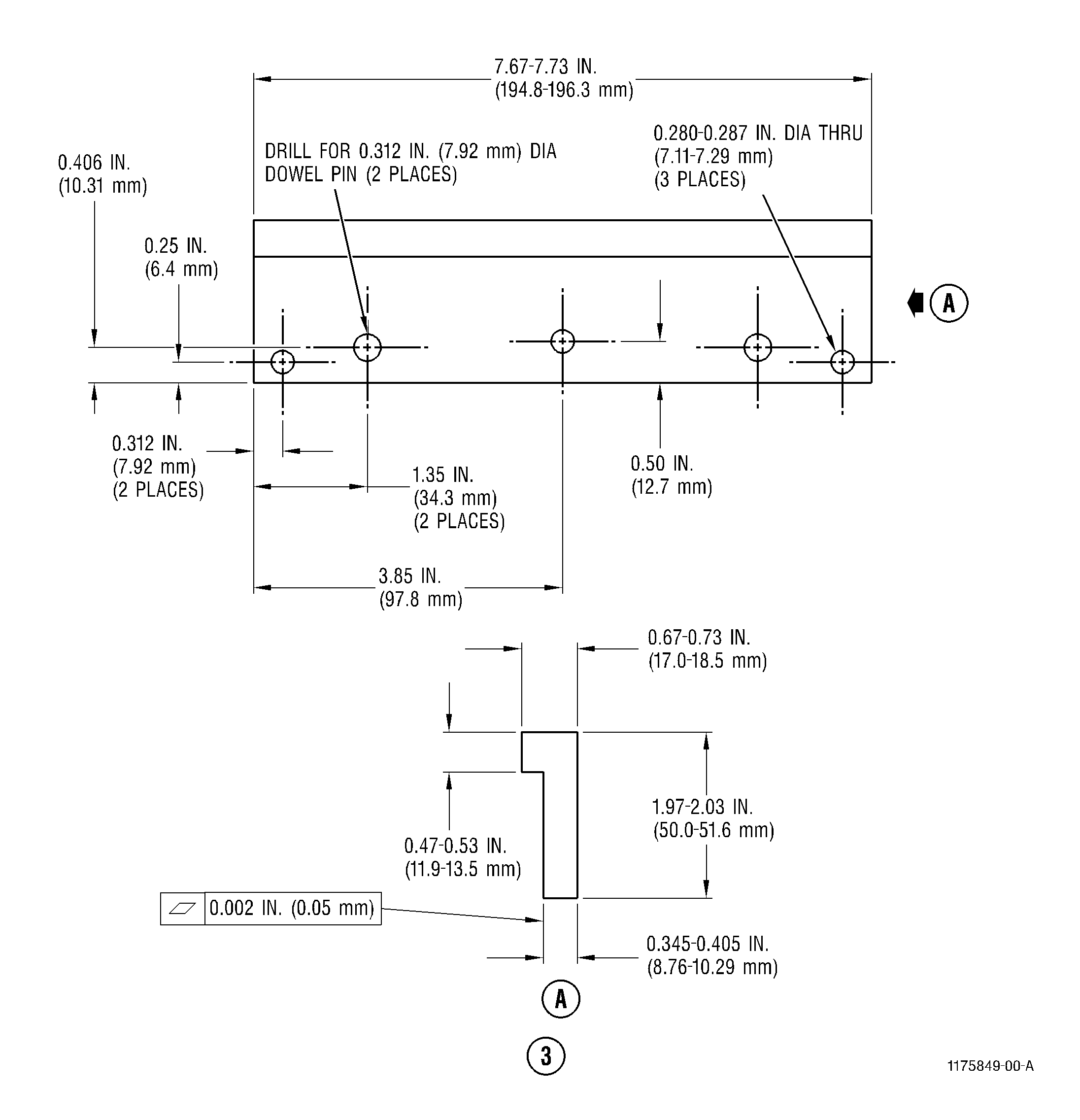
| B. | Tensile bond test assembly fixture per Figure 3 or Figure 2. |
| C. | Tensile bond test specimen per Figure 1. |
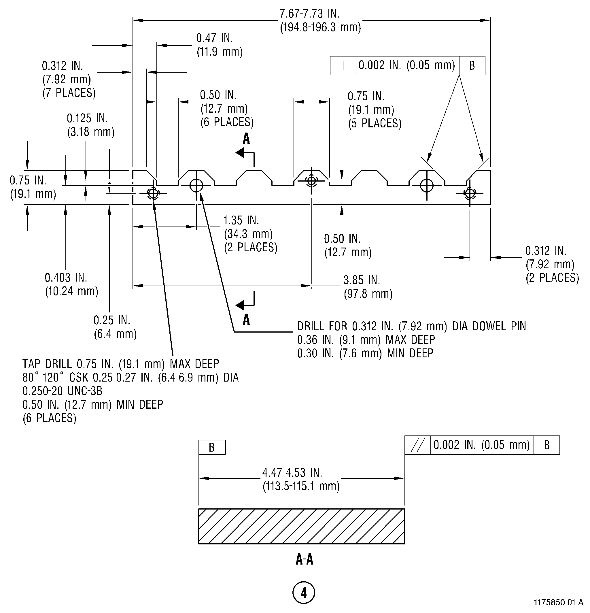
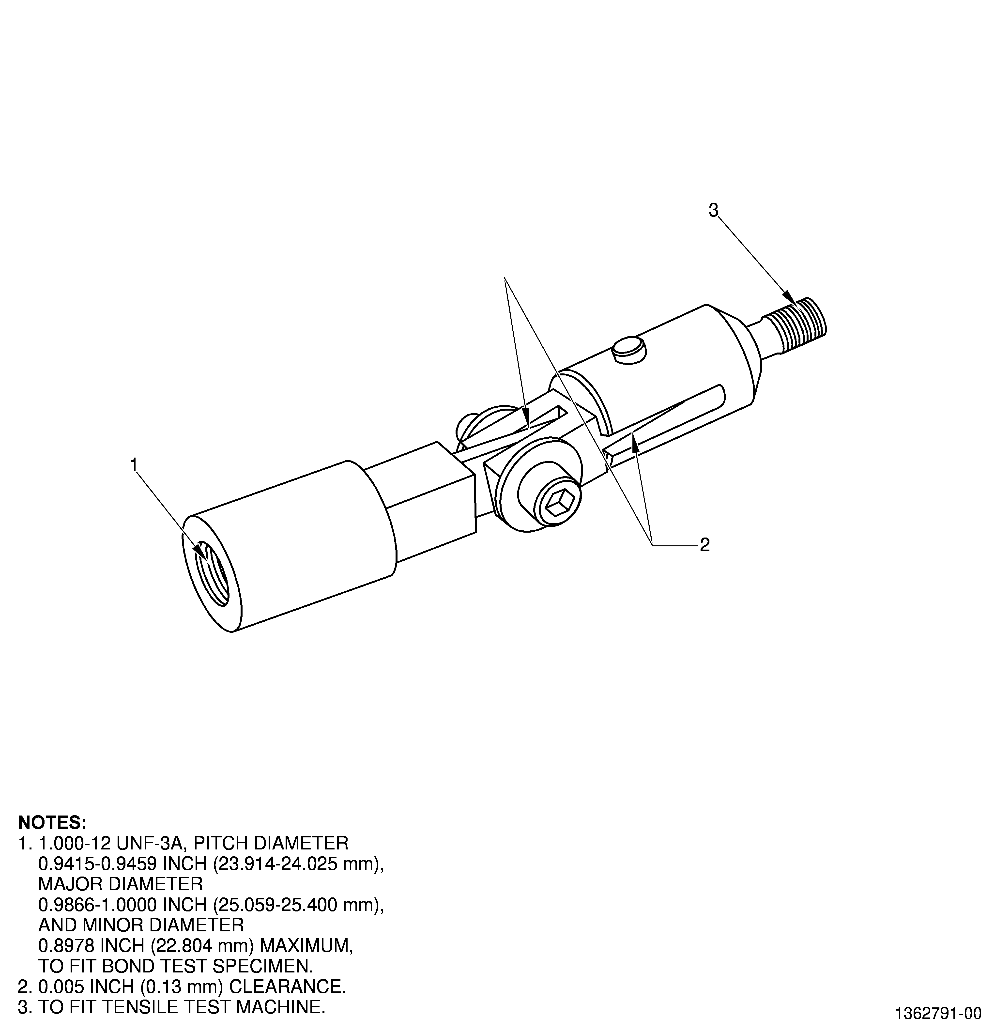
| D. | Adapter used for attaching the bond test specimens to the tensile test machine per Figure 4. |
| 3 . | Materials. |
| Subtask 70-71-01-700-022 |
|
| NOTE: |
|
| 4 . | Tensile Bond Test Assembly Fixture. |
| Subtask 70-71-01-700-023 |
| E. | Use the assembly fixture to align and assemble each test specimen. The test specimen can be either a coated loading fixture/uncoated loading fixture pair or a coated test button between two loading fixtures. The assembly fixture may be made of AISI 300-series stainless steel or an equivalent dent-resistant material. A suitable release agent, such as C10-013 , or equivalent, should be applied to the fixture to prevent adherence of the adhesive. See Figure 3 or Figure 2. |
| 5 . | Tensile Bond Test Specimen. |
| Subtask 70-71-01-700-024 |
| F. | Either test buttons or loading fixtures of the same material or a material having a similar composition (nickel, iron, cobalt, titanium base alloys, etc.) and hardness as the production part that they represent are used to test the bond strength of thermal spray coatings. Refer to 70-70-00-700-001 , Testing and Quality Analysis, Subtask 70-70-00-700-012 (paragraph 3.), Test Specimen Material - Table 2, for a cross reference of materials used for test specimens based on the alloy of the part being repaired. If loading fixtures are chosen for spraying, the uncoated piece of the test specimen can be made from material other than the production parts as long as the weight of the loading fixture is sufficient to assure accurate bonding while using of the gravity bond fixture and the tensile strength of the loading fixture material exceeds the value of the coating's to be tested and differences in thermal expansion is verified. If buttons are chosen for spraying, the tensile loading fixtures shown in Figure 1 can be made from a material other than the production parts. A suggested material is AISI 300 series stainless steel. Alternative materials can be chosen but differences in thermal expansion must be verified. |
| G. | The test specimen should be prepared as follows. See Figure 1. |
| (1) | Machine the test specimen (button or loading fixture) of the same material or a material having similar composition (nickel, iron, cobalt, titanium base alloys, etc.) and hardness as the production part to the dimensions shown (see Figure 1). Use at least three specimens per production part. |
| (2) | Process the specimens through the same coating surface preparation and coating application procedures as the production parts they represent. |
| (3) | Mask the outside diameter (OD) surface of the test specimens, being careful to avoid masking or touching any of the prepared surface. Remove all overspray on the OD of the test specimen after coating. |
| (4) | Mount the test specimens (minimum of three) with the production part in such a way they will receive the same application of thermal spray without obscuring the part. The coating must be at least 0.005 inch (0.13 mm) thick, and must not vary across the surface more than 0.003 inch (0.08 mm). Methods used to remove the coating to obtain the required thickness uniformity must not damage the coating or bond. |
| (5) | If you use test buttons, grit blast both faces of each button with the same process that was used to grit blast the part. If you use loading fixture pair, grit blast the one to be coated with the same process that was used to grit blast the part. This is usually done in accordance with TASK 70-49-00-340-013, Thermal Spraying. |
| 6 . | Assembly of Test Specimen. |
| Subtask 70-71-01-700-025 |
| H. | Prepare the test specimen as directed in the following paragraphs. Two loading fixtures are required for each test specimen. |
| (1) | Grit blast the uncoated faces of both loading fixtures and test buttons using 60-150 mesh aluminum oxide grit and the grit blast methods in TASK 70-21-04-120-A01, Cleaning Method No. 4 - Dry Abrasive Blast Cleaning. Use a very low pressure 20 to 40 psi (0.138 to 0.276 MPa). Degrease each fixture. |
| NOTE: |
|
| (2) | The tensile specimens can be prepared using the following adhesives listed in Table 1 with recommended/suggested curing cycles. |
| (a) | Use only film adhesives C01-103 or C01-136 for materials with a minimum tensile bond strength requirement of below 5500 psi (37.9 MPa). |
| (b) | If using a liquid adhesive C01-100 , C01-105 , or C01-146 , apply a uniform layer of adhesive to the necessary surfaces. If using the coated loading fixture/uncoated loading fixture pair, apply the adhesive to both faces of the loading fixtures. If using the test button, apply the adhesive to both faces of the test button and the mating faces of the loading fixtures. |
| (c) | If using the film adhesive C01-103 or C01-136 , cut or punch discs from the film sheet that are the same diameter as the tensile specimen. Place a disc between the coated loading fixture/uncoated loading fixture pair or on each side of the button between the uncoated loading fixtures. |
| NOTE: |
|
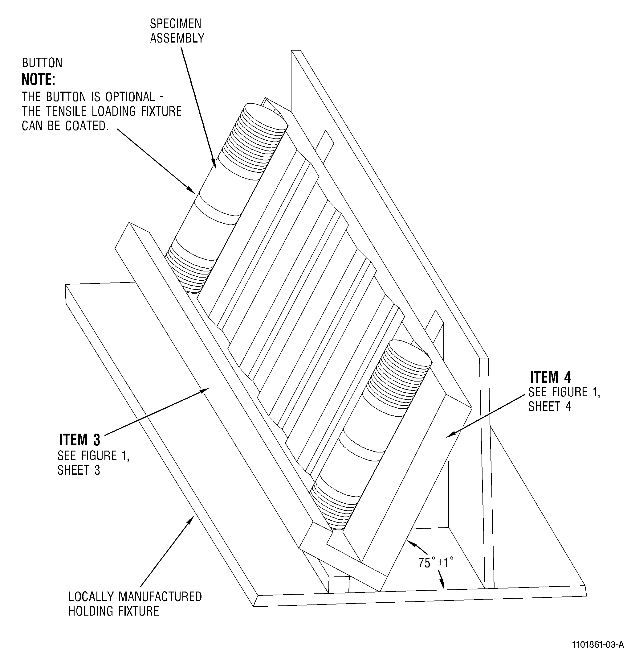
| (3) | Either a pressure (Figure 3) or gravity (Figure 2) curing fixture may be used for curing of the assemblies at temperature if the adhesive used is film adhesive C01-103 or C01-136. Gravity curing fixture (Figure 2) must be used for curing of the assemblies at temperature if the adhesive used is liquid type adhesive C01-100, C01-105, or C01-146. |
| (a) | An adhesive-only specimen should also be included in the fixture. This will consist of a specimen with only adhesive between the two loading fixtures. This should pull at 10000 psi (68.9 MPa). |
| NOTE: |
|
| (b) | For the gravity fixture (Figure 3) alignment is critical. Inspect the surface of the grooves in the loading fixtures to insure there are no dents or raised areas that could prevent proper alignment of the assemblies. Place the loading fixture threads down into the fixture followed by either adhesive-button-adhesive-loading fixture or adhesive-loading fixture depending on the choice of specimens for spraying. |
| (c) | For the gravity fixture (Figure 3) an alternate cure angle of 60 degrees ± 1 degrees is permitted in addition to the cure angle of 75 degrees ± 1 degrees shown in Figure 3. |
| (d) | For the pressure fixture, prepare the test specimen with the loading fixtures and adhesive as described earlier and place the assemblies in the fixture of Figure 3. Tighten the clamping screws to a suggested value of 35-40 lb in. (4.0 - 4.5 N·m) of torque. This will apply approximately 900-1000 psi (6.2-6.8 MPa) pressure on specimen. Check for proper alignment before curing. The pressure settings are recommended as a starting point. If the adhesive is continually pulled out between the button/loading fixture, a reduction in torque may be necessary. If adhesive-only specimens fall below 8000 psi (55.2 MPa), a change in pressure may also be required. |
| (4) | Cure the assemblies in the fixture at the suggested time/temperatures listed in Table 1 or as recommended by the manufacturer directions. Cure time is dependent upon the cure temperature. Other factors affecting curing are size/material of your curing fixture and tensile fixtures, power/capacity of your oven, etc. Using a thermocouple attached to the curing fixture or a dummy tensile assembly is highly recommended. |
| The curing fixture should cool to a temperature that allows handling of the material without gloves before removing the tensile assemblies from the fixture. |
| (5) | After curing, carefully remove any residual adhesive from surfaces adjacent to the bond area by sanding with 180-grit abrasive paper or cloth or abrasive pads (C10-117) and (C10-010). Mount the test specimen between centers, and check concentricity and alignment with a dial indicator or comparator. Check at each loading fixture, 0.125 inch (3.18 mm) from the adhesive bond. Runout must be within 0.015 inch (0.38 mm) FIR. |
| NOTE: |
|
| 7 . | Test Procedure. |
| Subtask 70-71-01-700-026 |
| I. | The tension testing machine shall be capable of applying an increasing tensile load at a constant rate of 940 to 1100 pounds (4.18 to 4.89 kN) per minute or at a constant rate of cross-head travel of 0.030 to 0.050 inch (0.76 to 1.27 mm) per minute. The test specimen shall be at room temperature when tested. Perform the test as follows: |
| (1) | Mount and align the test specimen in the tensile test machine so that no bending or twisting strain will be exerted on the specimen. An adapter must be used for attaching the bond test specimens to the tensile test machine in accordance with Figure 4 or equivalent. |
| (2) | Apply a tensile stress to each test specimen at a constant rate between 1200 and 1400 psi (8.27 and 9.65 MPa) per minute or at a constant rate of cross-head travel of 0.030 to 0.050 inch (0.76 to 1.27 mm) per minute until rupture occurs. ASTM C-633 is an acceptable test method. |
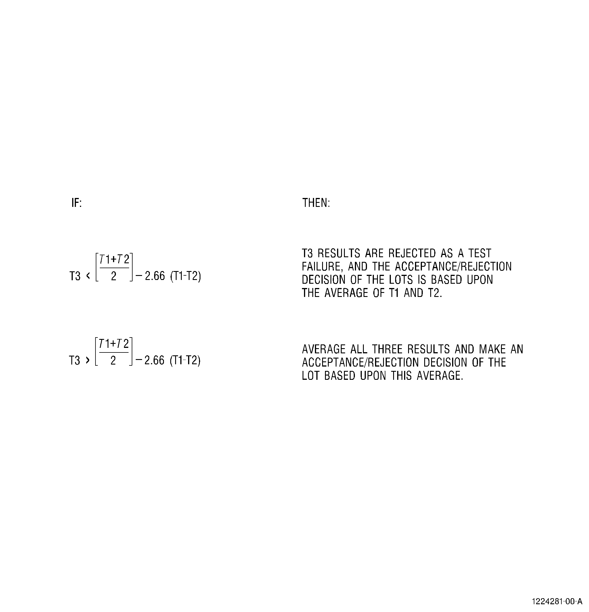
| (3) | Record rupture points for each of the three (or more) test specimens. The tensile bond strength average shall be determined from the property values of three coated specimens tested. The average shall be calculated using the following procedure: |
| (a) | Identify the highest result as T1, psi (MPa). |
| (b) | Identify the median result as T2, psi (MPa). |
| (c) | Identify the lowest result as T3, psi (MPa). |
| (d) | Use the identified values of T1, T2, and T3 in the equation show in Figure 5 to evaluate the specimens. |
| (4) | Examine the rupture-surface of each test button under 20-30 power magnification to determine if the failure is on epoxy or coating break. If a substantial epoxy failure is present due to a cause such as insufficient curing, retesting may occur if additional buttons are available. |
| NOTE: |
|