| COMMERCIAL ENGINE STANDARD PRACTICES MANUAL | Dated: 01/16/2023 | |
| SPM 70-71-04 METALLOGRAPHIC EVALUATION OF THERMAL SPRAY COATINGS | ||
| COMMERCIAL ENGINE STANDARD PRACTICES MANUAL | Dated: 01/16/2023 | |
| SPM 70-71-04 METALLOGRAPHIC EVALUATION OF THERMAL SPRAY COATINGS | ||
| TASK 70-71-04-700-005 |
| 1 . | General. |
| A. | This procedure describes the method of preparation and the evaluation criteria used to determine the integrity of thermal spray coatings as required per the shop manual or TASK 70-70-00-700-001, Testing and Quality Analysis. |
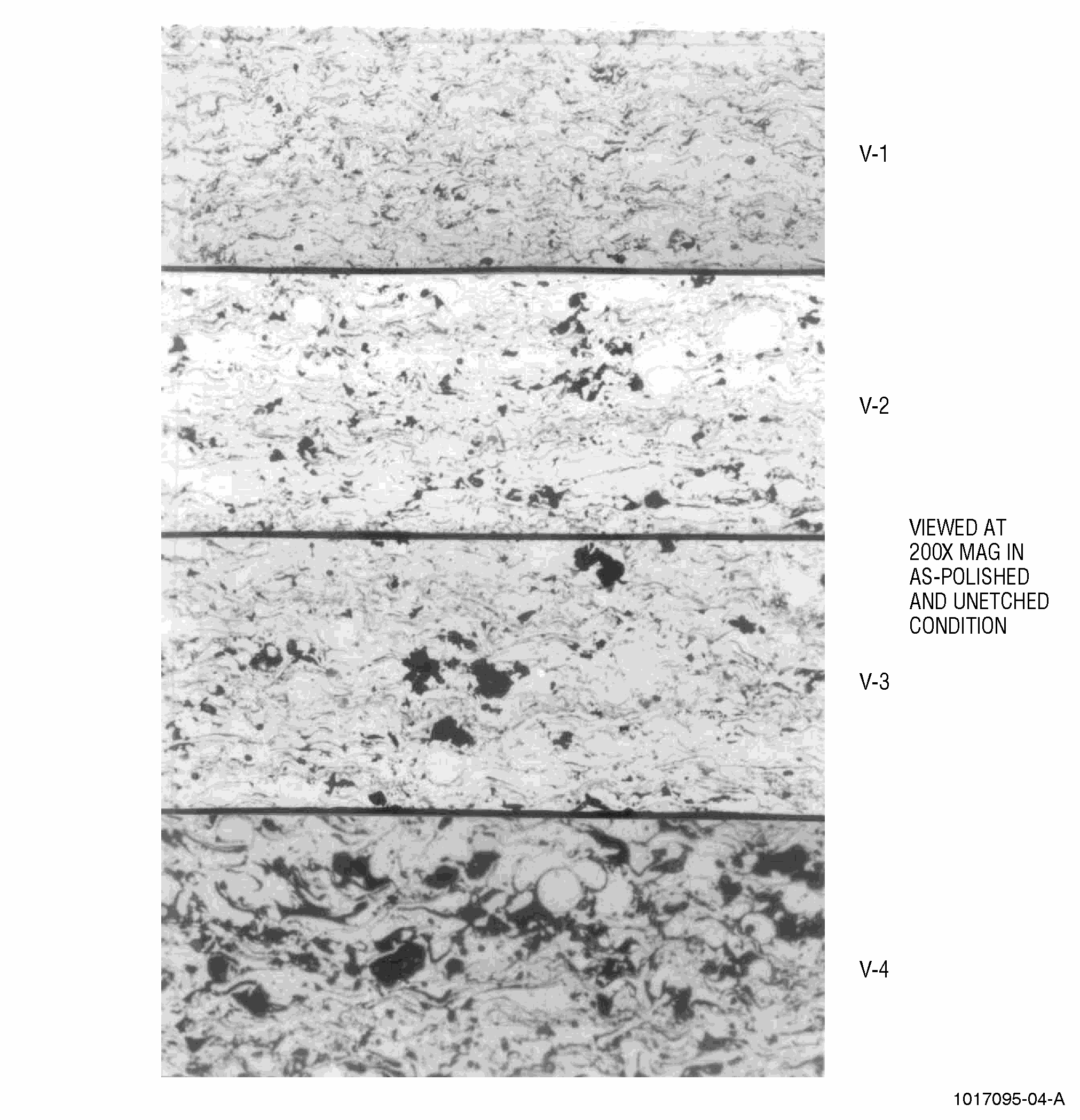
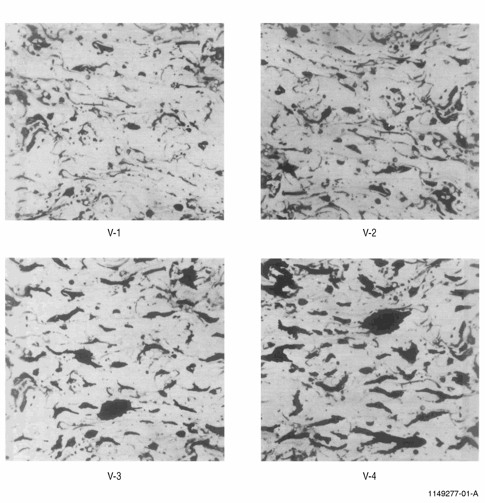
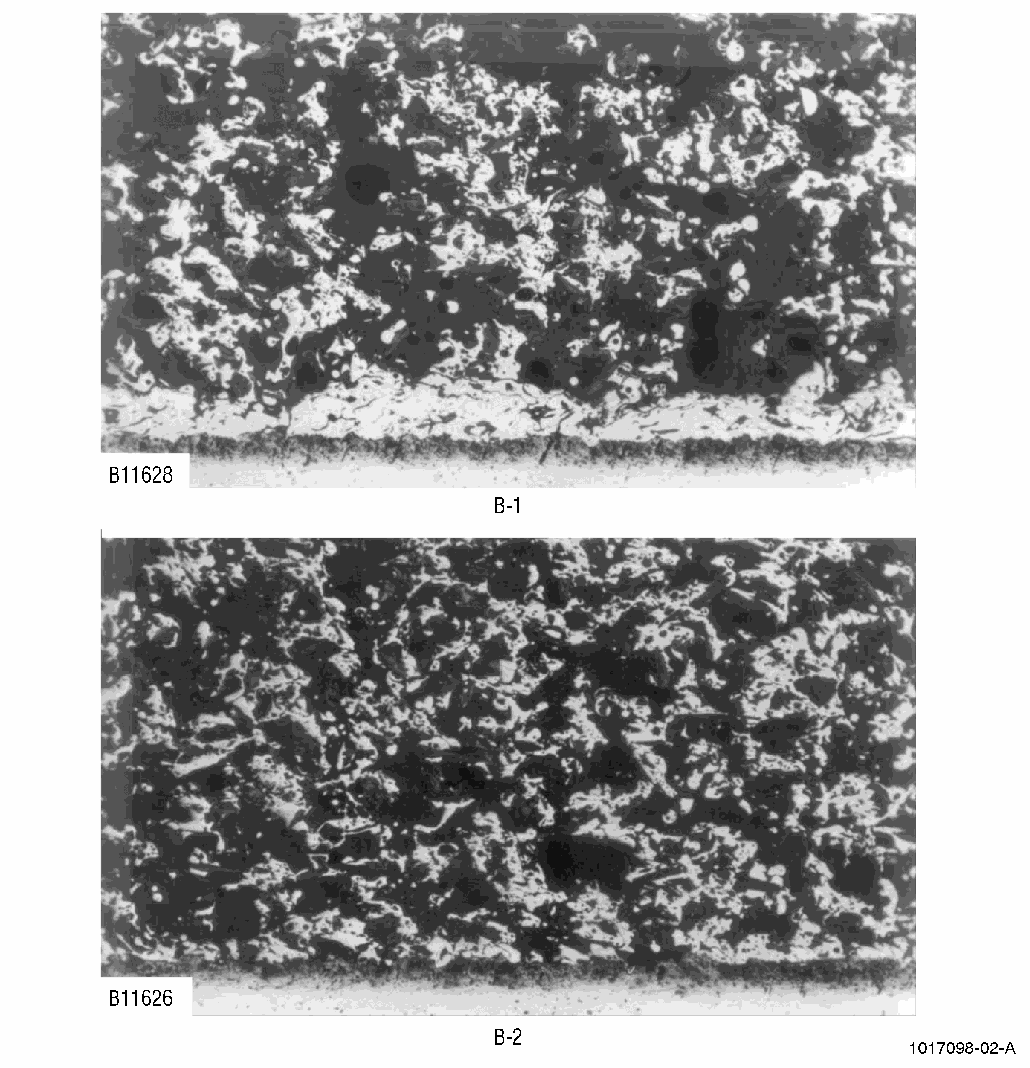
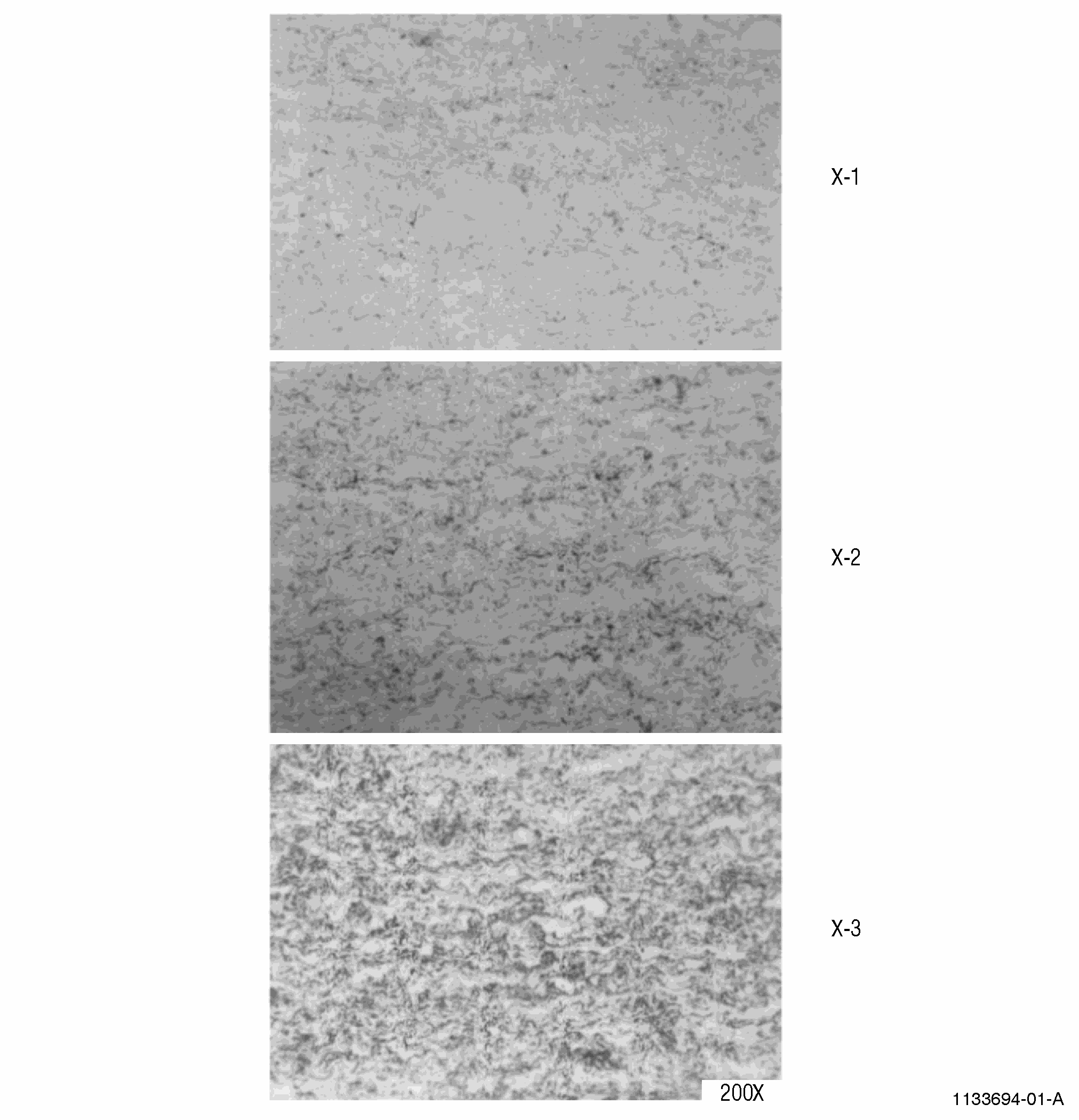
| B. | The most expedient method of detecting voids, oxide inclusions, unmelted particles, phase separation, and other metallurgical deficiencies in thermal spray coatings is by the microscopic comparison of the test specimen with the photomicrograph of a standard of known quality. |
| C. | The preparation of test specimens and the interpretation of photomicrographs requires considerable experience and practice, as well as complete familiarity with the particular equipment available in a given laboratory. Recognizing this inherent diversity, the following text presents only those practices for the guidance of the metallographer that have proven generally satisfactory in the preparation of coated specimens. For example, training is available from: |
| (USA) Metcut Research. Refer to the List of Suppliers in Step 4 of 70-80-00. |
| Deleted. |
| This training will assist the metallographer in developing effective, equivalent procedures to evaluate thermal spray coatings. |
| 2 . | Equipment. |
| Subtask 70-71-04-700-051 |
| D. | Sectioning equipment. Refer to Subtask 70-71-04-700-053, Preparation of Specimens. |
| E. | Grinding/polishing equipment. Refer to Subtask 70-71-04-700-053, Preparation of Specimens. |
| F. | Consumables. Refer to Subtask 70-71-04-700-053, Preparation of Specimens. |
| G. | Microscope and associated tools. |
| CAUTION: |
|
| H. | Photostandards. High quality photostandards referenced in Table 3 may be obtained through the Customer Service Center - GE Aviation Operations Center (AOC). Refer to the List of Suppliers in Step 4 of 70-80-00. |
| NOTE: |
|
| 3 . | Preparation of Specimens. |
| Subtask 70-71-04-700-053 |
| I. | General |
| (1) | Metallographic preparation of thermal spray samples involves the preparation of a composite specimen composed of the coating and substrate material. Coating types can vary from soft porous abradables to dimensional restoration metal build-ups to hard face materials. Many coatings with similar properties can be prepared using a universal standard method. However, materials at the soft or hard end of the spectrum may necessitate special considerations. |
| (2) | Methods developed for metallic-only samples can be used for coating samples with two important considerations: |
| (a) | Coatings are usually more heterogeneous in nature than (for example) wrought or cast metals. |
| (b) | Coatings can be more sensitive to damage (such as smearing and pullout) during preparation. |
| (3) | These considerations substantiate the recommendation of semi-automated or automated grinding/polishing machines for thermal spray materials in lieu of manual polishing for consistent reproducibility and control of process parameters. |
| J. | Sectioning |
| (1) | Many spray shops eliminate the need for sectioning by spraying a small sample that can be mounted and then ground/polished to an appropriate plane for review/interpretation. |
| If sectioning is required, two common methods are abrasive wheel cutting or diamond wire cutting. The following considerations should be made: |
| (a) | Always section with the cut force from coating to substrate. |
| (b) | Use minimal clamping pressure and, if possible, a soft cushion such as wood to secure the specimen for sectioning. This will minimize possible cracking of the coating and alteration of the structure. |
| (c) | When sectioning, the usage of a thin sectioning wheel will minimize damage which must be removed in subsequent steps. |
| (d) | Apply minimum pressure during actual cutting to minimize possible overheating of the specimen and alteration of the structure. |
| (e) | Wheels which are comprised of a binder that breaks down readily exposing fresh cutting surfaces are usually best for a wide range of coatings. |
| (f) | For the choice of sectioning method, it is critical to maintain written procedures and identify the critical parameters requiring control for consistent techniques. |
| K. | Cleaning |
| (1) | Cleaning is an important step after sectioning; cleaning removes all contaminates from the surface of the specimen and removes any fluids that may have penetrated into the coating of the material, especially porous materials. Recommended methods of cleaning may include the following or any combination thereof: |
| (a) | Washing with soap and water. |
| (b) | Brushing or soaking of sample in solvent-like materials such as acetone/alcohol followed by application of heat with a heat gun or hotplate to drive off any internal absorption. |
| (c) | Cleaning of sample by performing an initial/extra vacuum step (if using vacuum impregnation in mounting) to volatilize any entrapped materials. |
| L. | Mounting |
| (1) | Mounting is a very critical step for metallography of coatings because this procedure serves to hold the sample together during grinding/polishing. This is especially true for porous materials. |
| (2) | Methods for mounting of coating materials are suggested below and sometimes used together. |
| (a) | Hot Mounting (in a press). |
| (b) | Cold Mounting (can be assisted by heat, vacuum impregnation, or pressure impregnation). |
| (3) | Suggested mounting materials for coatings are: |
| (a) | Hot mount epoxies. |
| (b) | Cold mount epoxies. |
| (4) | Choice of mounting procedure/material should be driven by: |
| (a) | Time available for mounting. |
| (b) | Size/level of porosity in coating and degree of interconnected porosity. |
| (c) | Required viscosity of epoxy for impregnation of porosity, if important. |
| (d) | Hardness of coating vs. mounting material. |
| (5) | For porous coatings like abradables, thermal barrier coatings (TBC), and other materials, cold mounting with vacuum impregnation and/or pressure impregnation is recommended. The viscosity of the cold mount epoxy will be important if porosity in the coating is small and difficult to impregnate. |
| (6) | A well impregnated sample will also show less tendency towards pullout of phases and microstructure damage. |
| (7) | For the choice of mounting method/material, it is critical to maintain written procedures and identify the critical parameters requiring control for consistent techniques. |
| M. | Grinding/Polishing |
| (1) | There are many methods/formats available for preparation of coating samples primarily encompassing traditional grinding papers and the relatively new disc systems. |
| (2) | Critical parameters that must be considered/controlled in preparation are: |
| (3) | When choosing a preparation method for a coating type, the following items must be considered: |
| (a) | Aggressiveness of grinding/cutting action. |
| (b) | Hardness of coating vs. abrasive type. |
| (c) | Tendency of coating phases to be pulled out. |
| (d) | Composition of coating phases to prevent chemical attack. |
| (e) | Degree of impregnation from mounting. |
| (f) | Tendency of smearing (closing porosity). |
| (4) | When initial grinding is performed, care must be taken to remove cut-off damage if the sectioning step was used. If an as-sprayed coupon was mounted, remove sufficient material to eliminate any coating edge effects. Many laboratories use aluminum oxide grinding stones for removal of this initial material. |
| (5) | Polishing formats for coatings usually involve moderate to extended times on no-nap clothes followed by short finishing steps on higher-nap clothes. Care must be taken to avoid over polishing with colloidal silica in the final polishing steps. |
| (6) | Typical procedures involving both grinding paper and disc formats are shown in Tables 1 and 2. These procedures may require modification for different coatings and equipment available in specific laboratories. |
| (7) | Equipment is available that will control some or all of the critical parameters. These semi-automatic/automatic machines, in conjunction with written procedures that monitor/control critical parameters, will result in consistent and reproducible results. |
| (8) | Periodic calibration and maintenance of the equipment will assure reliability and repeatability. |
| N. | Consumables |
| (1) | Consumables used in the metallographic process are obviously very critical to the final result. It is important to obtain high quality materials to insure reproducibility and consistent results. Although consistency from a reliable manufacturer is usually good, products from company to company can vary due to lack of standards within the industry. Changes in consumable suppliers should be considered carefully. It is suggested that if changes are made to an already established procedure with new consumables, some trial samples should be run to insure similar performance and results. Some issues that can occur are: |
| (a) | The amount of grit deposited on a grinding paper can vary resulting in removal differences during grinding. |
| (b) | The amount of diamond in a suspension can vary resulting in removal differences during polishing. |
| (c) | The distribution of particle size in a suspension can vary resulting differences in materials removal and possibly scratch retention. |
| (d) | Changes in the type of carrier in a suspension can affect material removal rate and performance. This may also affect the corrosive potential of the solution. |
| (e) | Over-polishing can result with the excessive time/usage of colloidal silica. |
| O. | Use of Physical Metallographic Standards |
| (1) | A relatively new concept is the use of metallographic standards similar to hardness blocks for Rockwell machines. For daily calibration of the hardness tester, a hardness block is tested to insure the machine is reading within the range of the block. A similar principle can be used with known metallographic mounts or standards. |
| (2) | Changes can occur in preparation machines and consumables without the metallographer detecting the variance. Preparation with semi-automatic/automatic machines usually involves grinding/polishing of more than one mount. If the metallographer has a known sample from either a good spray run in the past or possibly a Round Robin in the thermal spray industry, the metallographer can place that specimen in the rack before being run. If the results on the "known" sample are similar to previous values, it can be assumed that the procedure is under control. If results are different, something has changed in preparation and an investigation of the metallographic technique is in order. |
| (3) | This procedure is not suggested for every rack of mounts that is prepared. Some recommended situations may be: |
| (a) | Periodic sampling such as once every two weeks, or more frequent if the use of the machine is not on a daily basis. |
| (b) | Results indicate a failing spray run and the production group cannot identify a reason for the unacceptable values. |
| (c) | Introduction of new consumables of grinding/polishing methods. |
| (d) | Sources of these metallographic standards can be: |
| 1 | Internal company Round Robins between sites. |
| 2 | Participation in industry Round Robins. |
| 3 | Passing samples from previous spray runs that may have been reviewed and accepted by a company representative. |
|
|||||||||||||||||||||||||||||||||||||||||||||||||||||||||||||||||||||||||||||||||||||||||||||||||||||||||||||||||||||||||||||||||||||||||||||||||||||||||
|
|||||||||||||||||||||||||||||||||||||||||||||||||||||||||||||||||||||||||||||||||||||||||||||||||||||||||||||||||||||||||||||||||||||||||||||||||||||
| 4 . | Metallographic Evaluation. |
| Subtask 70-71-04-700-054 |
| P. | Definitions |
| (1) | The following definitions should be used for evaluation: |
| (a) | Interface Contamination |
| Embedded foreign particles or contamination between the base metal and the coating. This contamination may be in the form of base metal oxides, grit, or residual coating remaining from previous stripping operations. |
| (b) | Coating Contamination |
| Foreign material present in the coating. This contamination may be in the form of metallic or ceramic particles. These particles may come from nozzle hardware, contaminated powder feed systems, etc. |
| (c) | Transverse Crack |
| A linear or branched separation with random direction within the coating that must be greater than 0.002 inch (51 micrometers or 2 mil) to be ratable. Cracks are only ratable in a thermal barrier ceramic coating when greater than 0.005 inch (0.127 mm) in total length. Examination shall be performed at 200X. |
| (d) | Delamination |
| A separation or horizontal defect that follows, or is associated with, contour of the linear build-up or coating layers that must be greater than 0.010 inch (254 micrometers or 10 mil) to be ratable. For linear interface defects, see Separation. |
| (e) | Field of View (FOV) |
| A unit area as viewed or photographed using normal light microscopy. |
| A unit of measure to aid in evaluation to determine the percentage of occurrence for a particular condition. |
| (f) | Grit Blast Inclusion |
| Embedded abrasive particle associated with the substrate surface preparation. |
| (g) | Hardness |
| Resistance to deformation. |
| (h) | Integrity |
| Overall coating quality primarily associated with oxides porosity and unmelted particles. |
| (i) | Layering |
| Stratification of coating components or features. |
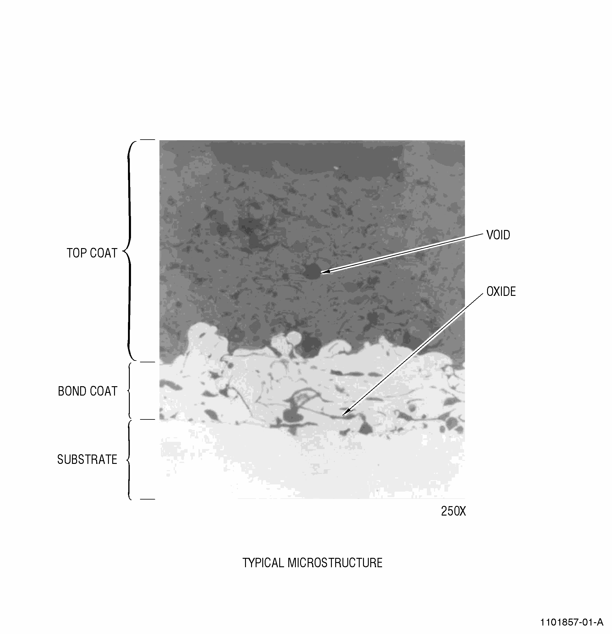
| (j) | Oxide |
| Oxidized coating constituent. |
| (k) | Oxide Clusters |
| Concentration of oxides that must be greater than 0.003 inches (75 micrometers) to be ratable. |
| (l) | Oxide Stringers |
| Linear oxides. |
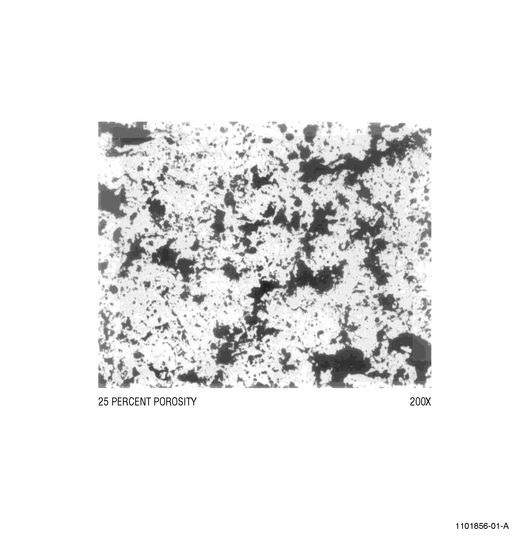
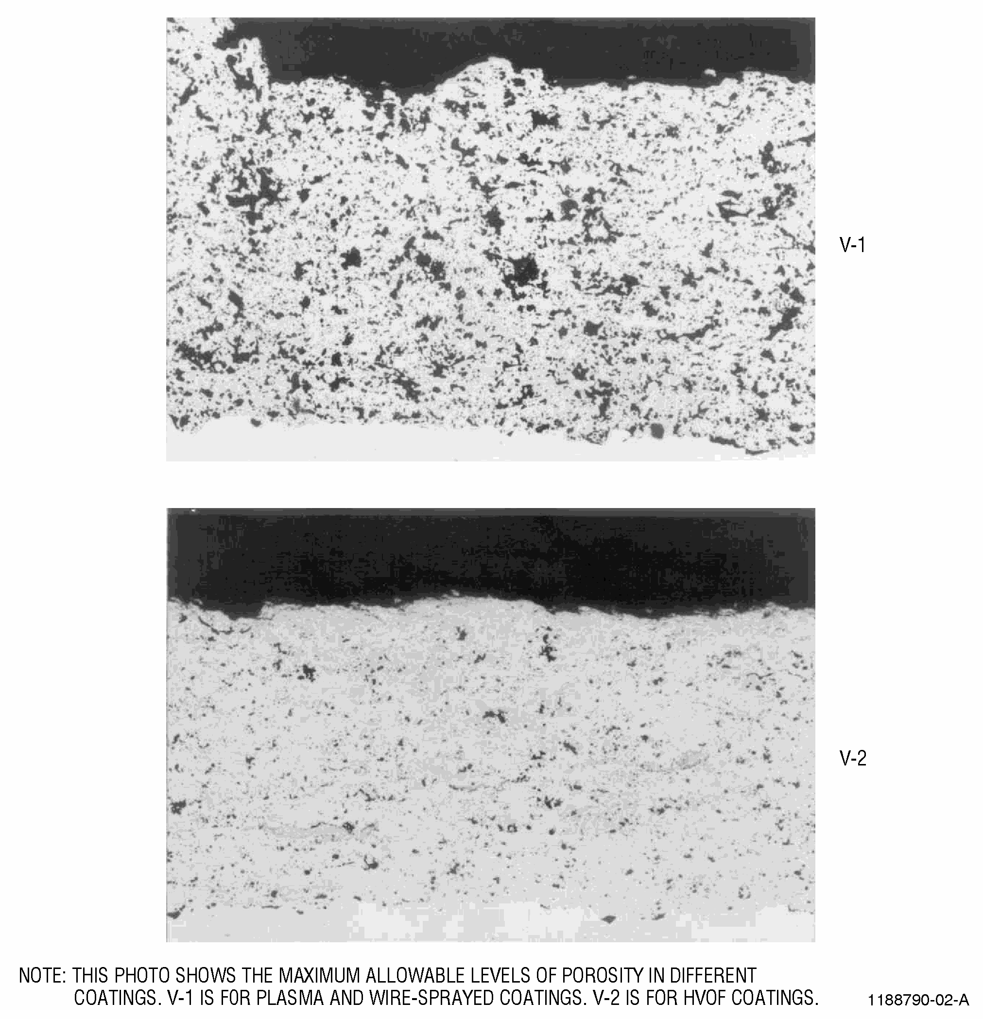
| (m) | Porosity |
| Typical holes within a coating. |
| (n) | Pull-out |
| Mechanically induced damage associated with metallographic preparation |
| (o) | Separation |
| A defect that follows, or is associated with, the contour of the interface. It must be longer than 0.005 inches (125 micrometers) to be ratable. For linear intracoating defects, see Delamination. |
| (p) | Straight-line Interface |
| A condition associated with insufficient roughening of the surface prior to spraying. |
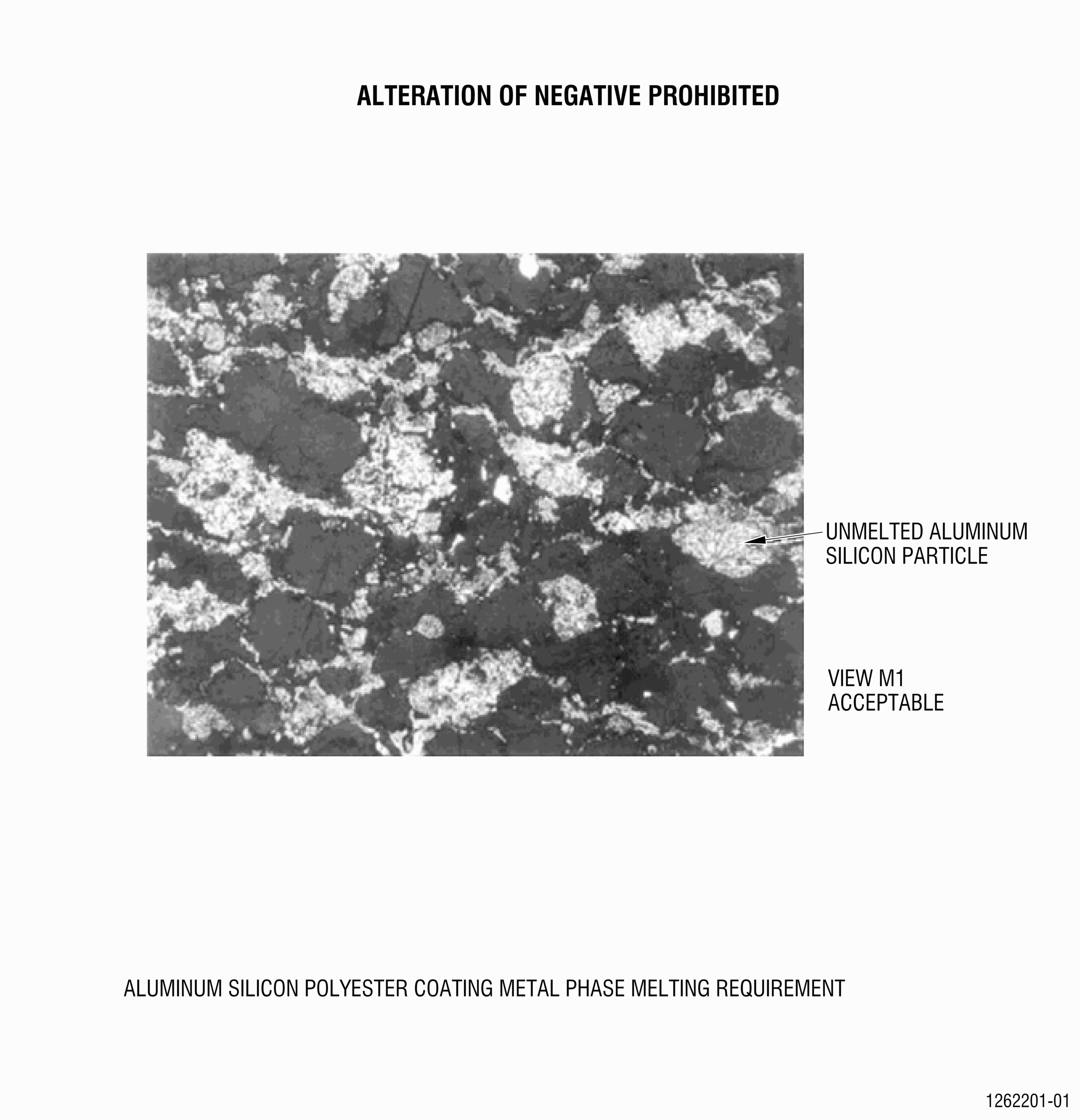
| (q) | Unmelted Particles |
| Unreacted powder particles contained within the coating matrix. These particles have a round or globular appearance (3:2 ratio), are not adhered to the surrounding coating matrix by any more than 25%, and are greater than 0.002 inch (50 micrometers) in any direction. |
| (r) | Uniformity |
| Homogenous distribution of coating constituents (e.g. phases, porosity, oxides, etc.). |
| Q. | Rules for Metallographic Evaluation of Coated Test Samples |
| (1) | Bondcoat Systems (Two areas): |
| (a) | Must review bond between bond and top coatings. |
| (b) | Must review bond between bond coat and substrate. |
| NOTE: |
|
| (2) | Transverse Coating Cracks: |
| (a) | Review for cracking. |
| All indications of less than 0.002 inch (51 micrometers) must not be considered a defect. |
| (b) | Defects shall be repolished and re-evaluated. |
| (3) | Delamination |
| (a) | Review for delaminations. |
| All indications of less than 0.010 inch (254 micrometers) in length must not be considered a defect. |
| (b) | Defects shall be repolished and re-evaluated. |
| (4) | Edge Effects |
| (a) | Do not evaluate coating areas less than 0.010 inch (250 micrometers) from the test piece edge of coating runout. |
| (5) | FOV (Field of View) |
| (a) | Shall be representative of a particular or predominate condition. |
| (b) | A periodic sampling across the coating sample. |
| (c) | When addressing specific rejectable conditions, they are to be characterized by measuring the affected fields of view. |
| (6) | Microhardness |
| (a) | Refer to Subtask 70-34-02-220-082 Vickers Hardness Testing, to measure the microhardness of coating. |
| (b) | Deleted. |
| (c) | Deleted. |
| (7) | Illumination |
| (a) | Bright field shall be used for comparison with photographic standards. |
| (8) | Magnification |
| (a) | Same as the Photomicrographic standards. |
| (9) | Mount Material |
| (a) | Cold mounting is preferable. |
| NOTE: |
|
| (10) | Repolishing/Regrinding |
| (a) | Repolishing is limited to two (2) times. This means a maximum total of three (3) preparation cycles is permitted, comprising the initial preparation and two (2) repolish cycles. Repolishing is only permitted for metallurgically induced defects such as cracks, delamination, separation, pull-out, phase contrast, and spalling. |
| (11) | Sample Size |
| (a) | Suggested panel size shall be 0.060 inch (1.5 mm) thick x 0.75 inch (19 mm) width x 1.5 inch (38.1 mm) length. |
| (b) | If minimal panel size is not practical, coated panels used for metallographic evaluation shall be large enough to avoid edge defects and cutting defects. |
| (c) | Minimum separation between cuts shall be 0.5 inch (12.8 mm). |
| (d) | Specimen shall be cut through the width. |
| NOTE: |
|
| (12) | Thickness |
| (a) | Coating thickness on metallographic test specimen shall have the same as-sprayed coating thickness as the part. |
| For qualification test specimens; coating thickness for metallographic investigation shall be 0.008-0.012 inch (200-300 micrometers) for a single coating. For a duplex coating, the bond coat shall be 0.003-0.008 inch (75-200 micrometers) and the top coat shall be 0.008-0.012 inch (200-300 micrometers). |
| (13) | In-between Condition |
| (a) | If the visual interpretation is in-between the rejectable and the acceptable photomicrographic standards, it must be rated to the lower (worst) condition. |
| (14) | Percentage of Field Rule |
| (a) | In rating a coating microstructure, the 5 percent cumulative feature ocurrence can be more than the level in photographic standards. If less than 5 percent of the views are more than the photographic standard, the coating metallography is acceptable. |
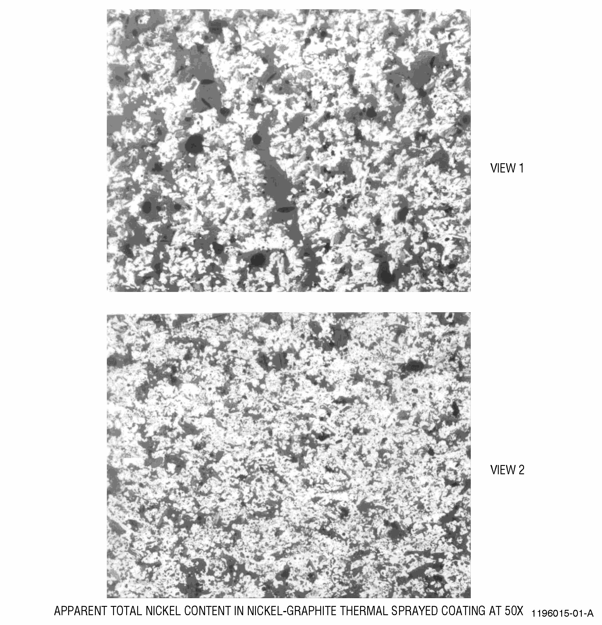
| R. | General Microstructure Evaluation |
| (1) | When specified by the Engine/Shop Manual, metallographic examination of the prepared specimen shall be made for the following other conditions: |
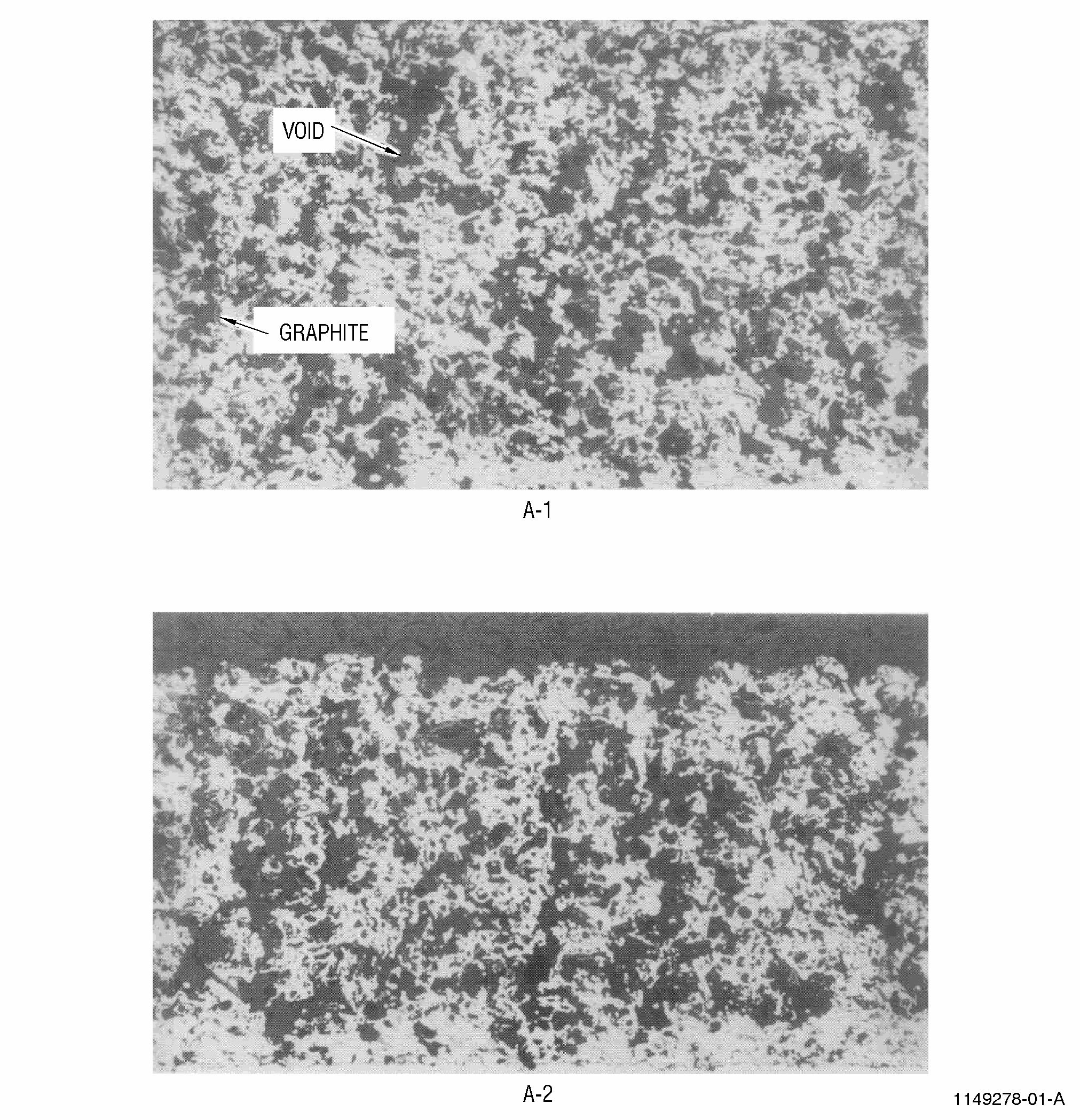
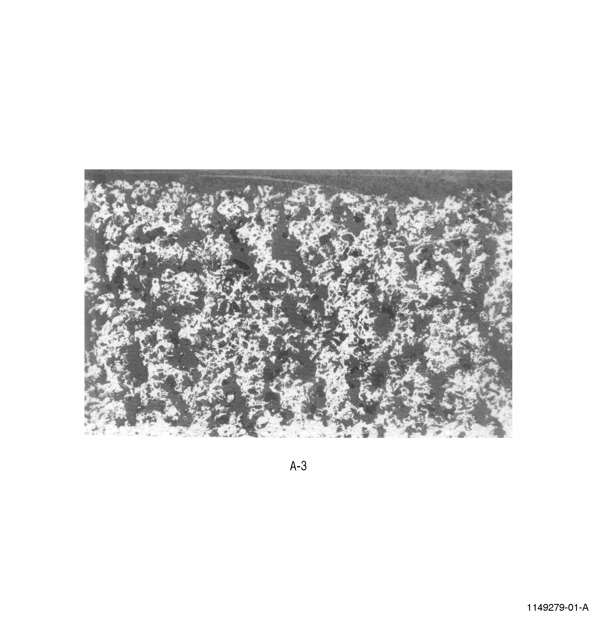
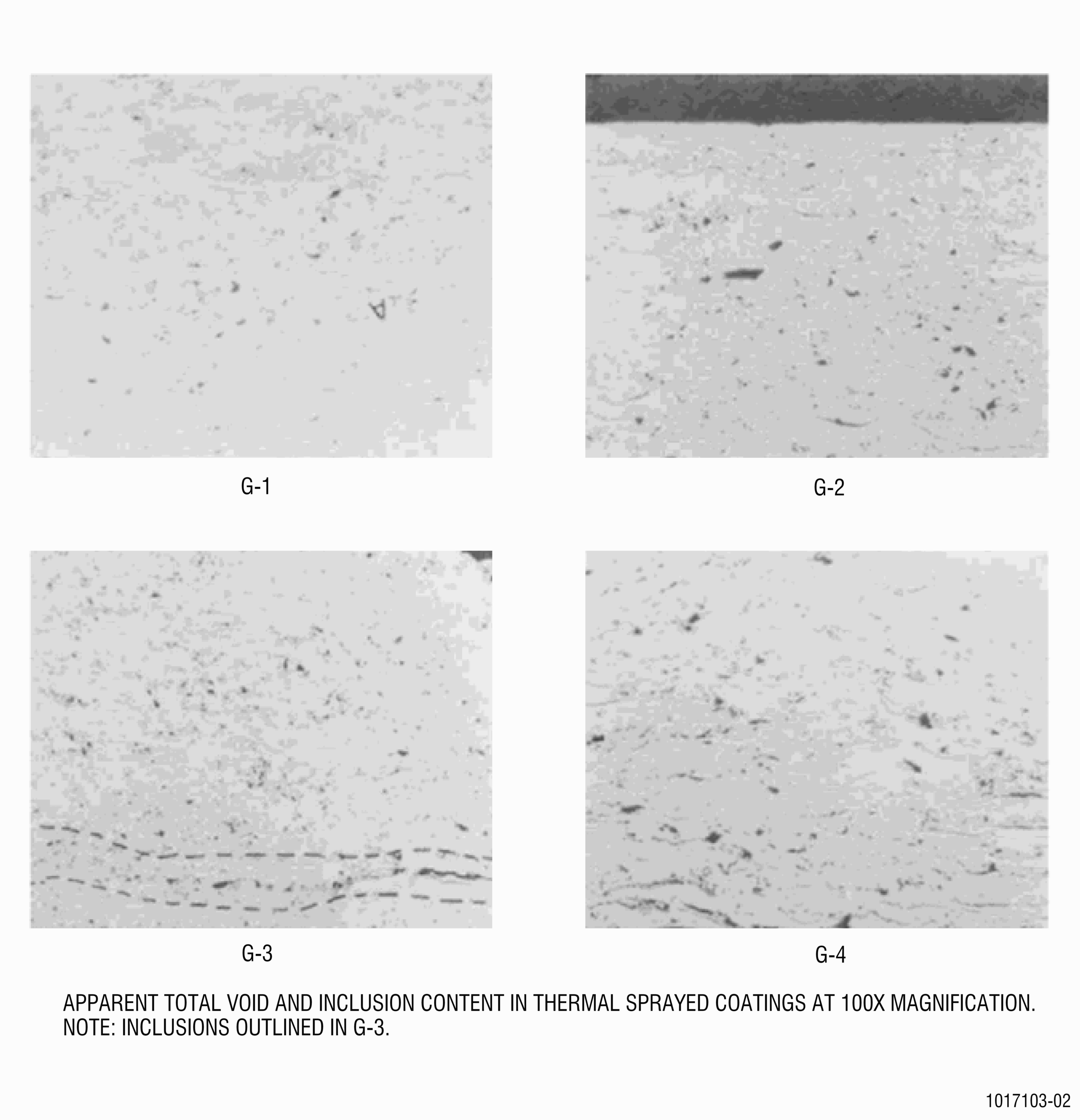
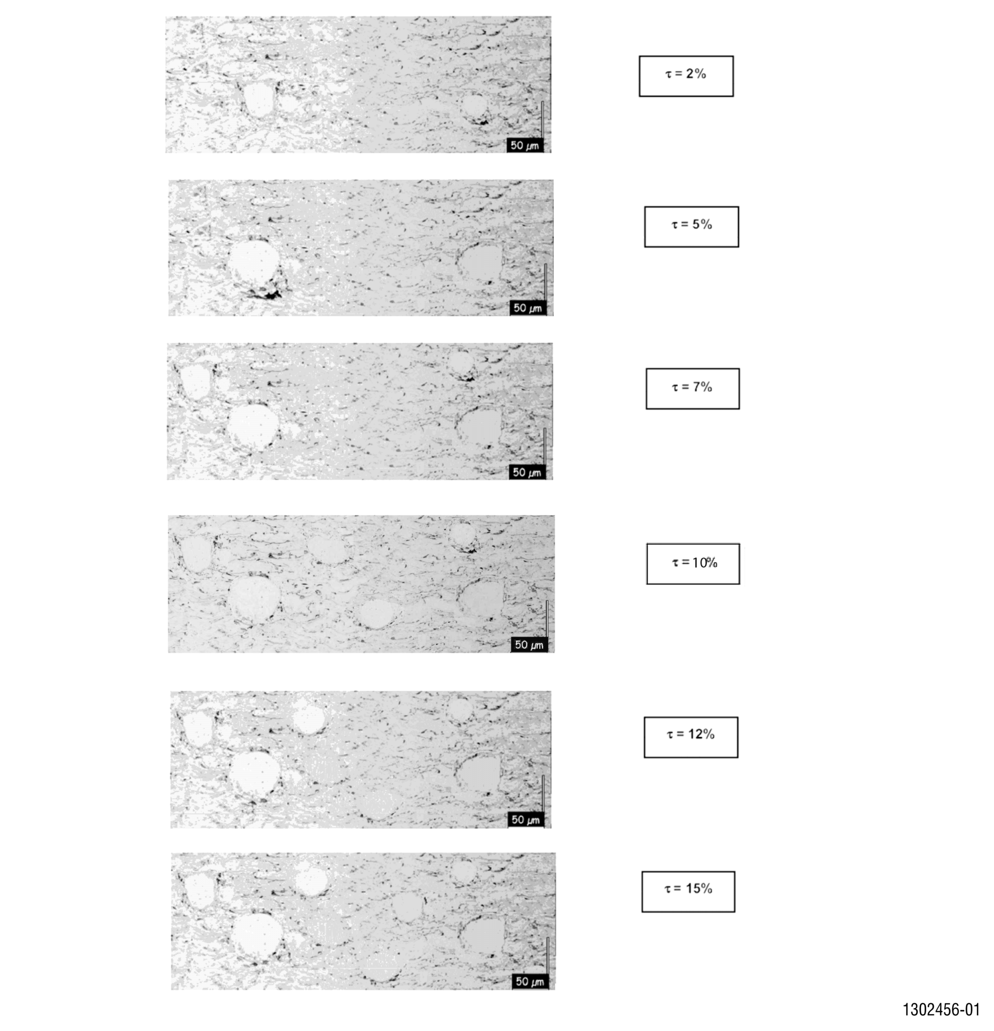
| (a) | Porosity. |
| Examine at 200-500X. Estimate visually, quantify by image analysis, quantify by grid count, or compare to appropriate photostandards. Porosity shall be uniformly distributed. |
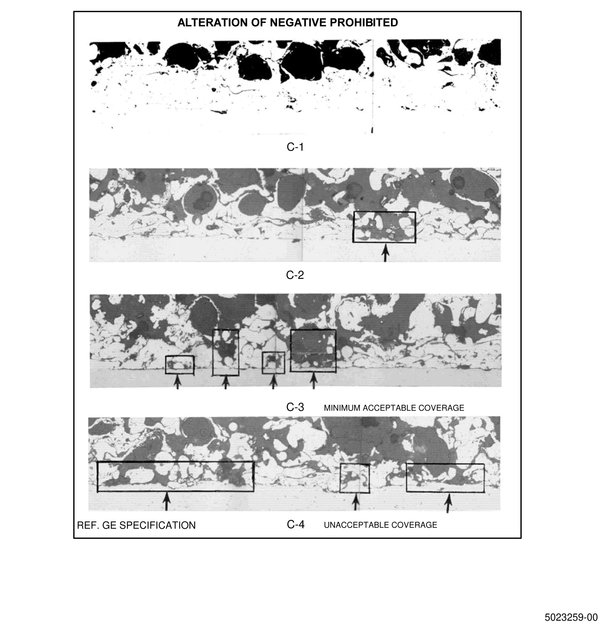
| (b) | Interface Contamination and Separation. |
| Examine at 200-500X for the presence of contamination. This may be in the form of oxides, grit, or residual coating from previous stripping operations. Estimate the percent of contamination for comparison to acceptance values in either number or photostandard format. The coating shall be free of interface separations as defined in 70-71-04. |
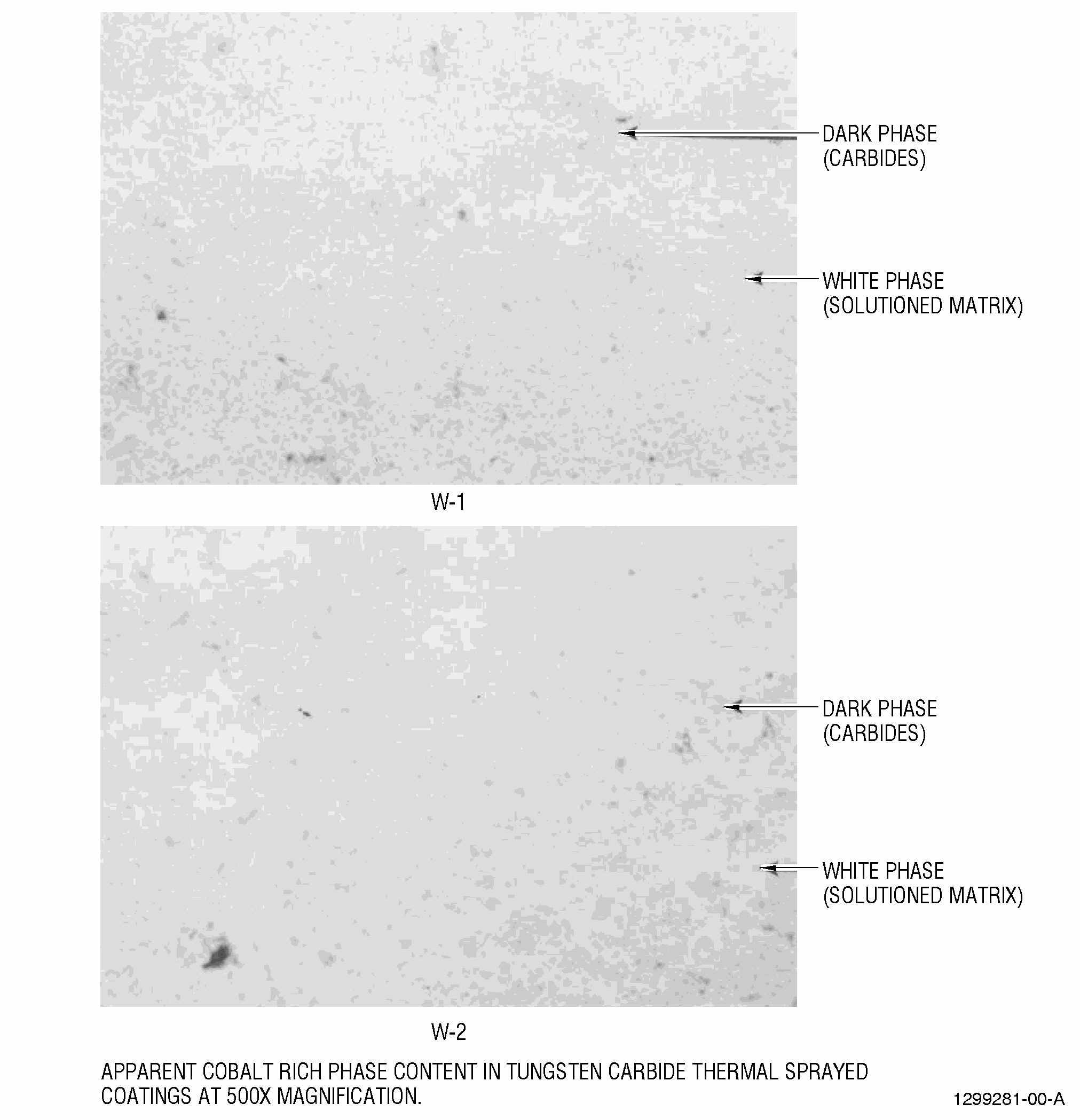
| (c) | Unmelts |
| Examine at 200-500X for the total percent of unmelts for comparison to acceptance values in either number or photostandard format. Unmelts can be associated with porosity and oxides. Ratable unmelts shall be determined by examination of size, shape, and bonding for each particle. |
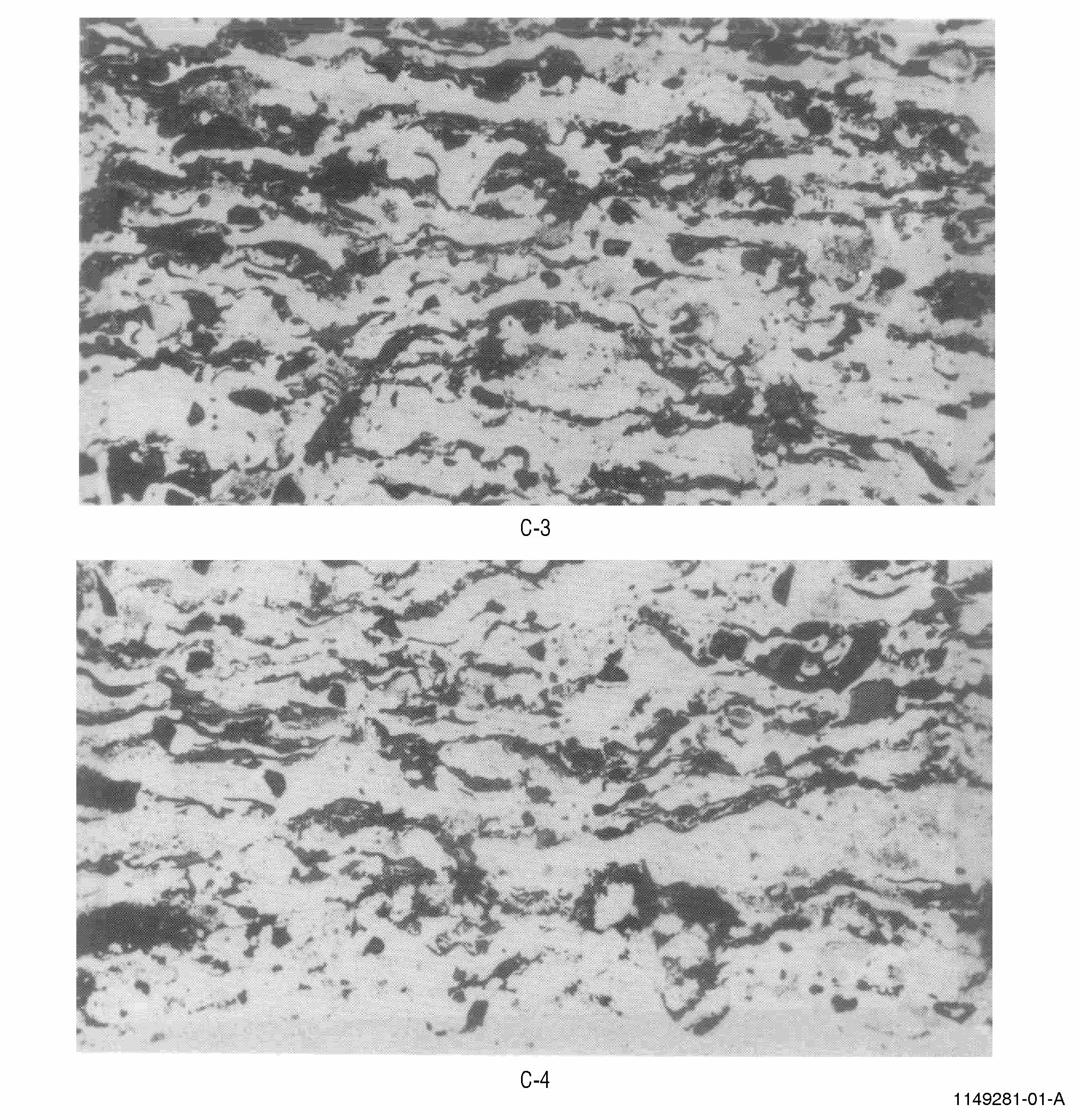
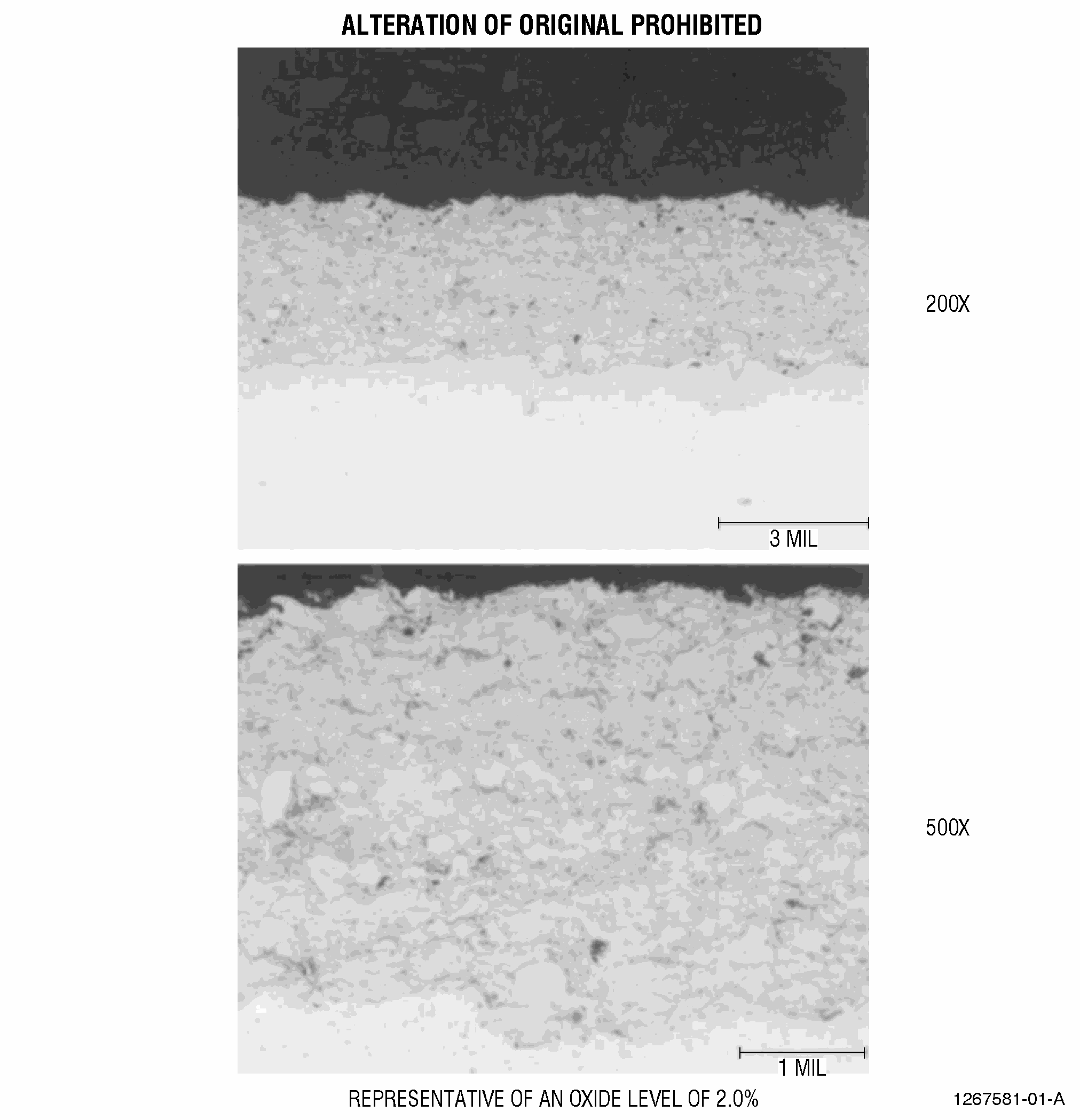
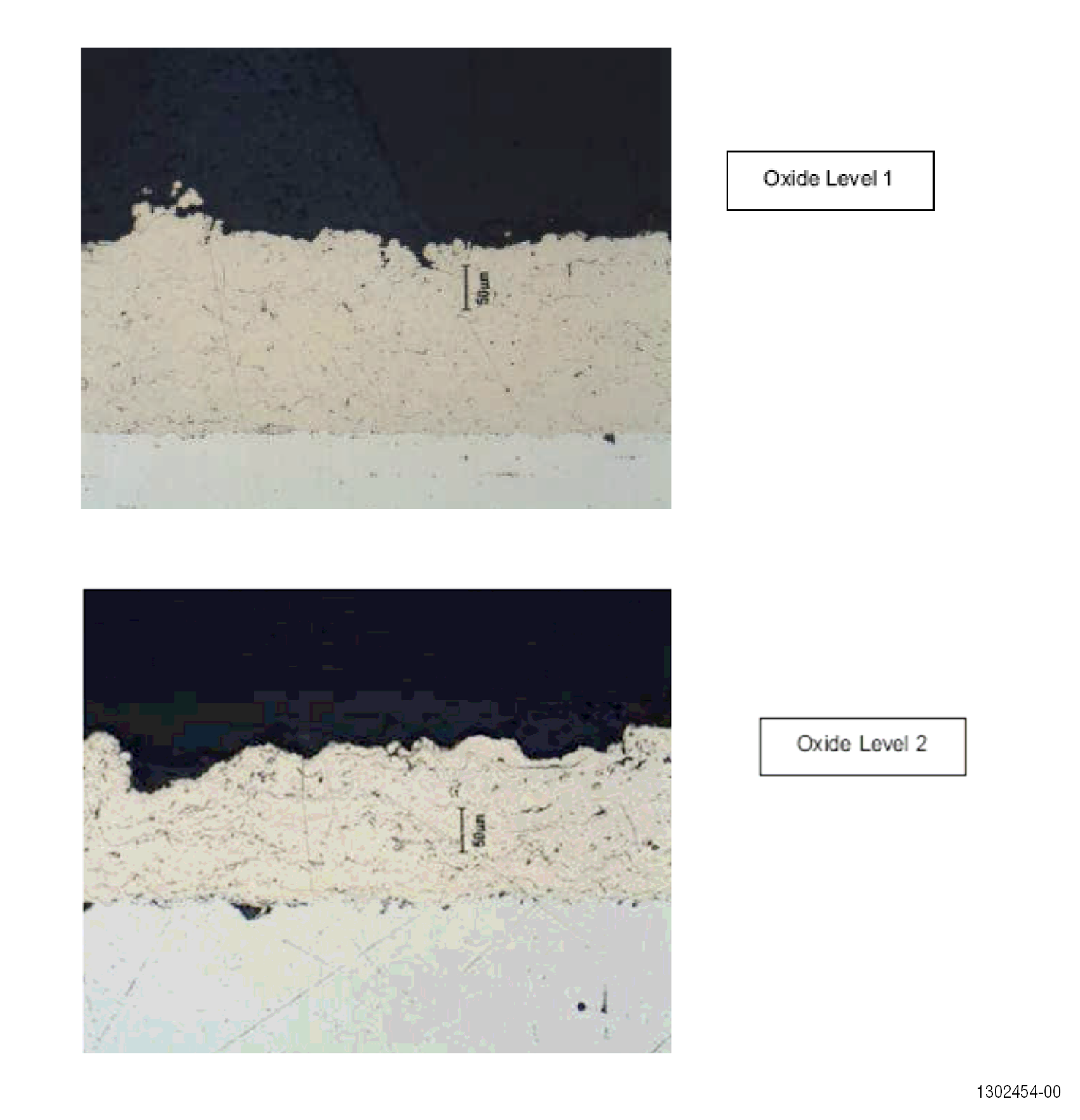
| (d) | Oxides and Oxide Clusters |
| Examine at 200-500X, noting the presence of oxides that may appear in either stringer or globular form. Care must be taken not to include porosity as part of the oxide content. The coating shall be free of oxide clusters as defined in 70-71-04. Oxides shall be uniformly distributed. |
| (e) | Transverse Cracks |
| Examine at 200X. When evaluating for cracks, it is most important to differentiate between cracks caused by mechanical damage and those which are intrinsic to the structure. Cracks that are perpendicular to the base metal may sometimes be caused by flexion of the substrate or by thermal stresses. The later types of cracks are to be noted. The coating must be free of transverse cracks as defined in 70-71-04. |
| (f) | Delaminations |
| Examine at 200X. When evaluating for delaminations, it is most important to differentiate between delaminations caused by mechanical damage and those which are intrinsic to the structure. Delaminations which propagate along or parallel to the base metal interface are commonly (but not always) a result of mechanical damage. The coating shall be free of delaminations as defined in 70-71-04. |
| (g) | Integrity |
| Examine at 200-500X. This is a measure of the overall coating quality and soundness. This characteristic applies to metallurgical abnormalities such as areas of loosely bonded coating, pieces of the gun nozzle in the structure, and other rejectable conditions. The coating shall show acceptable integrity as defined in 70-71-04. |
|
||||||||||||||||||||||||||||||||||||||||||||||||||||||||||||||||||||||||||||||||||||||||||||||||||||||||||||||||||||||||||||||||||||||||||||||||||||||||||||||||||||||||||||||||||||||||||||||||||||||||||||||||||||||||||||||||||||||||||||||||||||||||||||||||||||||||||||||||||||||||||||||||||||||||||||||||||||||||||||||||||||||||||||||||||||||||||||||||||||||||||||||||||