| GENX-1B CLEANING,INSPECTION,AND REPAIR MANUAL | Dated: 03/26/2024 | |
| CIR 72-30-74 , INSPECTION 001 | ||
| VSV TORQUE SHAFT - INSPECTION | ||
| GENX-1B CLEANING,INSPECTION,AND REPAIR MANUAL | Dated: 03/26/2024 | |
| CIR 72-30-74 , INSPECTION 001 | ||
| VSV TORQUE SHAFT - INSPECTION | ||
| * * * FOR ALL |
| TASK 72-30-74-200-801 |
| 1 . | General. |
| A. | This procedure gives instructions to do an inspection of the VSV torque shaft (torque shaft). |
| • |
|
| • |
|
| • |
|
| • |
|
| • |
|
| 2 . | Tools, Equipment, and Materials. |
| NOTE: |
|
| A. | Tools and Equipment. |
| (1) | Special Tools. None. |
| (2) | Standard Tools and Equipment. None. |
| (3) | Locally Manufactured Tools. None. |
| B. | Consumable Materials. None. |
| C. | Referenced Procedures. |
| D. | Expendable Parts. None. |
| 3 . | Specific Inspection Procedure. |
| Subtask 72-30-74-230-001 |
| A. | Alternative Procedure Available. If you think you see cracks, do a Class A fluorescent penetrant inspection to make sure. Refer to TASK 70-32-02-230-001 (FLUORESCENT PENETRANT INSPECTION). |
| Subtask 72-30-74-230-002 |
| A.A. | Alternative Procedure. If you think you see cracks, do a spot-fluorescent-penetrant inspection to make sure. Refer to TASK 70-32-03-230-002 (SPOT-FLUORESCENT-PENETRANT INSPECTION). |
| 4 . | Visual Inspection. |
| Subtask 72-30-74-220-001 |
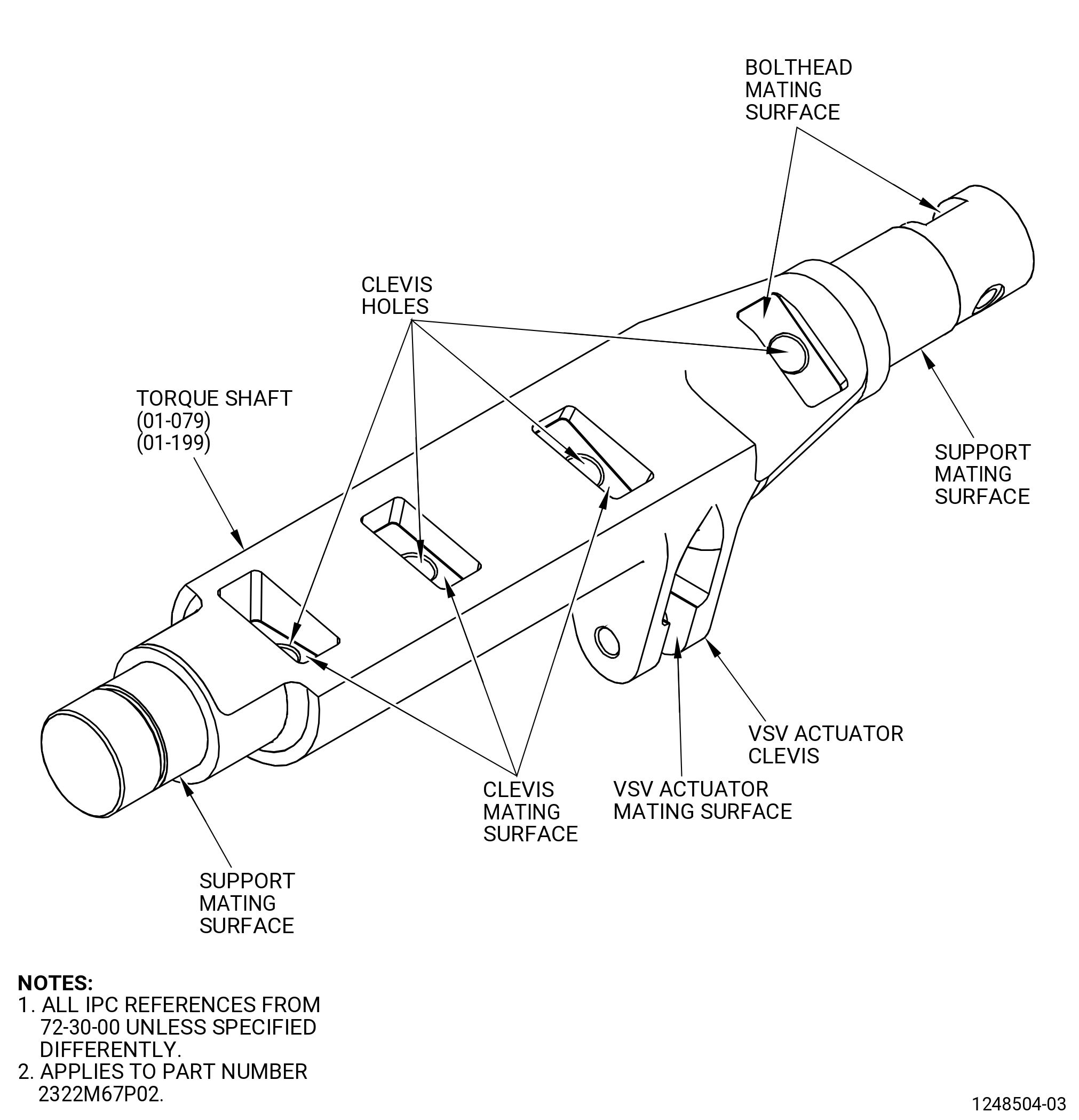
| A. | Do a visual inspection of all surfaces of each torque shaft as follows. Refer to Figure 801. |
| (1) | Cracks: |
| Maximum serviceable limit: |
|
| Repair method: |
|
| Subtask 72-30-74-220-004 |
| (2) | Nicks, dents, and scratches (this does not include the clevis edges) for torque shaft part numbers 2322M67P02, 2363M58P01, and 2363M60P01: |
| Maximum serviceable limit: |
|
| Maximum repairable limit: |
|
| Repair method: |
|
| Subtask 72-30-74-220-005 |
| (3) | Nicks, dents, and scratches on the edges of the VSV actuator clevis and all other edges for torque shaft part numbers 2322M67P02, 2363M58P01, and 2363M60P01: |
| Maximum serviceable limit: |
|
| Maximum repairable limit: |
|
| Repair method: |
|
| Subtask 72-30-74-220-006 |
| (4) | Wear at diameter N for torque shaft part numbers 2322M67P02, 2363M58P01, and 2363M60P01: |
| Maximum serviceable limit: |
|
| Repair method: |
|
| Subtask 72-30-74-220-007 |
| (5) | Fretting on the support mating surfaces for torque shaft part numbers 2322M67P02, 2363M58P01, and 2363M60P01: |
| Maximum serviceable limit: |
|
| Repair method: |
|
| Subtask 72-30-74-220-008 |
| (6) | Local deformation for torque shaft part numbers 2322M67P02, 2363M58P01, and 2363M60P01: |
| Maximum serviceable limit: |
|
| Repair method: |
|
| Subtask 72-30-74-220-018 |
| (7) | Rub marks on the VSV actuator clevis for torque shaft part numbers 2322M67P02, 2363M58P01, and 2363M60P01: |
| Maximum serviceable limit: |
|
| Repair method: |
|
| Subtask 72-30-74-220-020 |
| (8) | Rub marks, wear and galling on the VSV actuator mating surfaces for torque shaft part numbers 2322M67P02, 2363M58P01, and 2363M60P01: |
| Maximum serviceable limit: |
|
| Repair method: |
|
| Subtask 72-30-74-220-021 |
| * * * DELETED( ) |
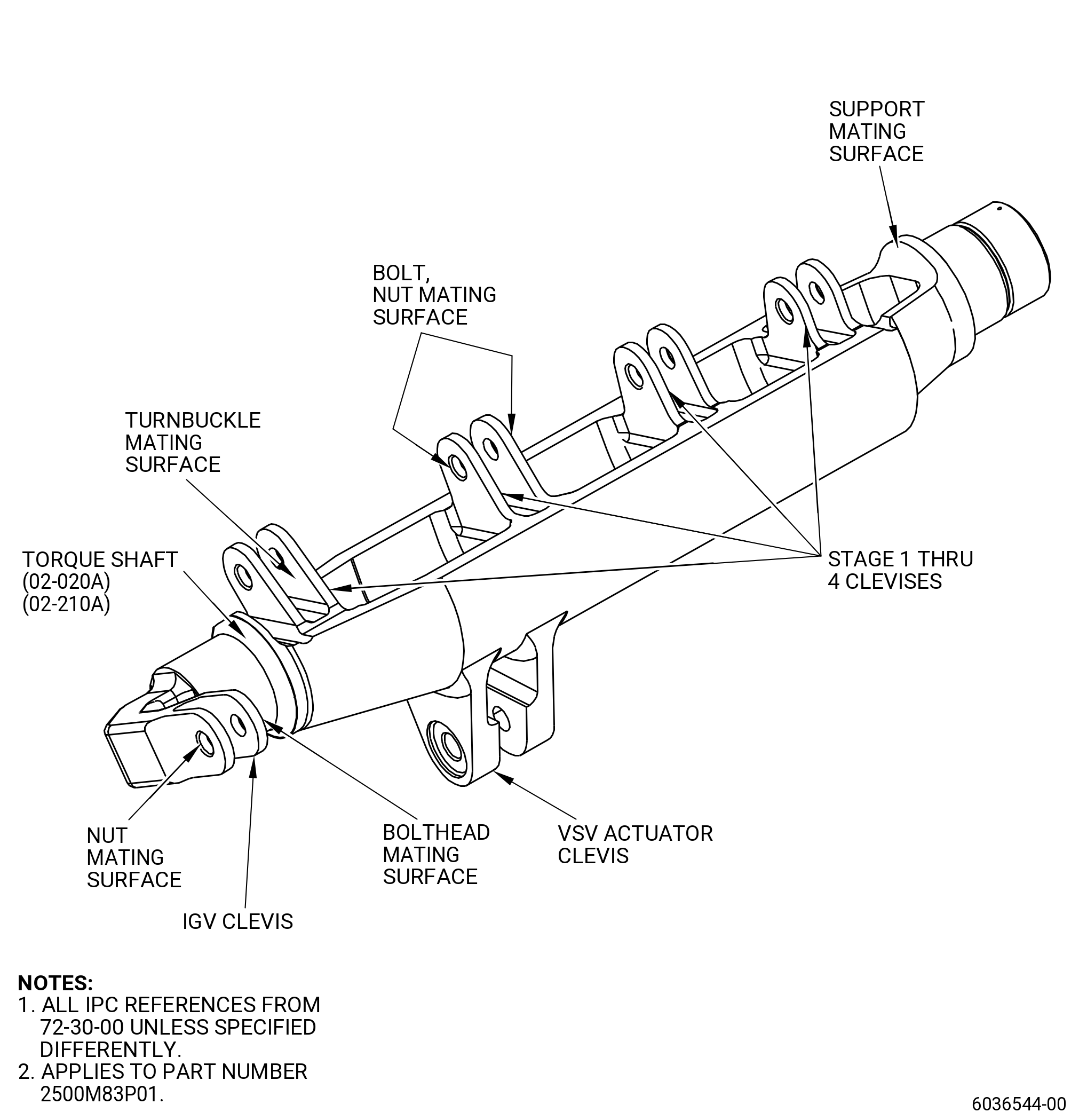
| B. | Do an inspection of the IGV clevis and stage 1 thru stage 4 clevises. Refer to Figure 801A. |
| NOTE: |
|
| (1) | Nicks, dents, and scratches on each clevis for torque shaft part number 2363M58P01: |
| Maximum serviceable limit: |
|
| Maximum repairable limit: |
|
| Repair method: |
|
| Subtask 72-30-74-220-023 |
| (2) | Rub marks on the bolthead, turnbuckle, and nut mating surface for torque shaft part number 2363M58P01: |
| Maximum serviceable limit: |
|
| Repair method: |
|
| * * * DELETED |
| Subtask 72-30-74-220-024 |
| * * * DELETED( ) |
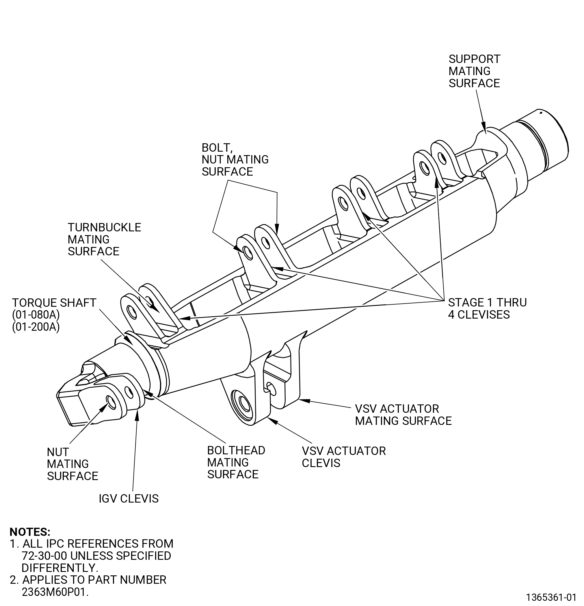
| B.A. | Do an inspection of the IGV clevis and stage 1 thru stage 4 clevises. Refer to Figure 801B. |
| NOTE: |
|
| (1) | Nicks, dents, and scratches on each clevis for torque shaft part number 2363M60P01: |
| Maximum serviceable limit: |
|
| Maximum repairable limit: |
|
| Repair method: |
|
| Subtask 72-30-74-220-025 |
| (2) | Rub marks on the bolthead, turnbuckle, and nut mating surface for torque shaft part number 2363M60P01: |
| Maximum serviceable limit: |
|
| Repair method: |
|
| * * * DELETED |
| Subtask 72-30-74-220-002 |
| * * * DELETED( ) |
| C. | Do a visual inspection of the clevis holes of the torque shaft as follows. Refer to Figure 801. |
| NOTE: |
|
| (1) | Nicks, dents, scratches, and pits on the ID for torque shaft part number 2322M67P02: |
| Maximum serviceable limit: |
|
| Maximum repairable limit: |
|
| Repair method: |
|
| Subtask 72-30-74-220-009 |
| (2) | Wear or grooves around the clevis holes of the torque shaft in the ID for torque shaft part number 2322M67P02: |
| Maximum serviceable limit: |
|
| Maximum repairable limit: |
|
| Repair method: |
|
| * * * DELETED |
| Subtask 72-30-74-220-027 |
| D. | Do an inspection of the actuator clevis, IGV clevis, and stage 1 through stage 4 clevises for integral clevis or casting configuration. Refer to Figure 803. |
| NOTE: |
|
| (1) | Wear due to contact with turnbuckle rod end on inner surface of the shaft stage clevises (IGV through stage 4) for torque shaft part number 2500M83P01: |
| Maximum serviceable limit: |
|
| Repair method: |
|
| Subtask 72-30-74-220-032 |
| (2) | Wear due to contact with actuator rod end on inner surface of the shaft actuator clevis for torque shaft part number 2500M83P01 without bushings installed in the actuator clevis: |
| Maximum serviceable limit: |
|
| Repair method: |
|
| Subtask 72-30-74-220-033 |
| (3) | Wear caused due to contact with the actuator rod end on the bushing for torque shaft part number 2500M83P01 with the bushings in the actuator clevis: |
| Maximum serviceable limit: |
|
| Repair method: |
|
| Subtask 72-30-74-220-028 |
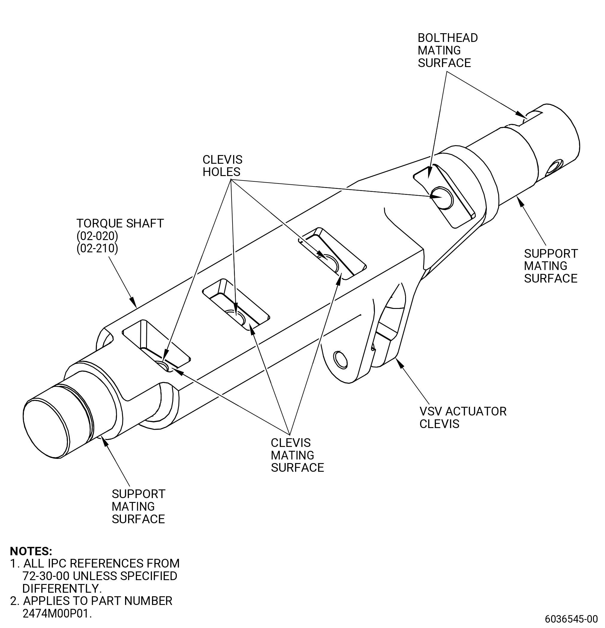
| E. | Do an inspection of the actuator clevis for separable clevis or bolted-on configuration. Refer to Figure 804. |
| (1) | Wear due to contact with actuator rod end on inner surface of the shaft actuator clevis for torque shaft part number 2474M00P01: |
| Maximum serviceable limit: |
|
| Repair method: |
|
| 5 . | Special Dimensional Inspection. |
| Subtask 72-30-74-220-026 |
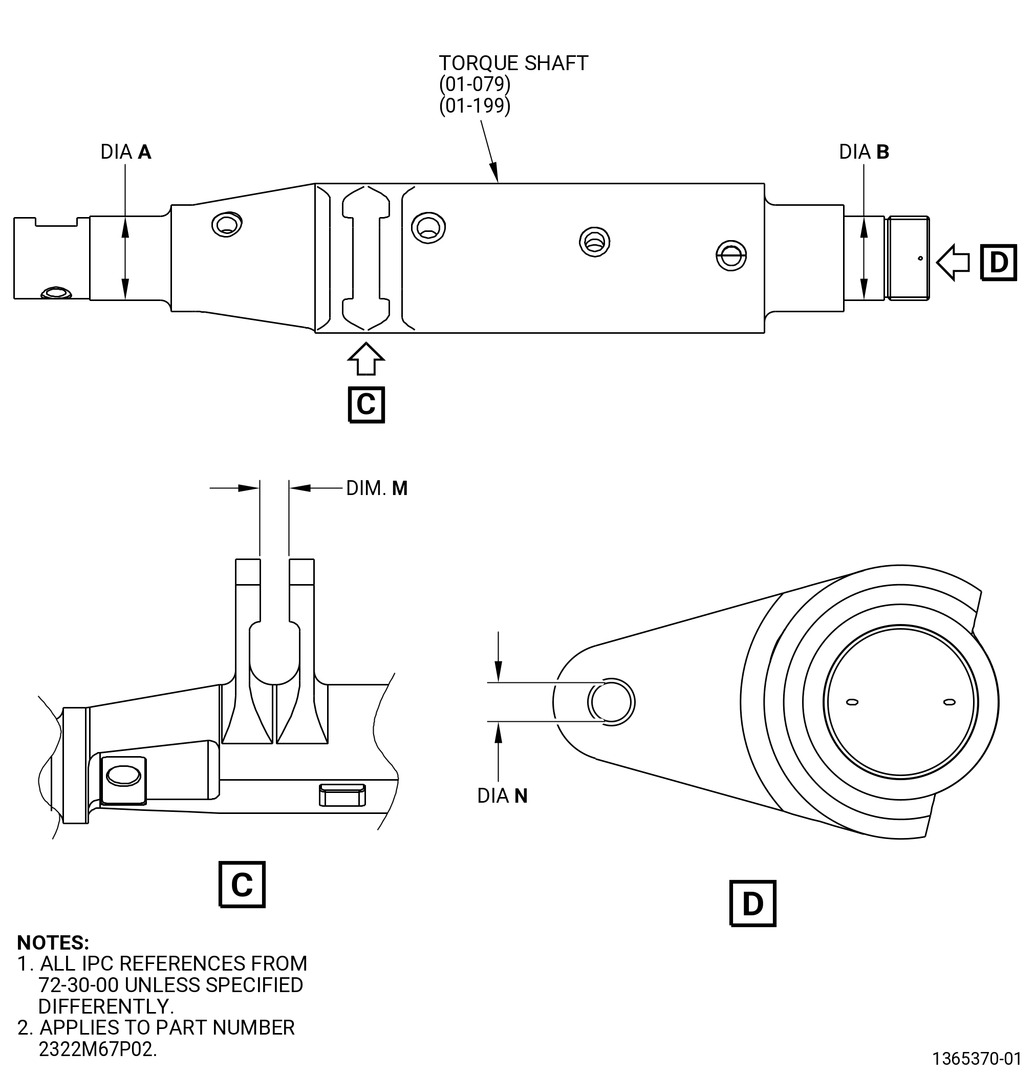
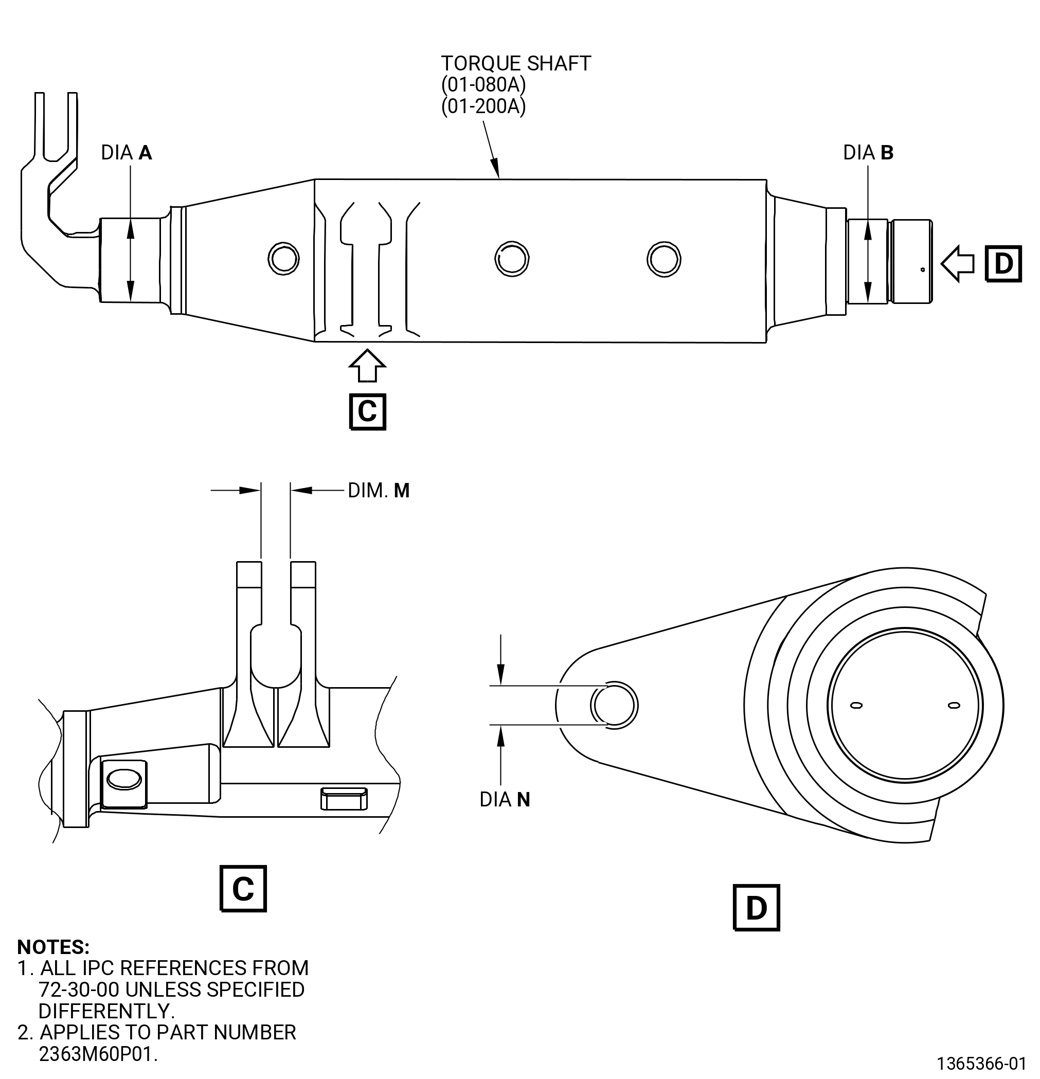
| A. | Do this special dimensional inspection only if a visual inspection shows any defect or other conditions that make a dimensional inspection necessary. For torque shaft part numbers 2322M67P02, 2363M58P01, and 2363M60P01. Refer to Figure 802, Figure 802A, and Figure 802B. |
| Subtask 72-30-74-220-003 |
| B. | Do a dimensional inspection of each torque shaft as follows. Refer to Figure 802, Figure 802A, and Figure 802B. |
| (1) | Diameter A: |
| Minimum serviceable limit: |
|
| Maximum serviceable limit: |
|
| Repair method: |
|
| Subtask 72-30-74-220-010 |
| (2) | Diameter B: |
| Minimum serviceable limit: |
|
| Maximum serviceable limit: |
|
| Repair method: |
|
| Subtask 72-30-74-220-013 |
| (3) | Dimension M: |
| Minimum serviceable limit: |
|
| Maximum serviceable limit: |
|
| Repair method: |
|
| Subtask 72-30-74-220-017 |
| (4) | Diameter N: |
| Minimum serviceable limit: |
|
| Maximum serviceable limit: |
|
| Repair method: |
|