| GENX-1B CLEANING,INSPECTION,AND REPAIR MANUAL | Dated: 03/26/2024 | |
| CIR 72-30-74 , REPAIR 001 | ||
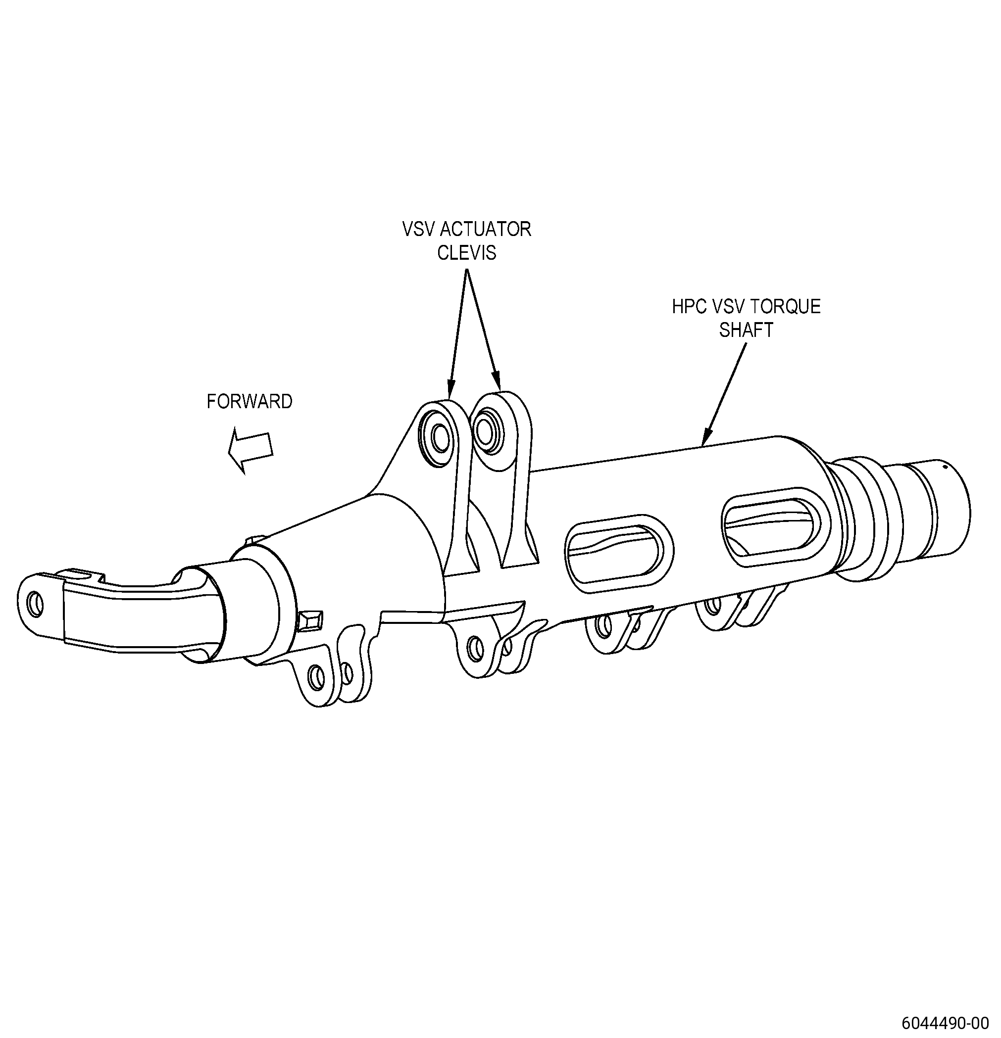
| VARIABLE STATOR VANE TORQUE SHAFT - REPAIR - BUSHING REPAIR ON THE ACTUATOR CLEVIS | ||
| GENX-1B CLEANING,INSPECTION,AND REPAIR MANUAL | Dated: 03/26/2024 | |
| CIR 72-30-74 , REPAIR 001 | ||
| VARIABLE STATOR VANE TORQUE SHAFT - REPAIR - BUSHING REPAIR ON THE ACTUATOR CLEVIS | ||
| * * * FOR ALL |
| TASK 72-30-74-300-801 |
| 1 . | Bushing Repair on the Actuator Clevis. |
| A. | This procedure gives instructions to repair the variable stator vane (VSV) torque shaft by machining the actuator clevis to remove wear and installing new bushings. Refer to Figure 901. |
| B. | The following maximum repairable limits apply to this repair: |
| NOTE: |
|
| (4) | Visual Inspection. |
| (d) | Do an inspection of the actuator clevis, IGV clevis, and stage 1 through stage 4 clevises for integral clevis or casting configuration. Refer to Figure 803. |
| 2 | Wear due to contact with actuator rod end on inner surface of the shaft actuator clevis for torque shaft part number 2500M83P01 without bushings installed in the actuator clevis. |
| Maximum repairable limit: |
|
| 3 | Wear due to contact with actuator rod end on the bushings for torque shaft part number 2500M83P01 with bushings installed in the actuator clevis. |
| Maximum repairable limit: |
|
| C. | The subsequent table gives a list of the part numbers that are applicable to this procedure. All part numbers are applicable to all paragraphs unless specified differently. |
|
|||||||||||||||||||||||
| D. | Proprietary/Complex Process Statement. |
| (1) | None. |
| 2 . | Tools, Equipment, and Materials. |
| NOTE: |
|
| A. | Tools and Equipment. |
| (1) | Special Tools. None. |
| (2) | Standard Tools and Equipment. None. |
| (3) | Locally Manufactured Tools. |
|
| B. | Consumable Materials. |
|
| C. | Referenced Procedures. |
| D. | Expendable Parts. None. |
| E. | SPD Information. |
| (1) | Spares Supplied. None. |
| (2) | Protected Spares. None. |
| (3) | Locally Manufactured Spares. |
|
| F. | Special Solutions. None. |
| G. | Test Specimens. None. |
| 3 . | Dimensional Information. |
| Subtask 72-30-74-220-029 |
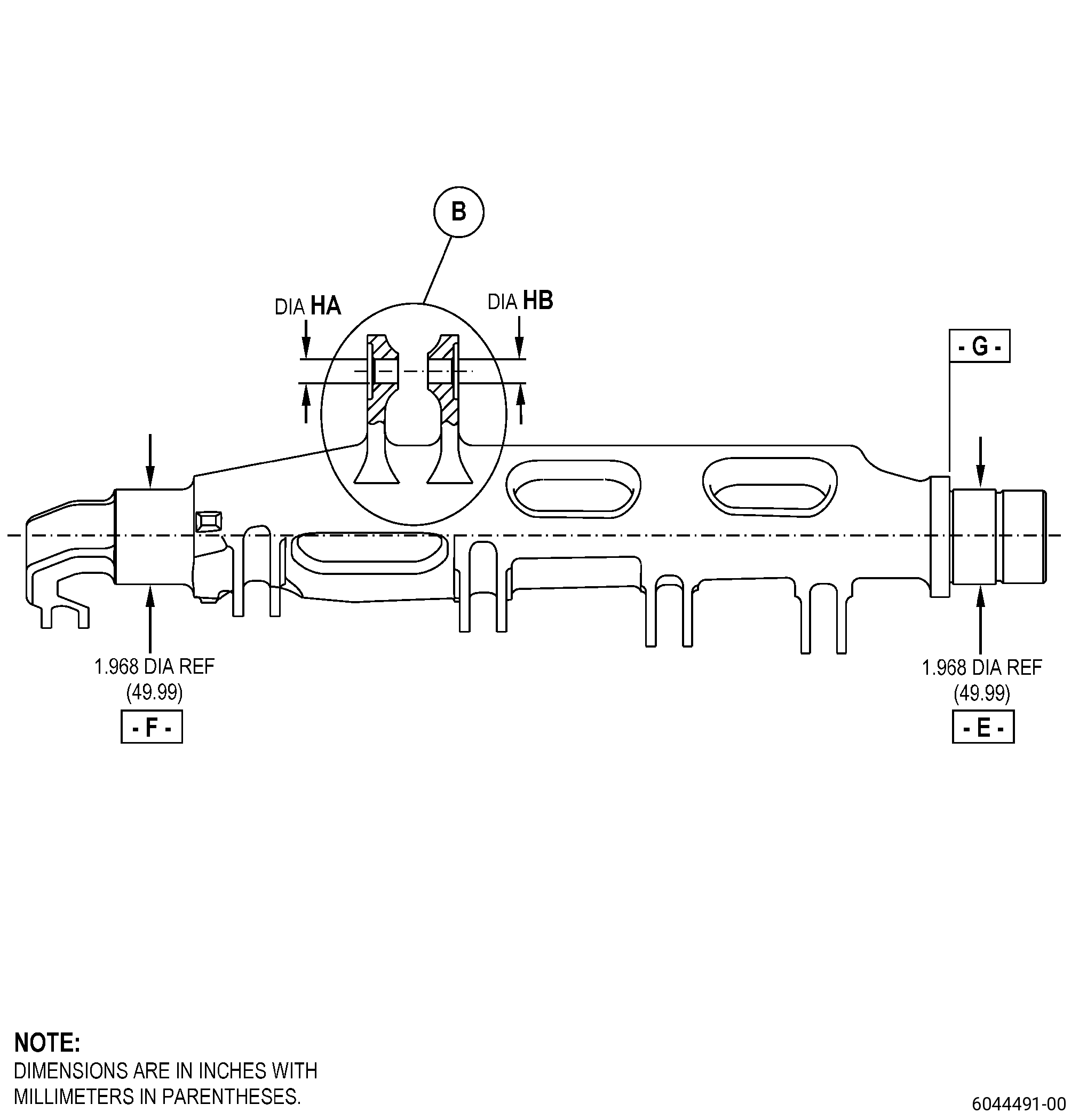
| A. | Refer to Figure 901, Figure 902, and Figure 903 for specified dimensions and locations. |
| NOTE: |
|
| NOTE: |
|
| 4 . | Setup Information. |
| Subtask 72-30-74-350-001 |
| A. | Set-up the torque shaft on a machining table to machine the clevis or the bushings if necessary. Refer to Figure 901, Figure 902, and as follows: |
| CAUTION: |
|
| (1) | Put diameter E and diameter F onto ground V-blocks or equivalent. |
| (2) | Hold the torque shaft with machining clamps. |
| (3) | Make sure that the centerline of the shaft is parallel to the machine spindle axis. The runout must be 0.001 inch (0.03 mm) maximum or better, then do as follows: |
| (a) | Use diameter E and diameter F to find the shaft centerline. If necessary add shims to find parallelism. |
| (4) | Diameter HA must have a runout that is 0.0005 inch (0.013 mm) maximum or better to the machine spindle. |
| (5) | Surface D must be perpendicular to diameter HA and must have a runout that is 0.0005 inch (0.013 mm) maximum or better. |
| (6) | Diameter HA must be concentric to diameter HB and must have a runout that is 0.0005 inch (0.013 mm) maximum or better. |
| 5 . | Procedure. |
| Subtask 72-30-74-160-003 |
| A. | Clean the repair area of the torque shaft. Refer to TASK 72-30-74-100-801 (72-30-74, CLEANING 001). |
| Subtask 72-30-74-320-001 |
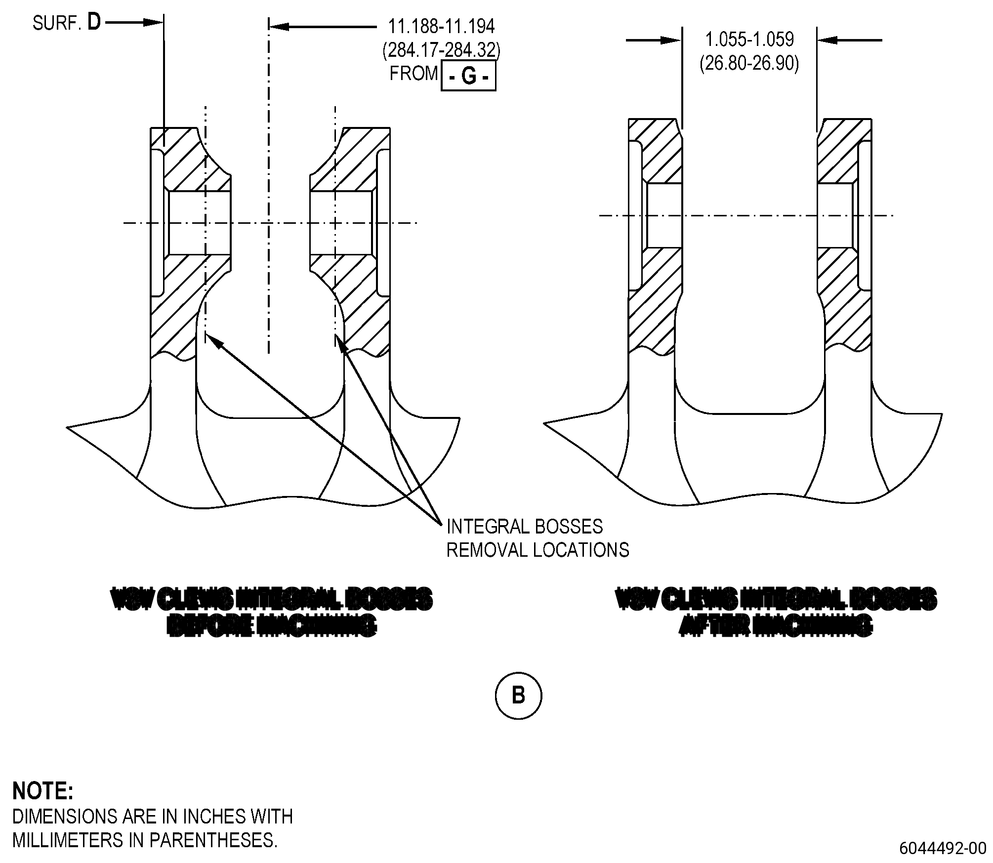
| B. | If the clevis has not been previously repaired with this procedure, machine the integral bosses and clevis counterbores. Refer to TASK 70-00-03-800-004 (MACHINING DATA), Figure 901, Figure 902, and as follows: |
| (1) | Set-up the torque shaft to machine the clevis. Refer to Subtask 72-30-74-350-001 (paragraph 4.A.). |
| (2) | Machine the integral bosses. |
| (3) | Machine the clevis counterbores. |
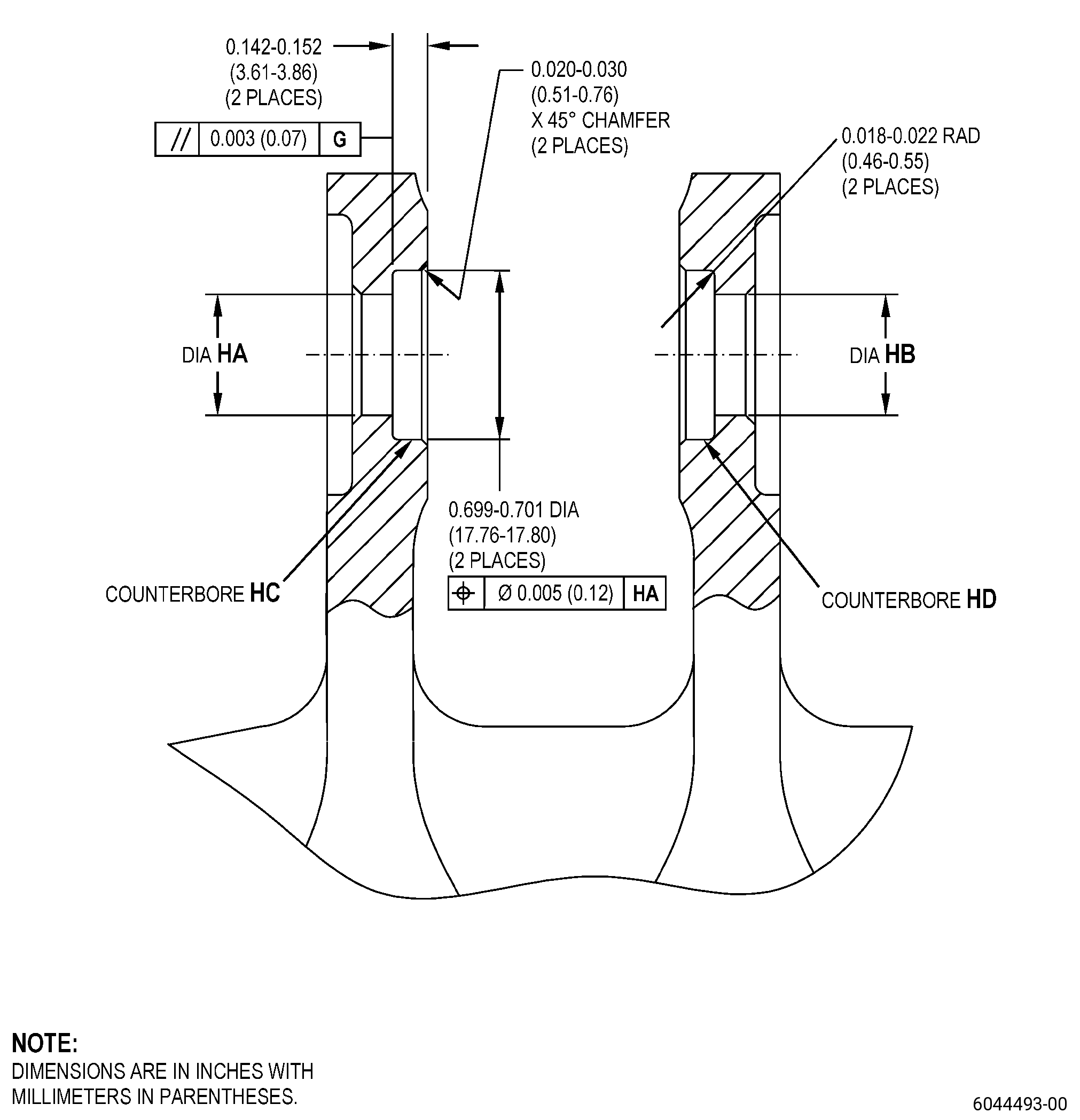
| (4) | Measure and record the machined diameter and depth of clevis counterbore HC and clevis counterbore HD. |
| Subtask 72-30-74-350-002 |
| C. | If the clevis bosses have bushings installed, remove the bushings. Refer to Figure 901, Figure 902, and as follows: |
| (1) | Set-up the torque shaft on a machining table to machine the bushings. Refer to Subtask 72-30-74-350-001 (paragraph 4.A.). |
| CAUTION: |
|
| (2) | Machine the bushing inner diameters (IDs) as follows: |
| (a) | Machine the IDs to a diameter less than the bushing outer diameters (ODs) to decrease the bushing wall thickness. |
| (b) | Do not machine surface HC or surface HD of the clevis counterbore during the removal of the bushing material. |
| CAUTION: |
|
| (3) | Use a punch to carefully remove the remaining bushing material from the counterbore. |
| (4) | Measure and record the machined diameter of each clevis counterbore and the depth of each counterbore from the machined clevis surfaces. |
| Subtask 72-30-74-350-003 |
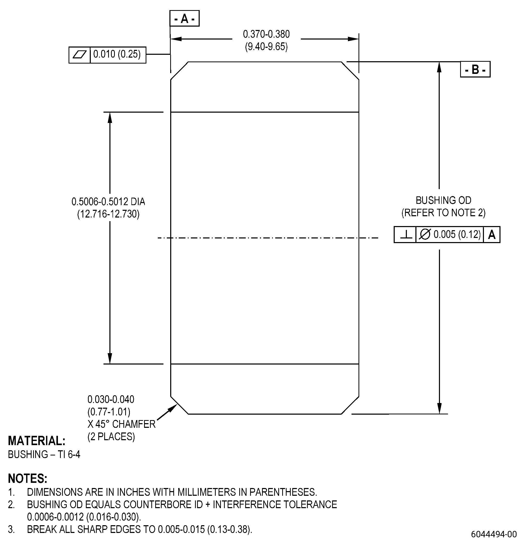
| D. | Make the new bushings. Refer to TASK 70-00-03-800-004 (MACHINING DATA), Figure 903, and as follows: |
| (1) | Each bushing OD must have a diametric interference fit of 0.0006-0.0012 inch (0.016-0.030 mm) with the related machined counterbore where it will be installed. |
| (2) | Measure and record the bushings OD and full length. |
| Subtask 72-30-74-350-004 |
| E. | Etch the machined areas of the torque shaft. Refer to TASK 70-24-00-110-033 (ETCHING PROCEDURES FOR FLUORESCENT-PENETRANT INSPECTION), TASK 70-24-01-110-034 (SWAB ETCHING PROCEDURE), and as follows: |
| (1) | Use Class B etchant. |
| Subtask 72-30-74-230-003 |
| F. | Do an inspection of the machined counterbores and bushings. Refer to TASK 70-32-00-200-002 (INDIRECT INSPECTION METHODS), TASK 70-32-03-230-002 (SPOT-FLUORESCENT-PENETRANT INSPECTION), and as follows: |
| (1) | Use Class D penetrant. |
| (2) | Refer to TASK 70-31-02-220-003 (ACCEPTABILITY LIMITS FOR FLUORESCENT PENETRANT INSPECTION), and as follows: |
| (a) | Use Class A limits. |
| Subtask 72-30-74-160-004 |
| G. | Clean the torque shaft repair areas and the bushings. Refer to TASK 72-30-74-100-801 (72-30-74, CLEANING 001). |
| Subtask 72-30-74-350-005 |
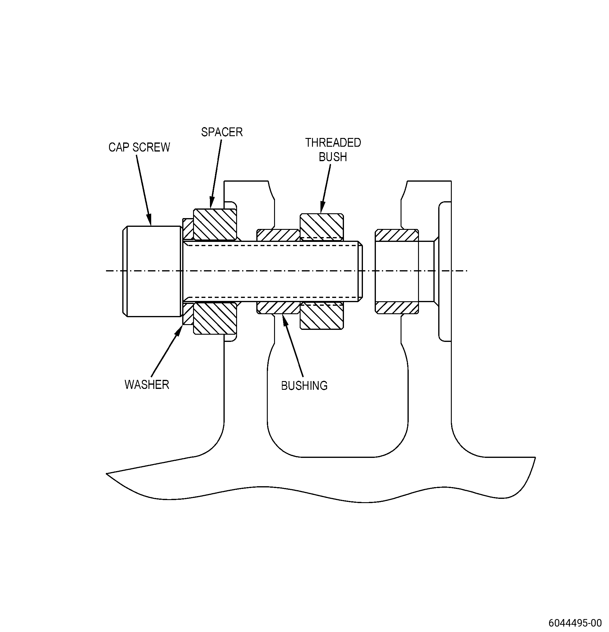
| H. | Install the bushings into the torque shaft machined counterbores. Refer to TASK 70-10-00-800-009 (ASSEMBLY AND DISASSEMBLY TECHNIQUES), and as follows: |
| (1) | For bushing installation, use assembly procedure for interference-fit parts. |
| WARNING: |
|
| WARNING: |
|
| WARNING: |
|
| (2) | Chill the bushings with dry-ice or liquid nitrogen to help with the installation. |
| (3) | Select the new bushing for the related counterbore to get the correct interference fit. |
| (4) | Make the bushing installation tool to install the bushings into the torque shaft. Refer to Figure 904. |
| (5) | Make sure that the bushings are fully installed in the counterbores as follows: |
| (a) | Measure the distance from the bushing outer surface to the machined clevis surface, and as follows: |
| 1 | Add the recorded depth of the counterbore. The sum of these two values must be equal to the recorded overall bushing length when made. |
| (b) | If the sum is not equal to the overall bushing length remove the bushing and do Subtask 72-30-74-350-005 (paragraph 5.H.(1)) thru Subtask 72-30-74-350-005 (paragraph 5.H.(4)) again. |
| Subtask 72-30-74-320-002 |
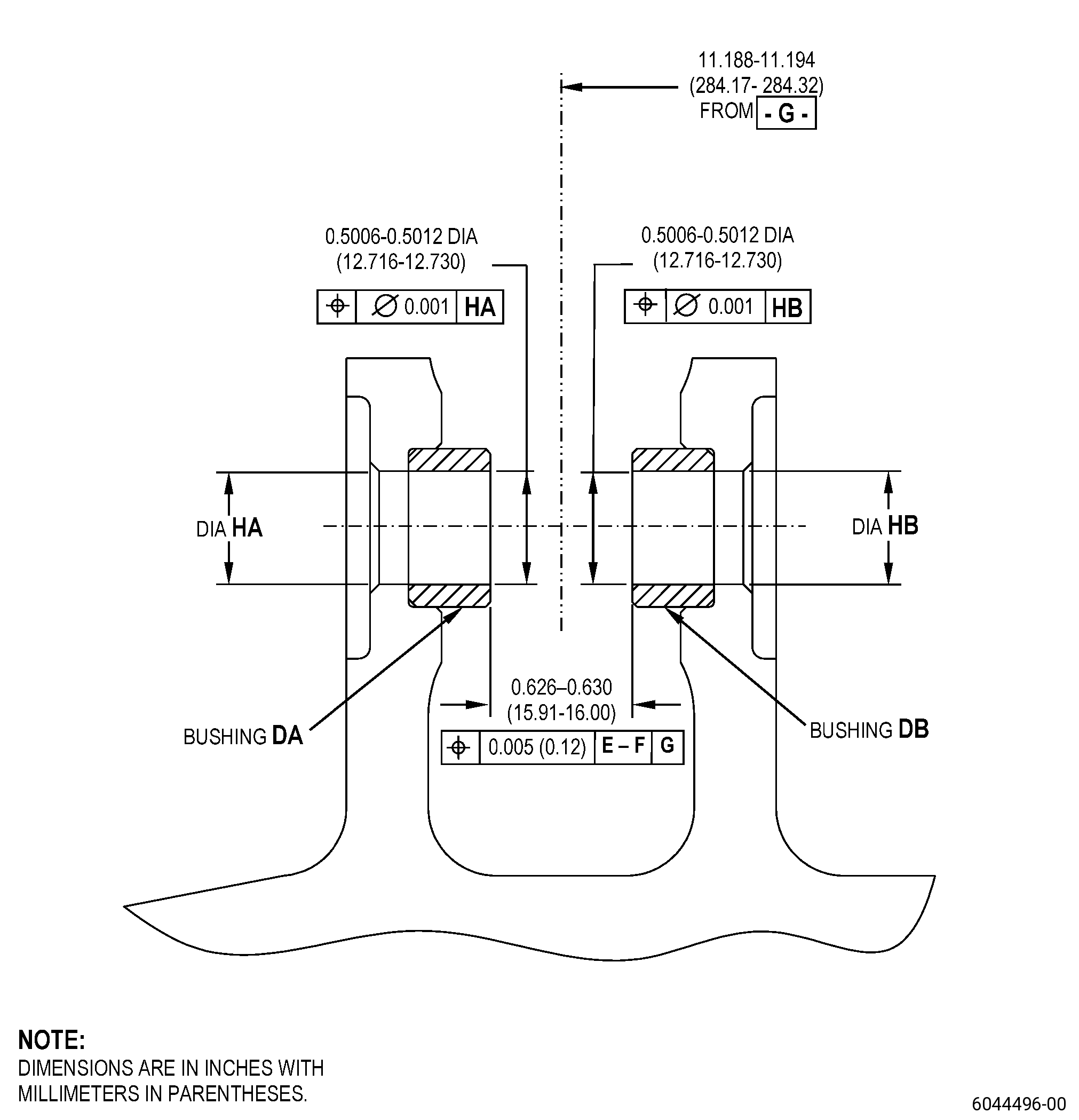
| I. | Machine the protruding surface of the bushings to get the final dimensions for the clevis width. Refer to TASK 70-00-03-800-004 (MACHINING DATA), Figure 905, and as follows: |
| (1) | Do a dimensional inspection of the final machined distance between the two bushings in the clevis. |
| Subtask 72-30-74-220-030 |
| J. | Do a dimensional inspection of the bushing IDs. Refer to Figure 905 and as follows: |
| (1) | Measure the IDs of the bushings. |
| (2) | Measure the concentricity and true position of the bushing IDs. |
| (3) | If the IDs of the bushings do not agree with the limits, do the repair again. |
| Subtask 72-30-74-350-006 |
| K. | Etch the bushing machined surface. Refer to TASK 70-24-00-110-033 (ETCHING PROCEDURES FOR FLUORESCENT-PENETRANT INSPECTION) , TASK 70-24-01-110-034 (SWAB ETCHING PROCEDURE) , and as follows: |
| (1) | Use Class B etchant. |
| Subtask 72-30-74-220-031 |
| L. | Do an inspection of the bushing machined surface. Refer to TASK 70-32-00-200-002 (INDIRECT INSPECTION METHODS), TASK 70-32-03-230-002 (SPOT-FLUORESCENT-PENETRANT INSPECTION), and as follows: |
| (1) | Use Class D penetrant. |
| (2) | Refer to TASK 70-31-02-220-003 (ACCEPTABILITY LIMITS FOR FLUORESCENT PENETRANT INSPECTION), and as follows: |
| (a) | Use Class A limits. |
| Subtask 72-30-74-160-005 |
| M. | Clean the torque shaft. Refer to TASK 72-30-74-100-801 (72-30-74, CLEANING 001). |