| GENX-1B ENGINE MANUAL | Dated: 06/27/2023 | |
| EM 72-00-01 , SPECIAL PROCEDURES 003 | ||
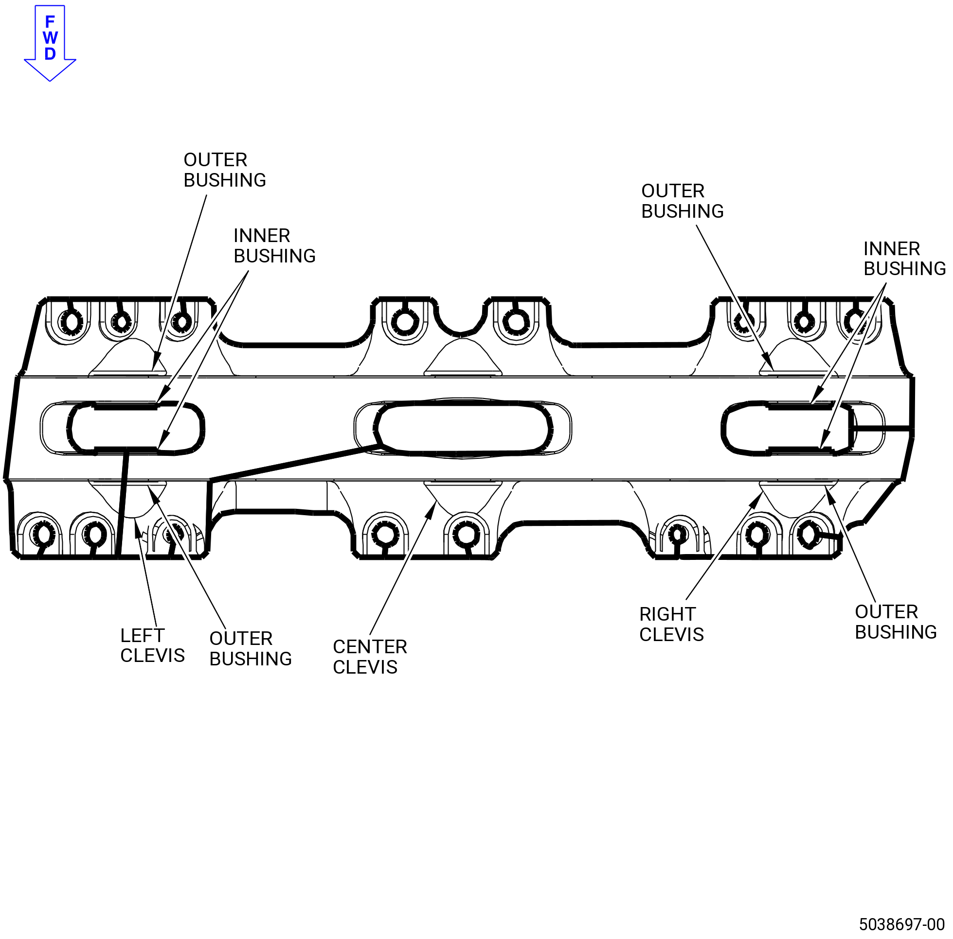
| FAN STATOR MODULE ASSEMBLY - SPECIAL PROCEDURE 003 - FORWARD ENGINE MOUNT YOKE BUSHING REMOVAL AND INSTALLATION | ||
| GENX-1B ENGINE MANUAL | Dated: 06/27/2023 | |
| EM 72-00-01 , SPECIAL PROCEDURES 003 | ||
| FAN STATOR MODULE ASSEMBLY - SPECIAL PROCEDURE 003 - FORWARD ENGINE MOUNT YOKE BUSHING REMOVAL AND INSTALLATION | ||
| * * * FOR ALL |
| TASK 72-00-01-800-803 |
| 1 . | Forward Engine Mount Yoke Bushing Removal and Installation. |
| A. | This procedure provides instructions for removal and installation of the forward engine mount yoke (05-010 , 72-21-00) (SIN 84803) bushings. Refer to Figure 210. |
| B. | All the removed bushings must be replaced with the new bushings. |
| C. | This procedure can be applied to multiple forward engine mount yoke bushings on the same mount yoke. |
| D. | This procedure can be performed with the forward engine mount yoke removed. |
| 2 . | Tools, Equipment, and Materials. |
| A. | Tools and Equipment. |
| (1) | Special Tools. None. |
| (2) | Standard Tools and Equipment. None. |
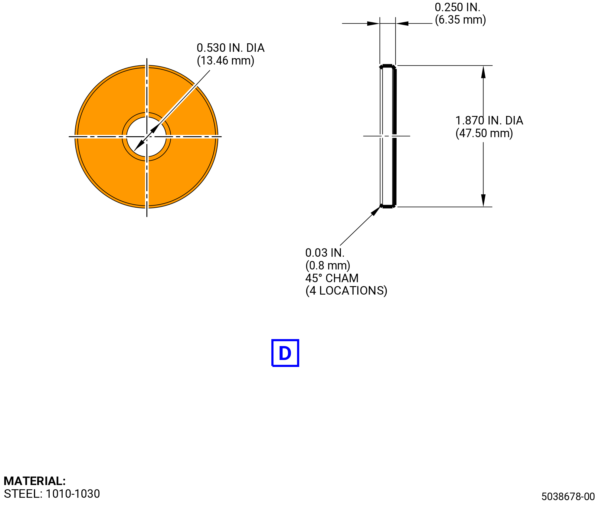
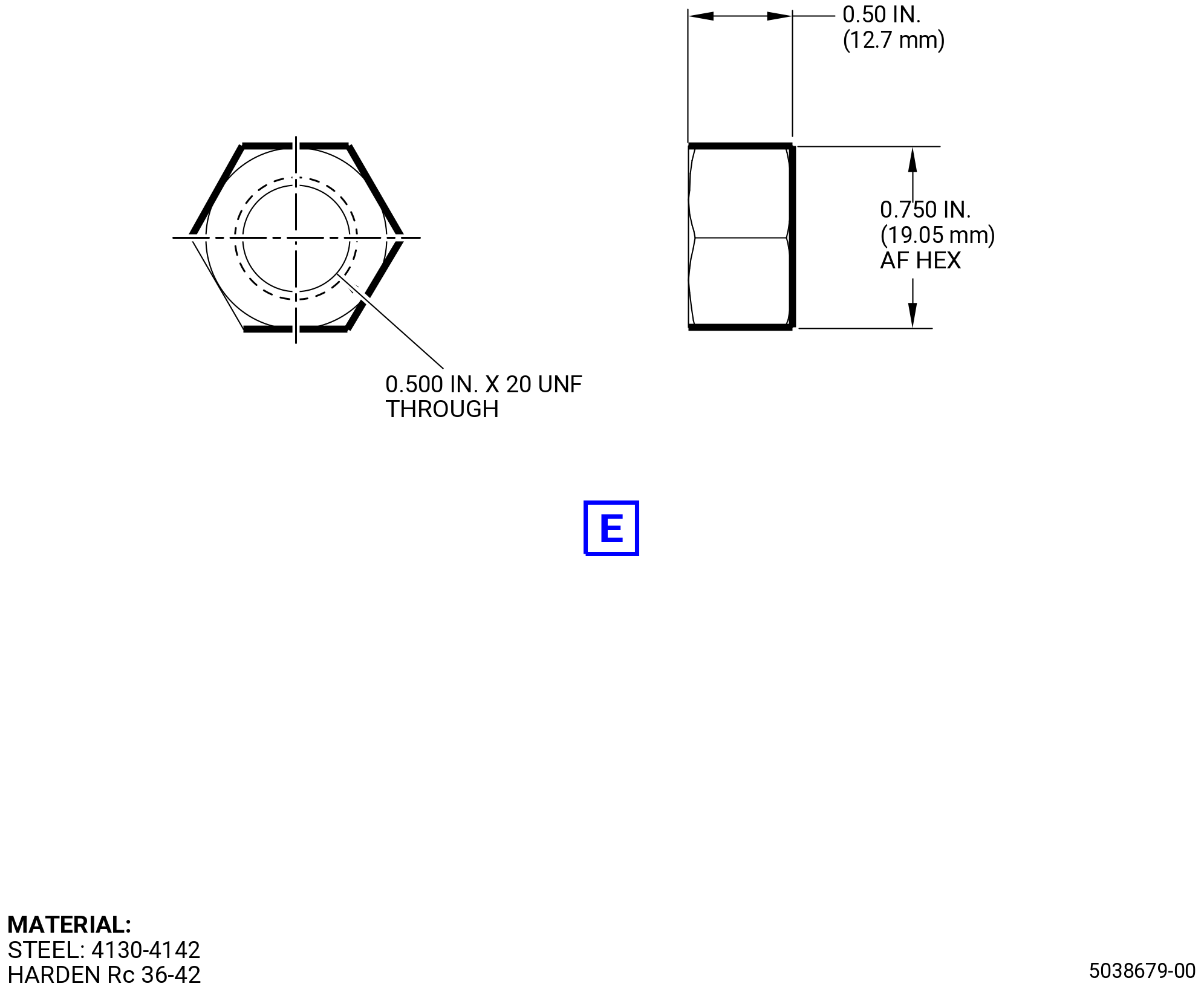
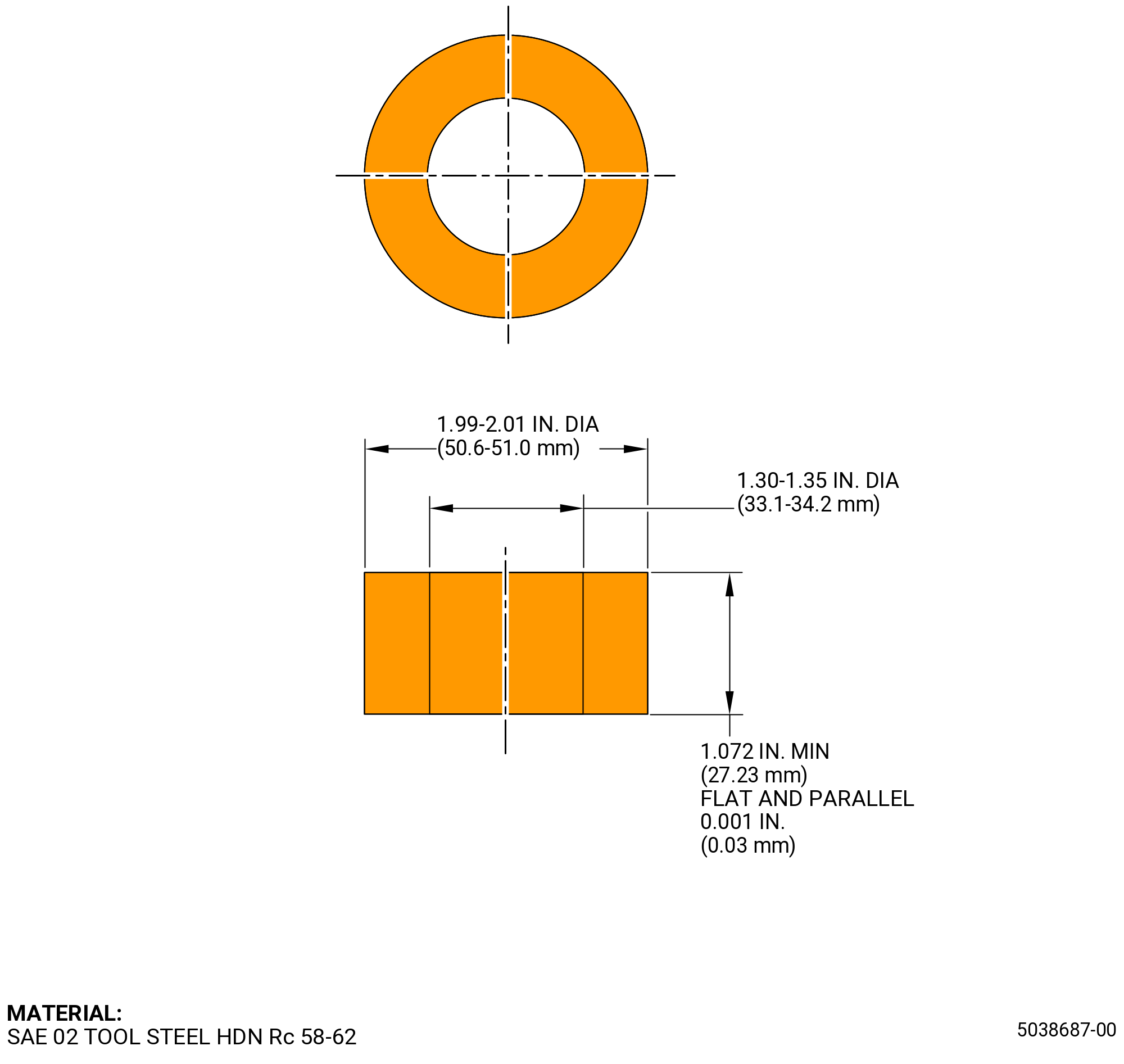
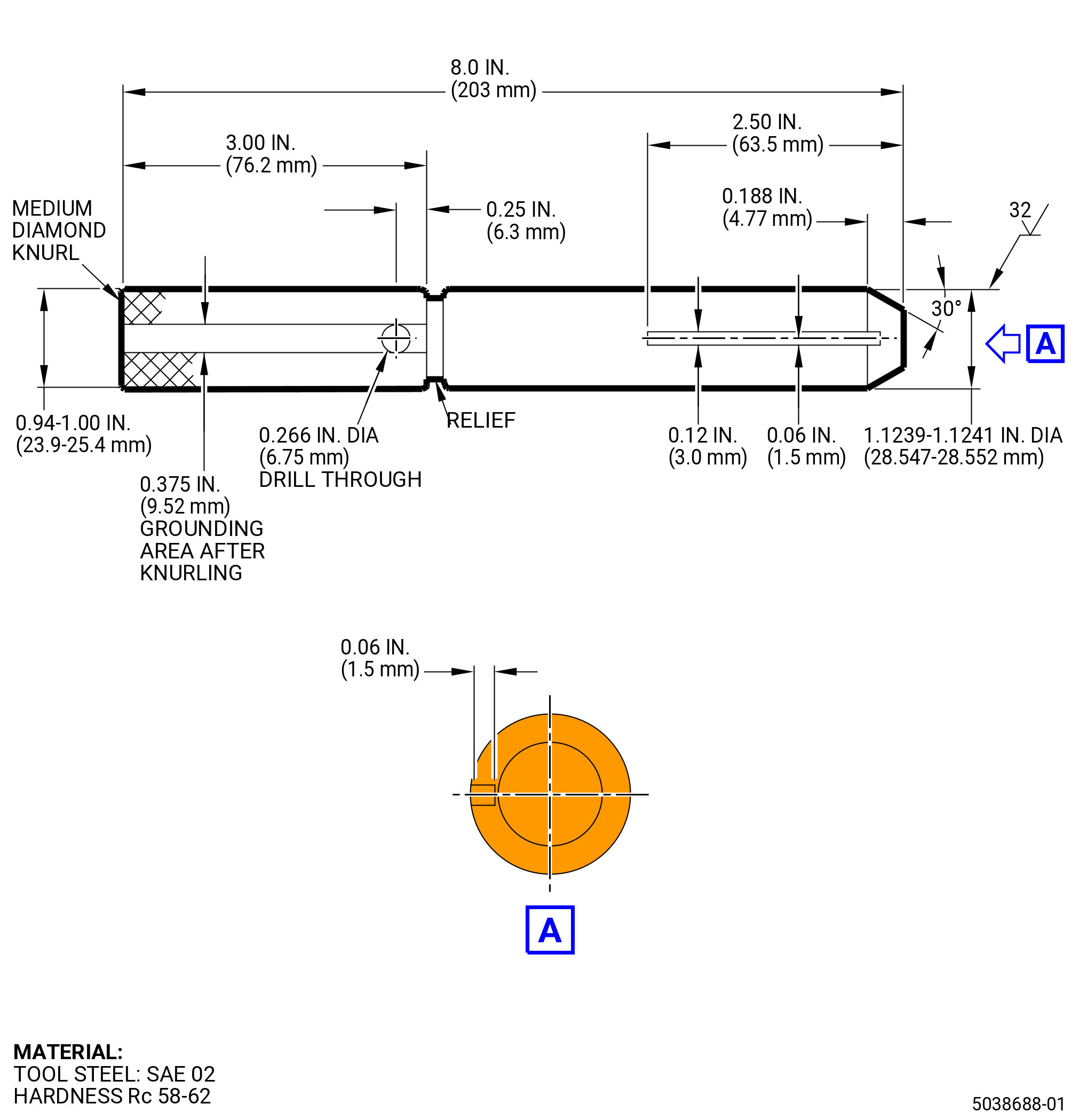
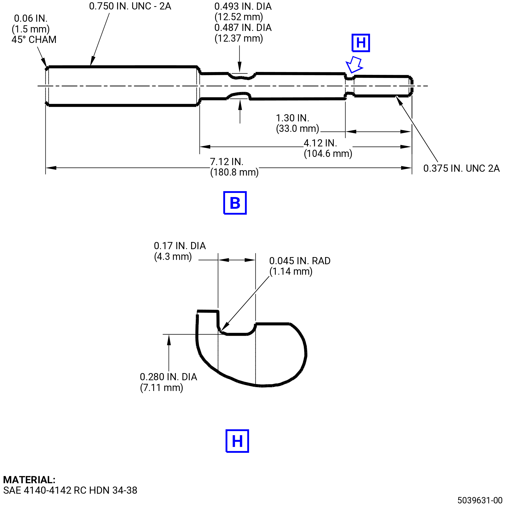
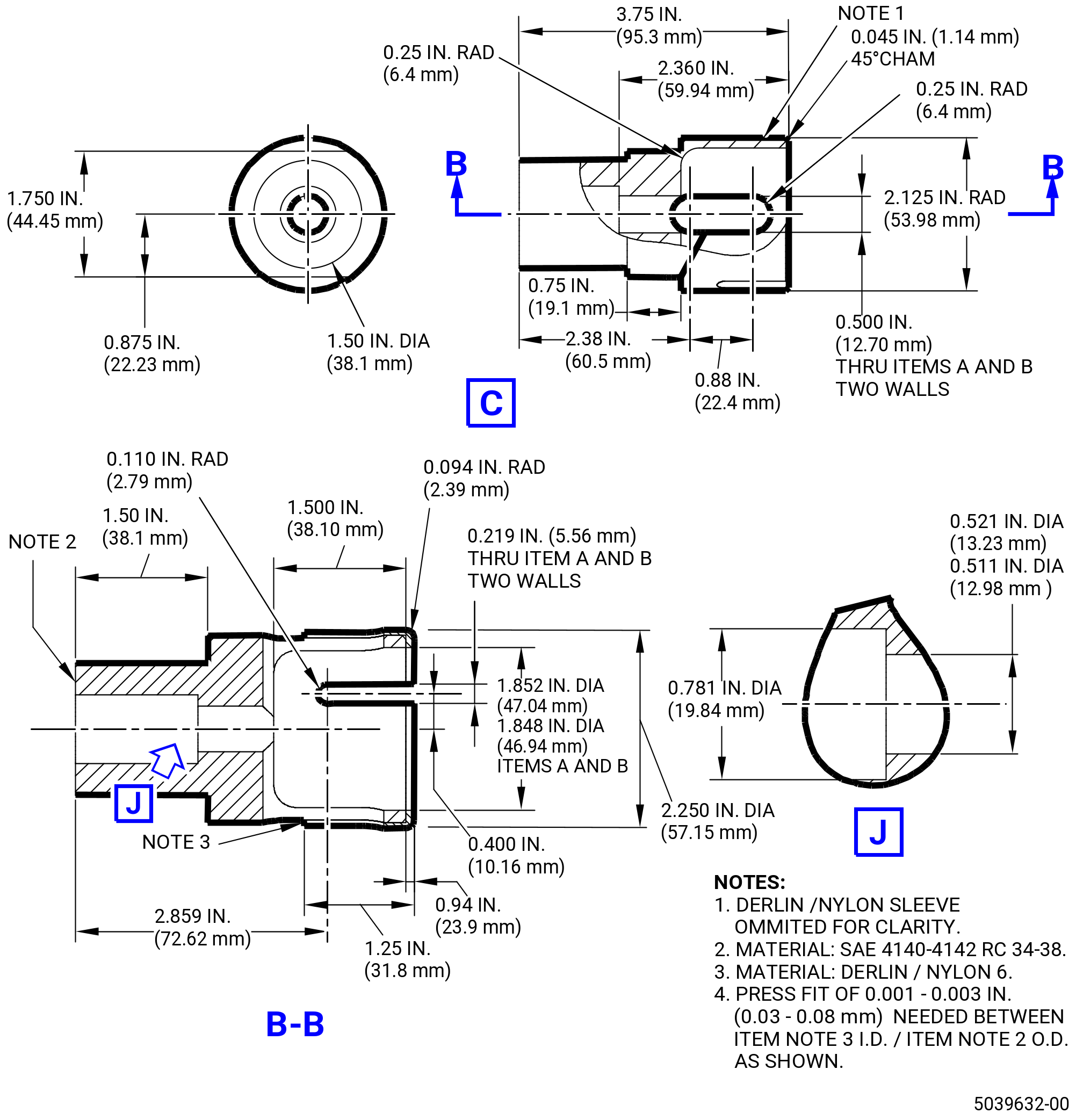
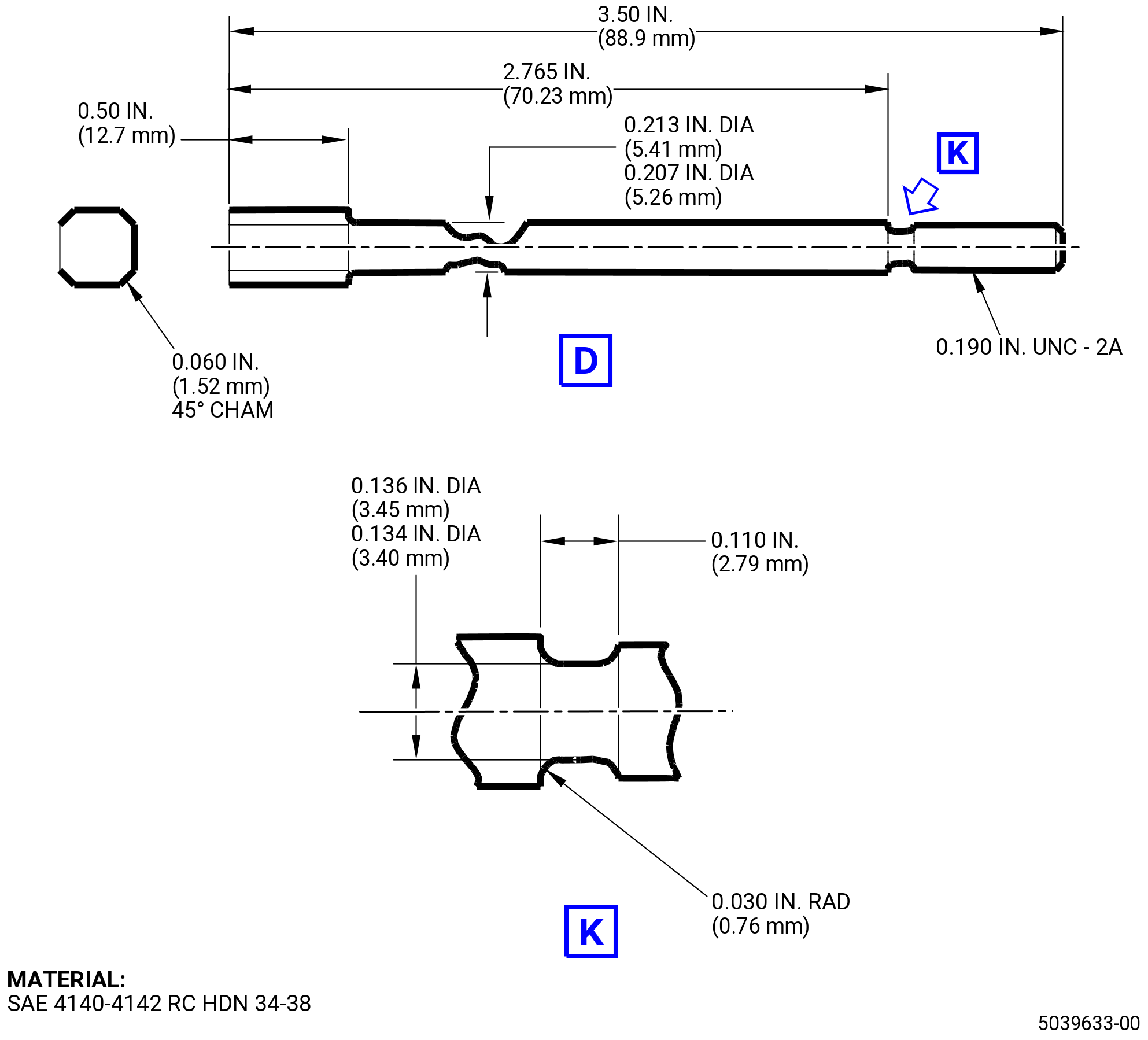
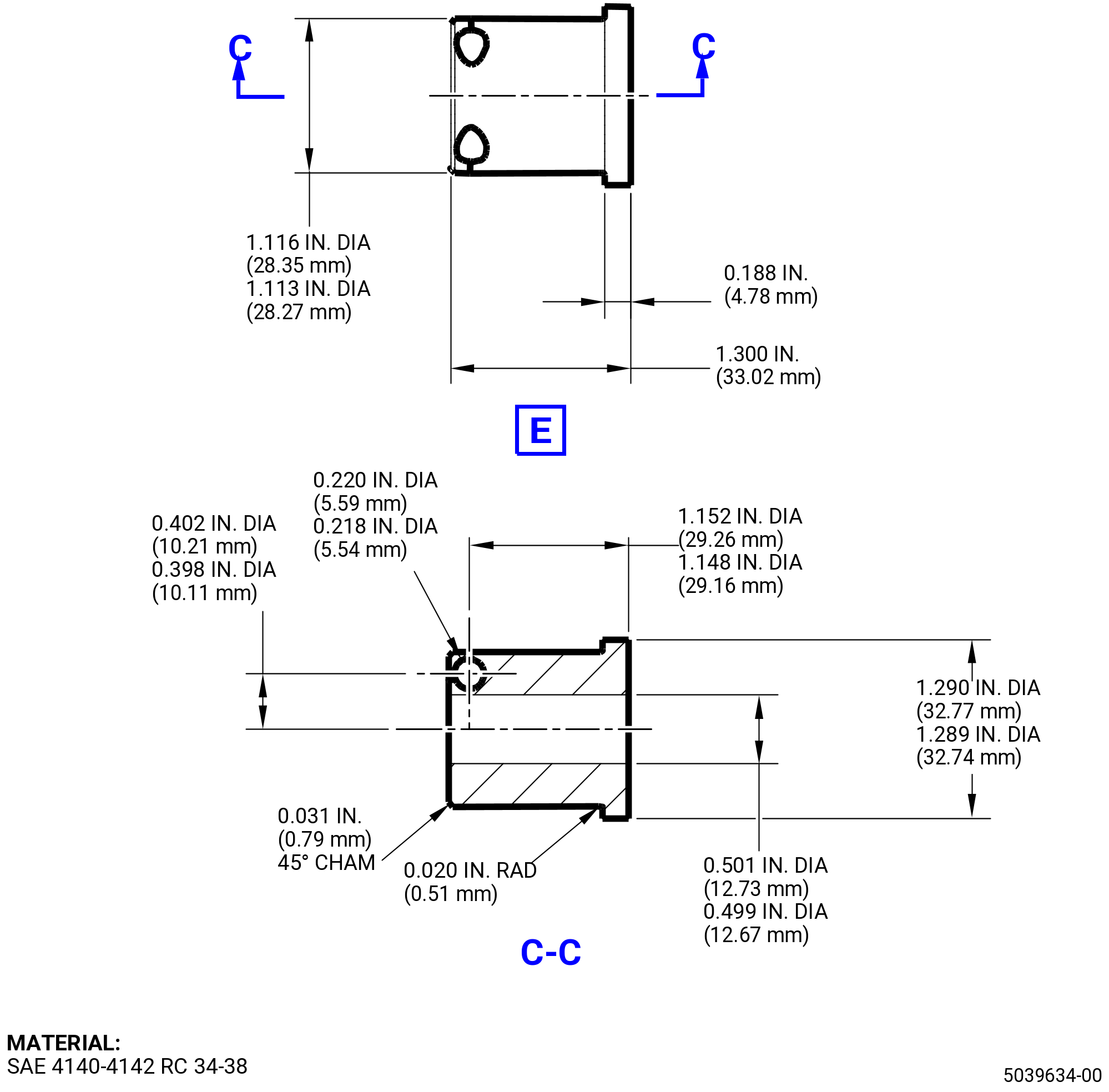
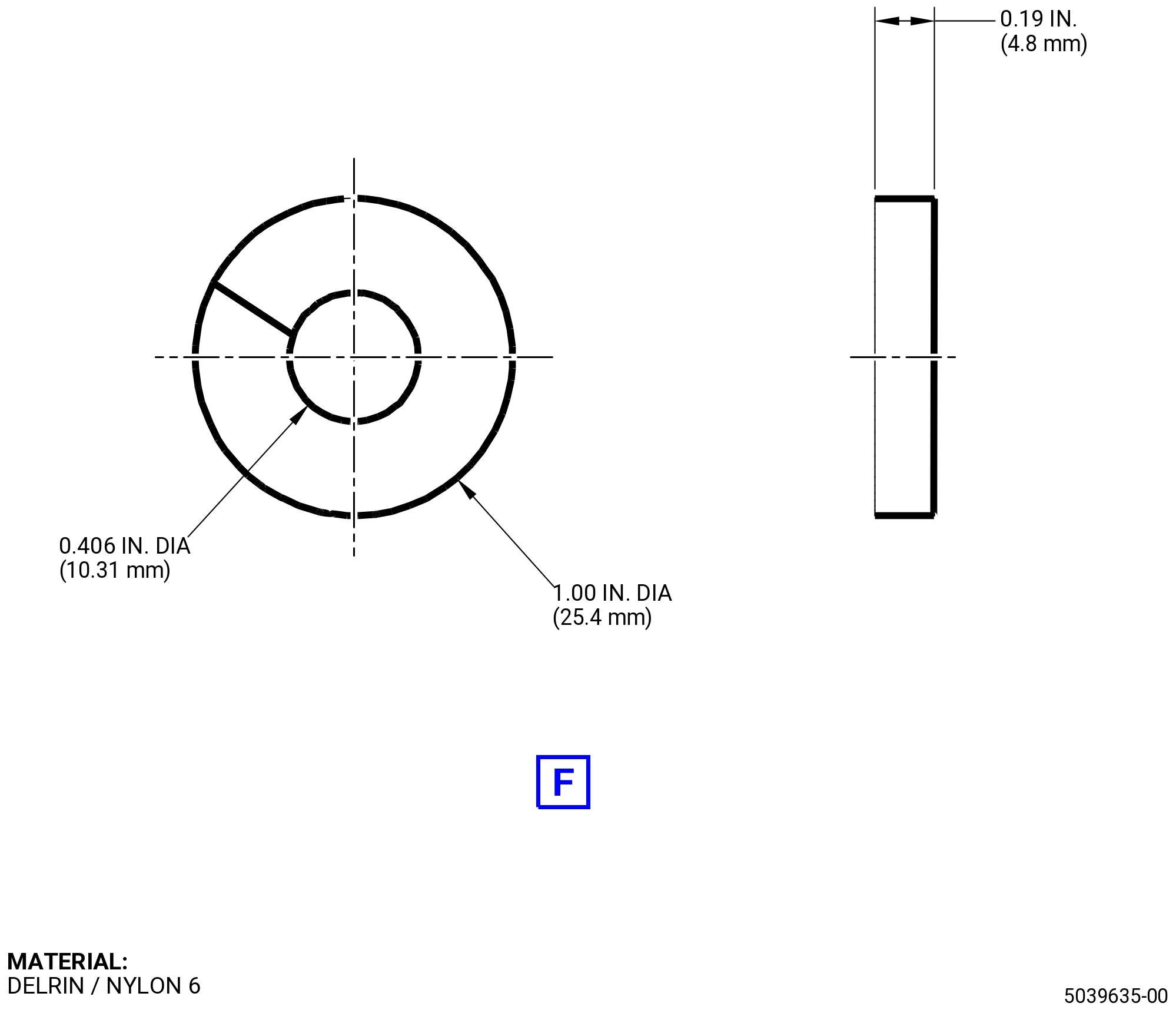
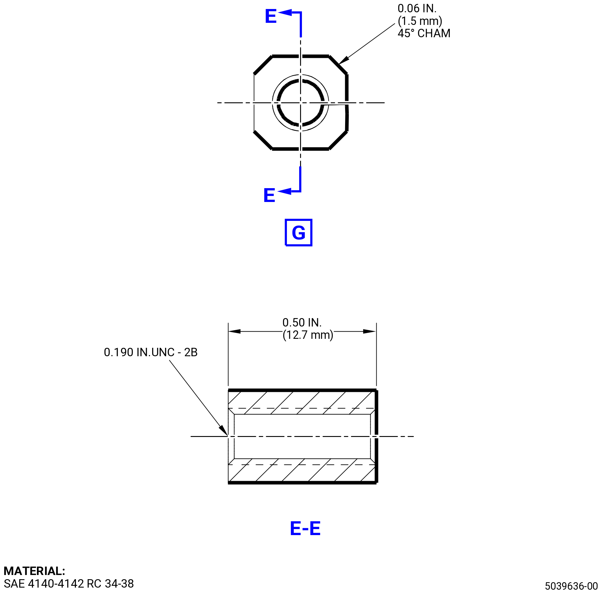
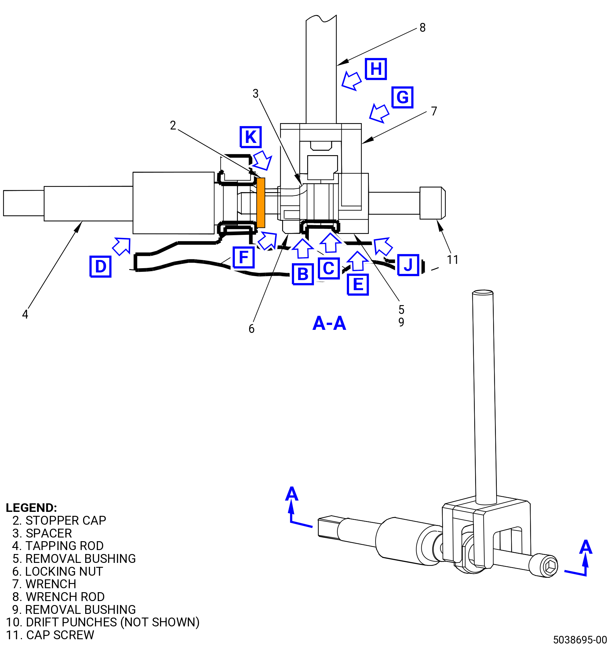
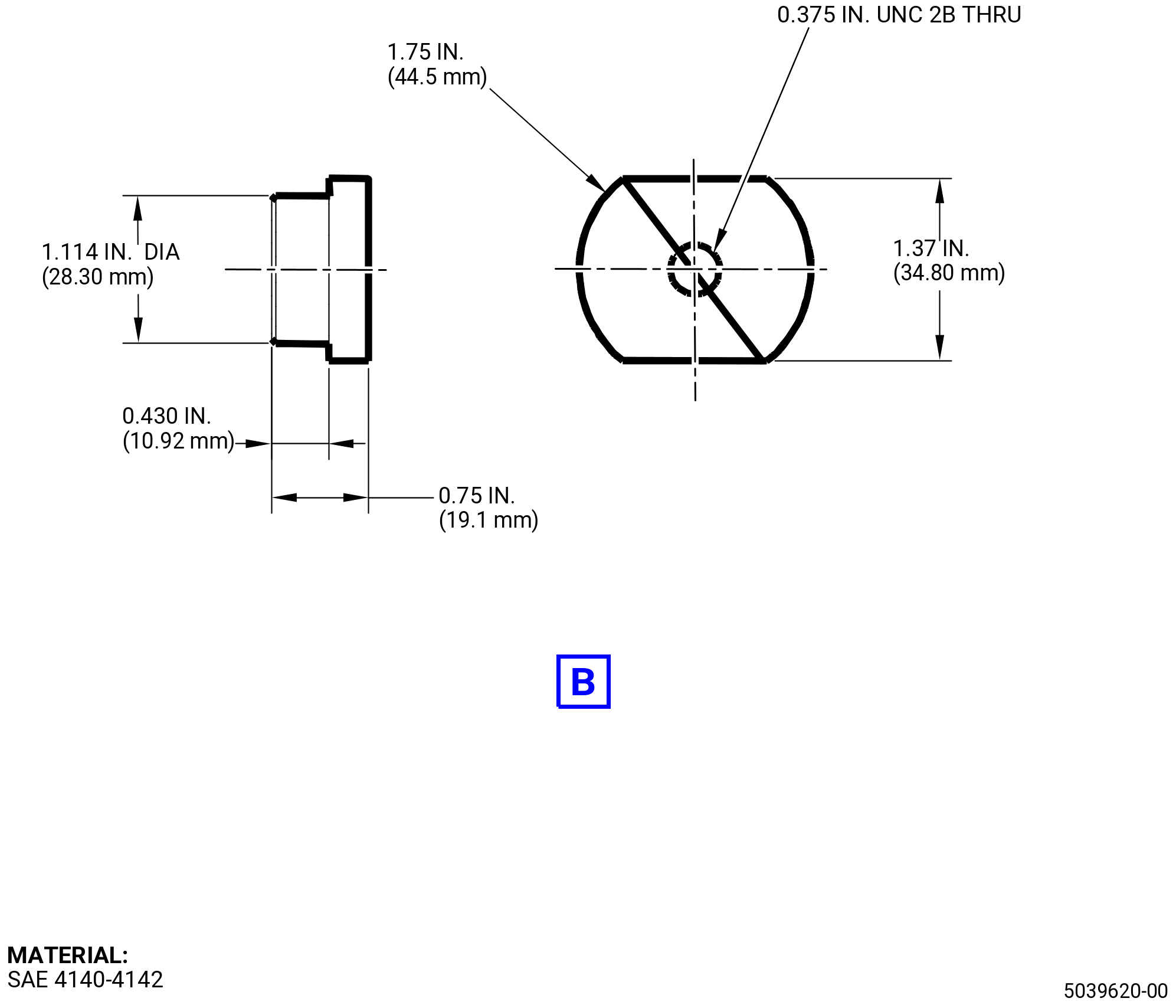
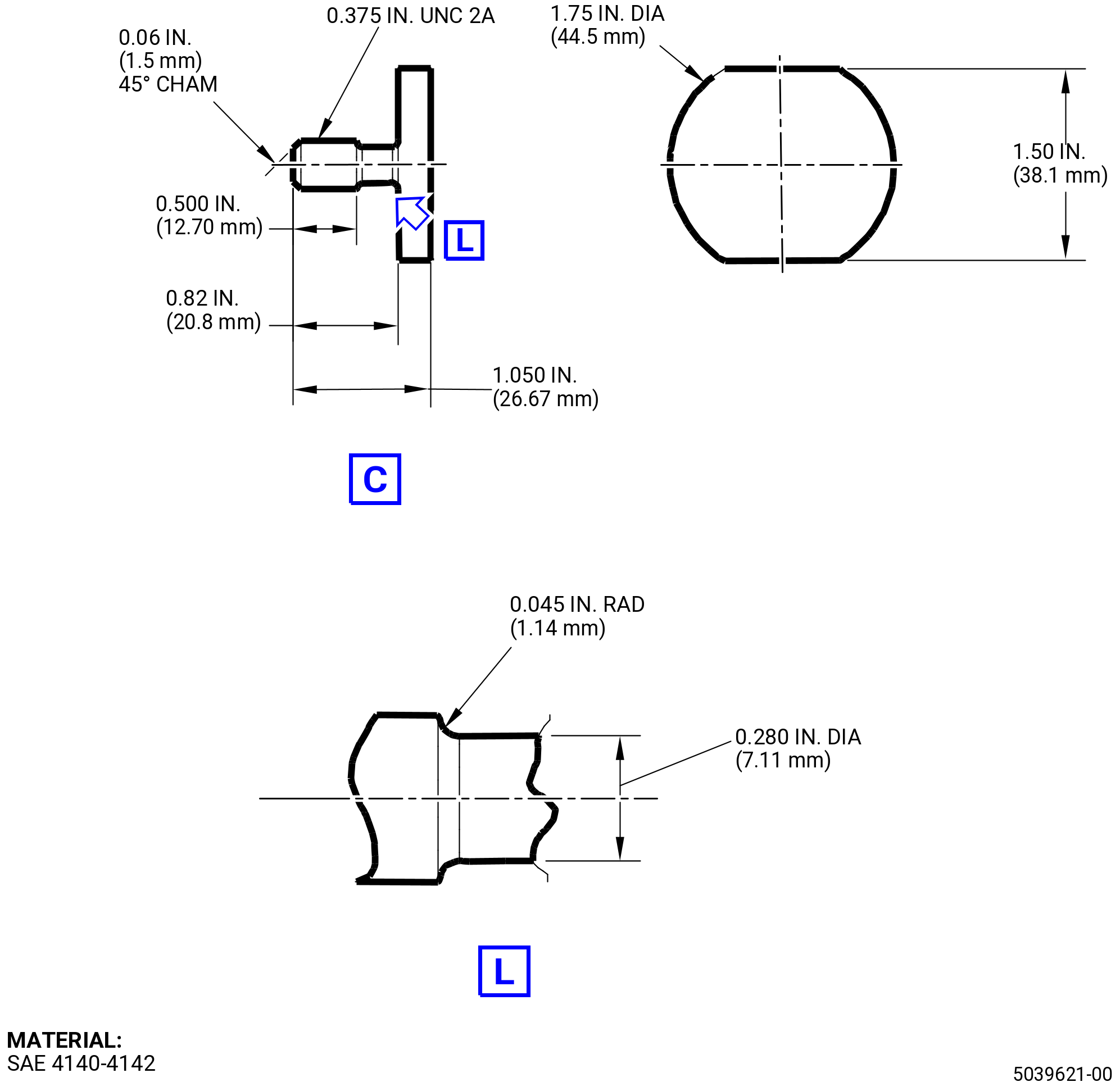
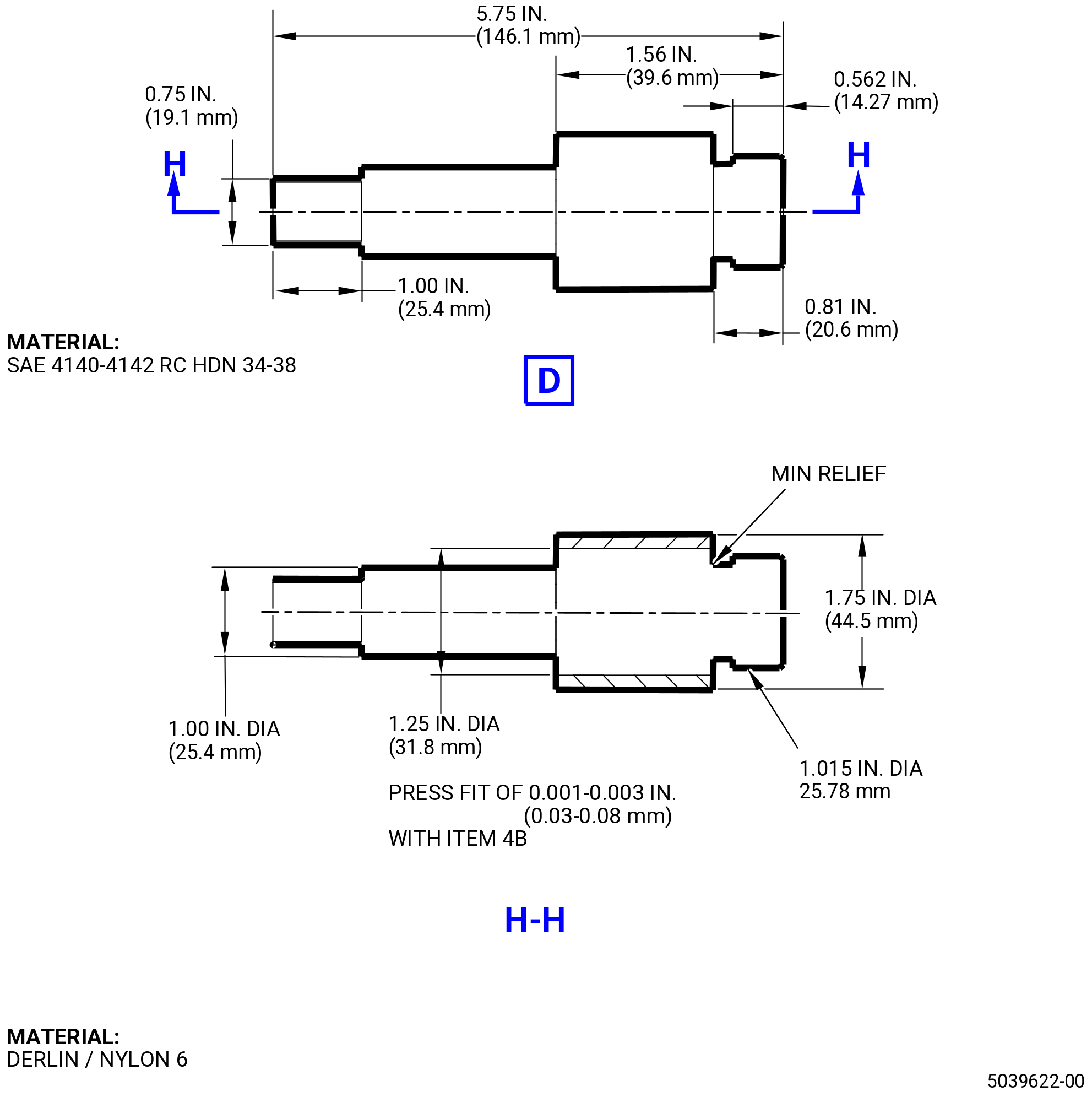
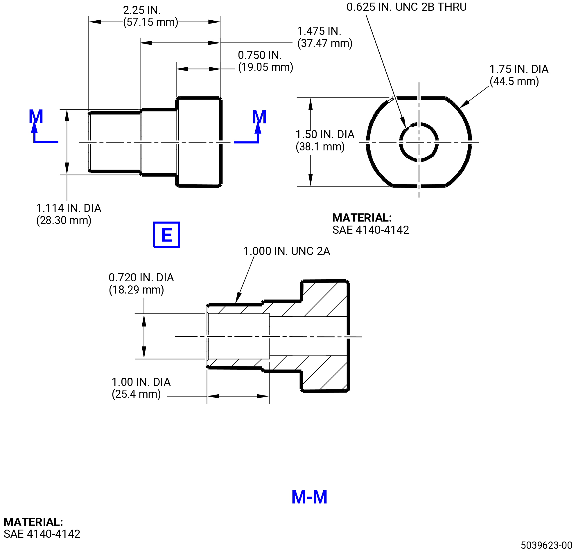
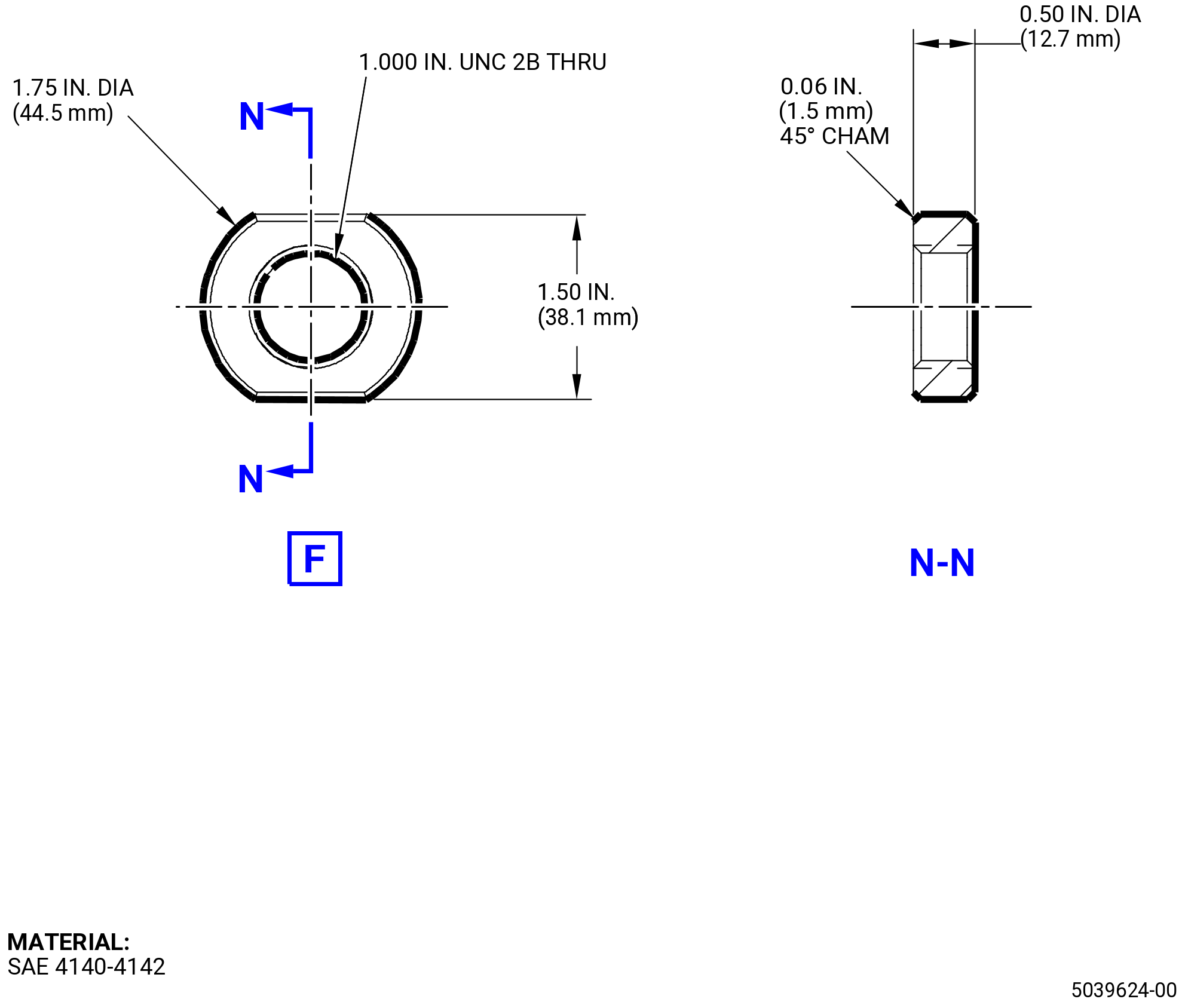
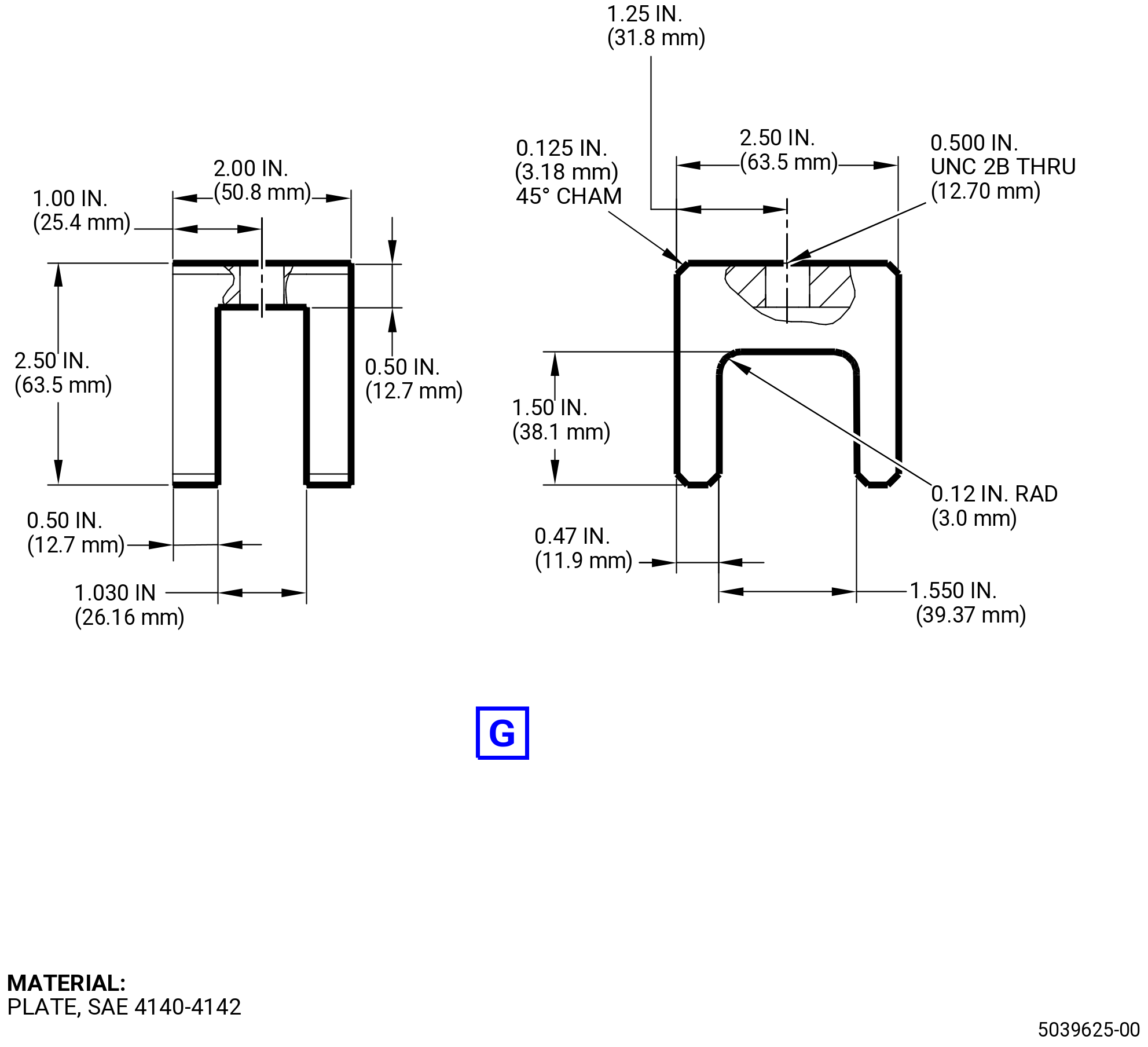
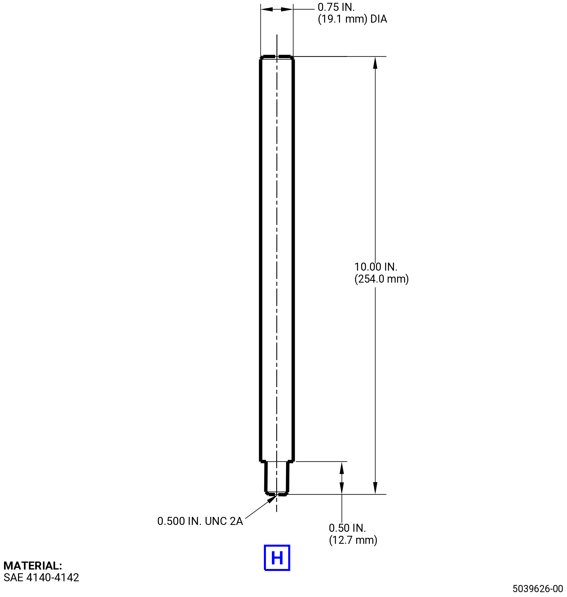
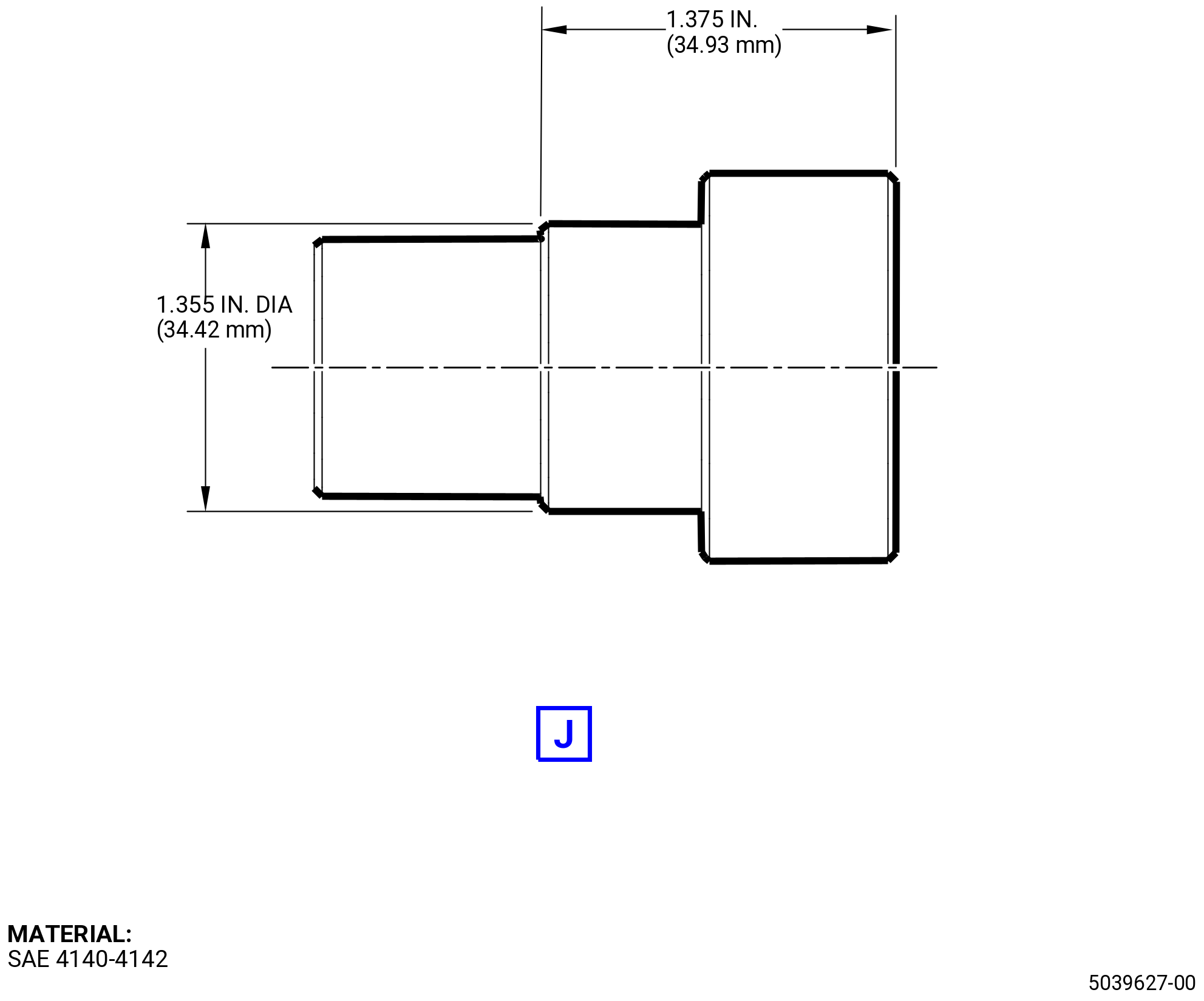
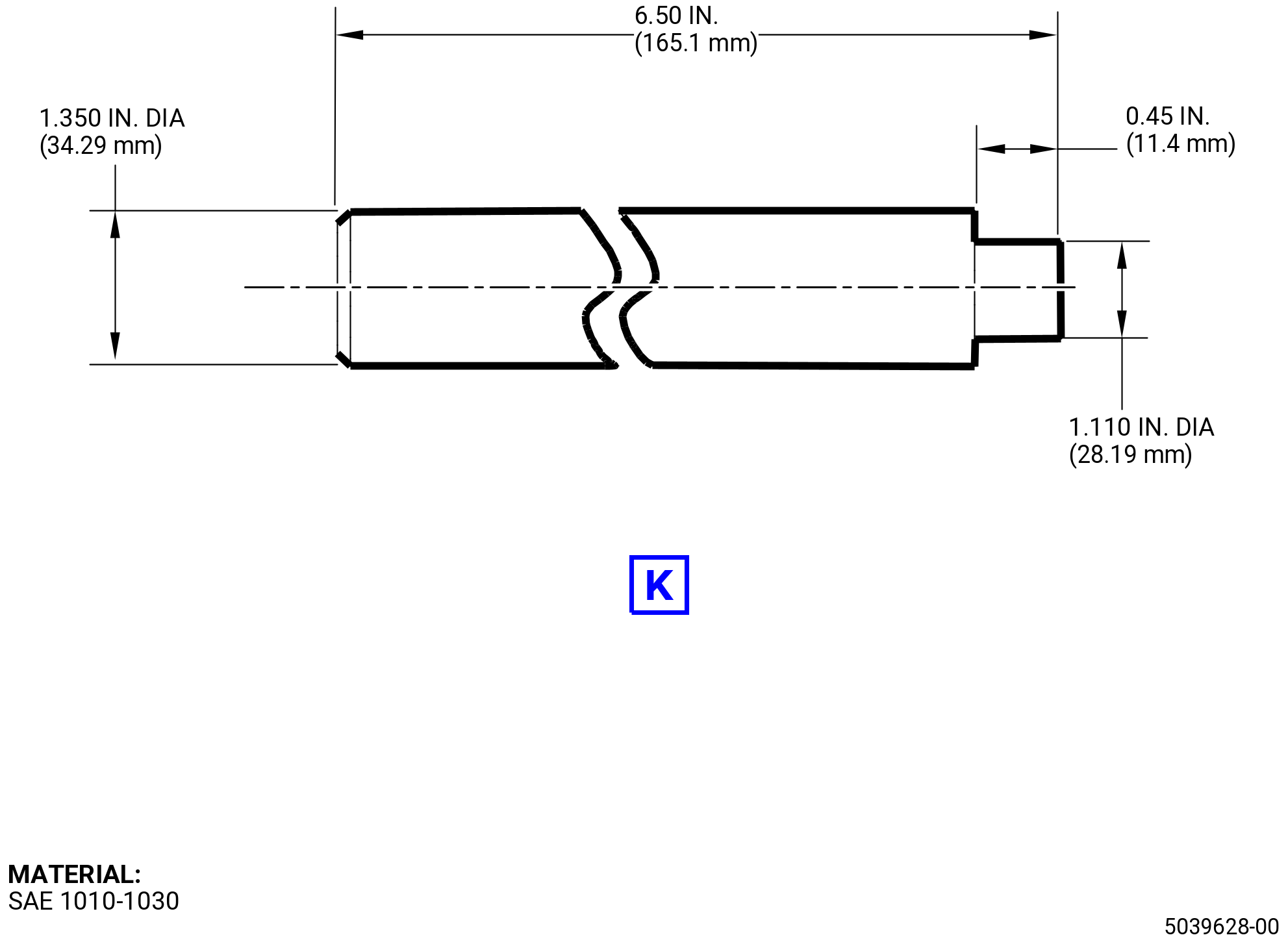
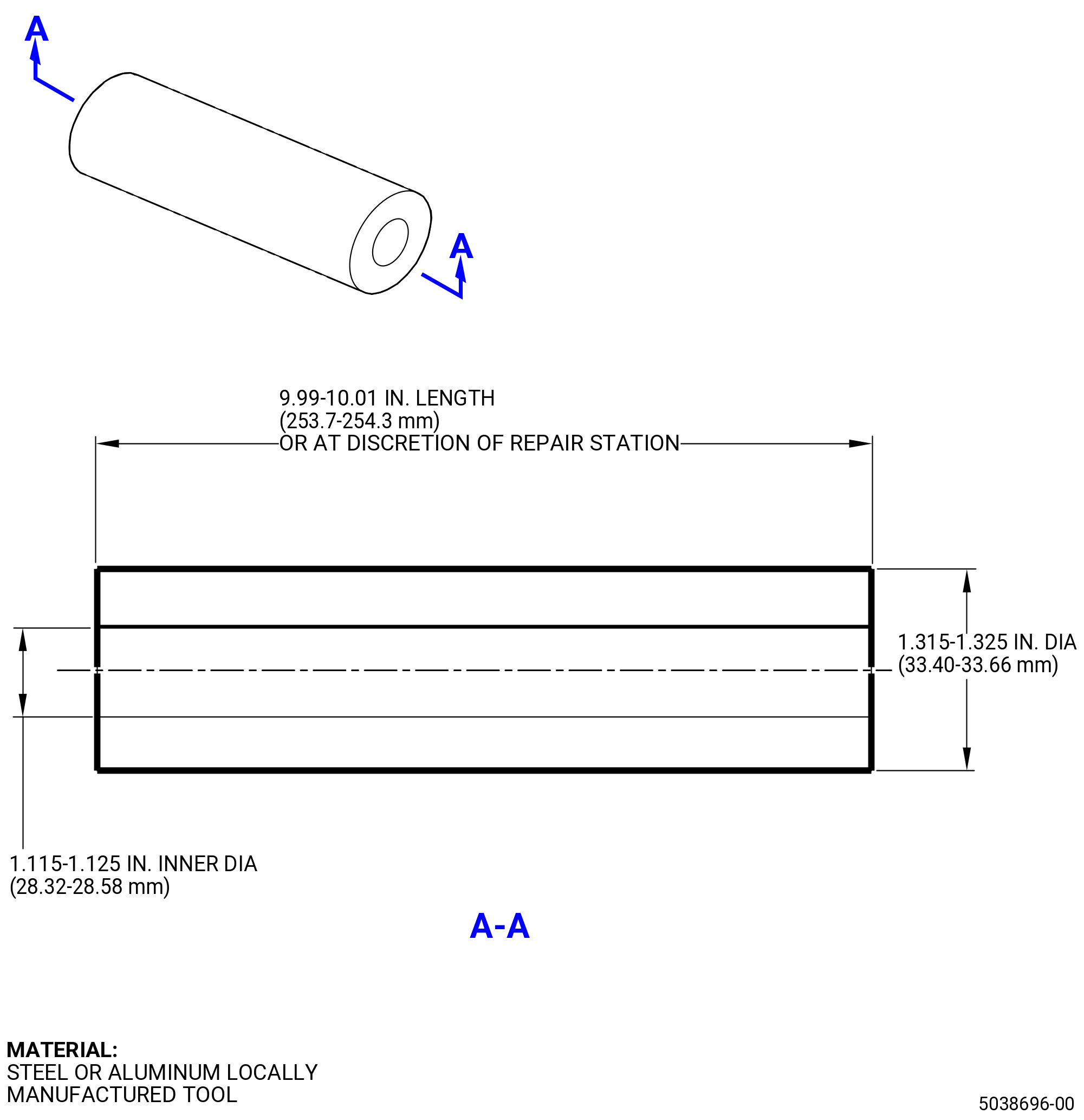
| (3) | Locally Manufactured Tools. |
| B. | Consumable Materials. |
|
| C. | Referenced Procedures. |
|
| D. | Expendable Parts. P/N 2327M58P01 is bushing for LH/RH clevis. P/N 2327M58P02 is bushing for center clevis. |
| E. | SPD Information. None. |
| F. | Special Solutions. None. |
| G. | Test Specimens. None. |
| 3 . | Dimensional Information. |
| Subtask 72-00-01-220-037 |
| A. | Refer to TASK 72-00-01-200-801 (72-00-01, INSPECTION 001) and TASK 72-21-06-200-801 (72-21-06, INSPECTION 001). |
| 4 . | Setup Information. |
| Subtask 72-00-01-440-002 |
| A. | This procedure can be performed with the forward engine mount yoke removed. Refer to Figure 202, Figure 203, Figure 204, Figure 207, Figure 208, and Figure 209, for local tool details. |
| 5 . | Procedure. |
| Subtask 72-00-01-050-002 |
| A. | Remove the RH/LH clevis outer bushings as follows: |
| (1) | Refer to 3Figure 201. If the RH/LH outer bushing is migrated, please follow the steps below. If the inner bushing in the same clevis is migrated, then also the outer bushing needs to be removed. If this is not needed, skip this step. |
| CAUTION: |
|
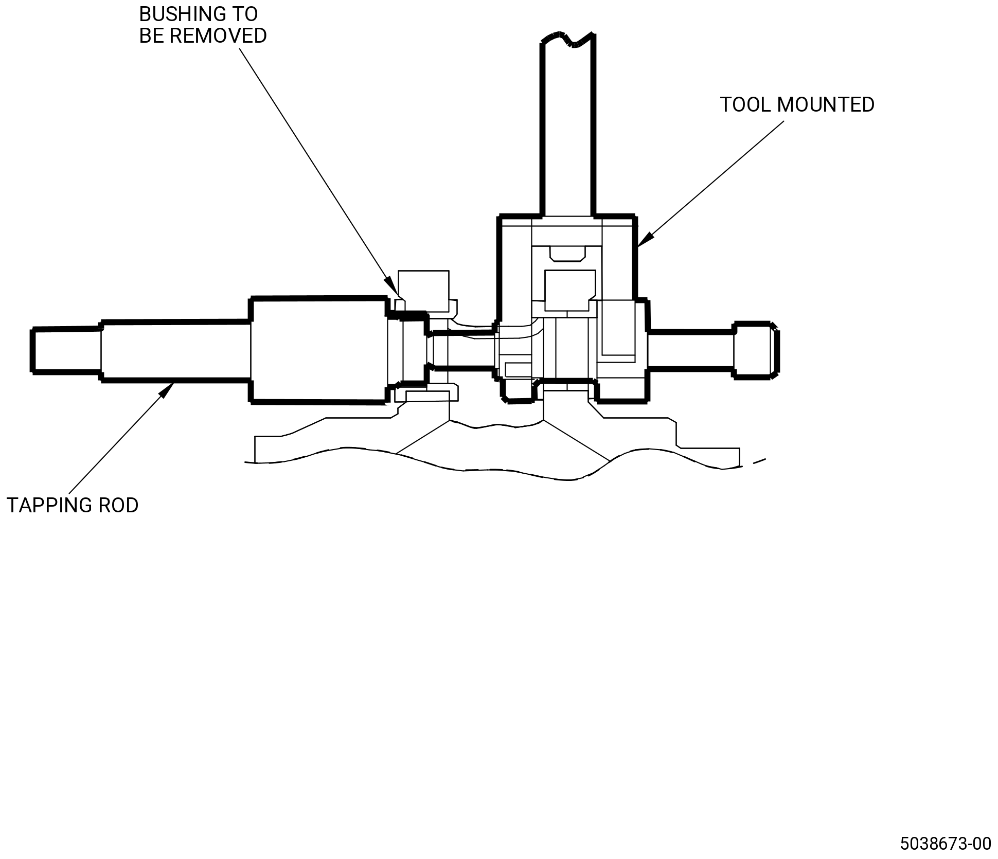
| (2) | With a tapping rod engage the tapping rod bit into the bushing approximately 0.375 inch (9.525 mm) in length. This needs to be engaged in the bushing which we are removing. Refer to Figure 201 |
| (3) | Attach the removal bushing (item 5) and the locking nut (item 6) into the other side of the RH/LH clevis. If we are removing the forward outer bushing, then these must be attached with the aft side or vice versa. Refer to Figure 201 and Figure 208. |
| (4) | Install the wrench rod (item 8) and the wrench (item 7) on the removal bushing (item 5) and the locking nut (item 6). Refer Figure 208. |
| (5) | Make sure to hold the wrench rod (item 8) still while torquing the cap screw (item 11). |
| (6) | Start torquing the cap screw (item 11) on the removal bushing (item 5) so that it keeps passing through the locking nut (item 6). Keep tightening this cap screw until it touches the tapping rod (item 4) installed on other end of the clevis. |
| (7) | Start torquing with the wrench slowly. The outer bushing will pop out from the other end. |
| Subtask 72-00-01-050-003 |
| B. | Remove the RH/LH clevis inner bushings as follows: |
| (1) | If the RH/LH inner bushing is your migrated bushing, refer to Figure 210, please follow the steps below. If this is not needed, skip this step. |
| NOTE: |
|
| (2) | Remove the outer bushing first. Refer to Subtask 72-00-01-050-002 (paragraph 5.A.). |
| NOTE: |
|
| CAUTION: |
|
| (3) | Tap the inner bushing with the locally manufactured tool, refer to Figure 209. |
| (4) | Keep tapping slowly until the inner bushing comes out of the clevis. |
| Subtask 72-00-01-050-004 |
| C. | Remove the center clevis bushings as follows: |
| (1) | If the center clevis bushing is your migrated bushing, refer to Figure 210, please follow the steps below. If this is not needed, skip this step. |
| CAUTION: |
|
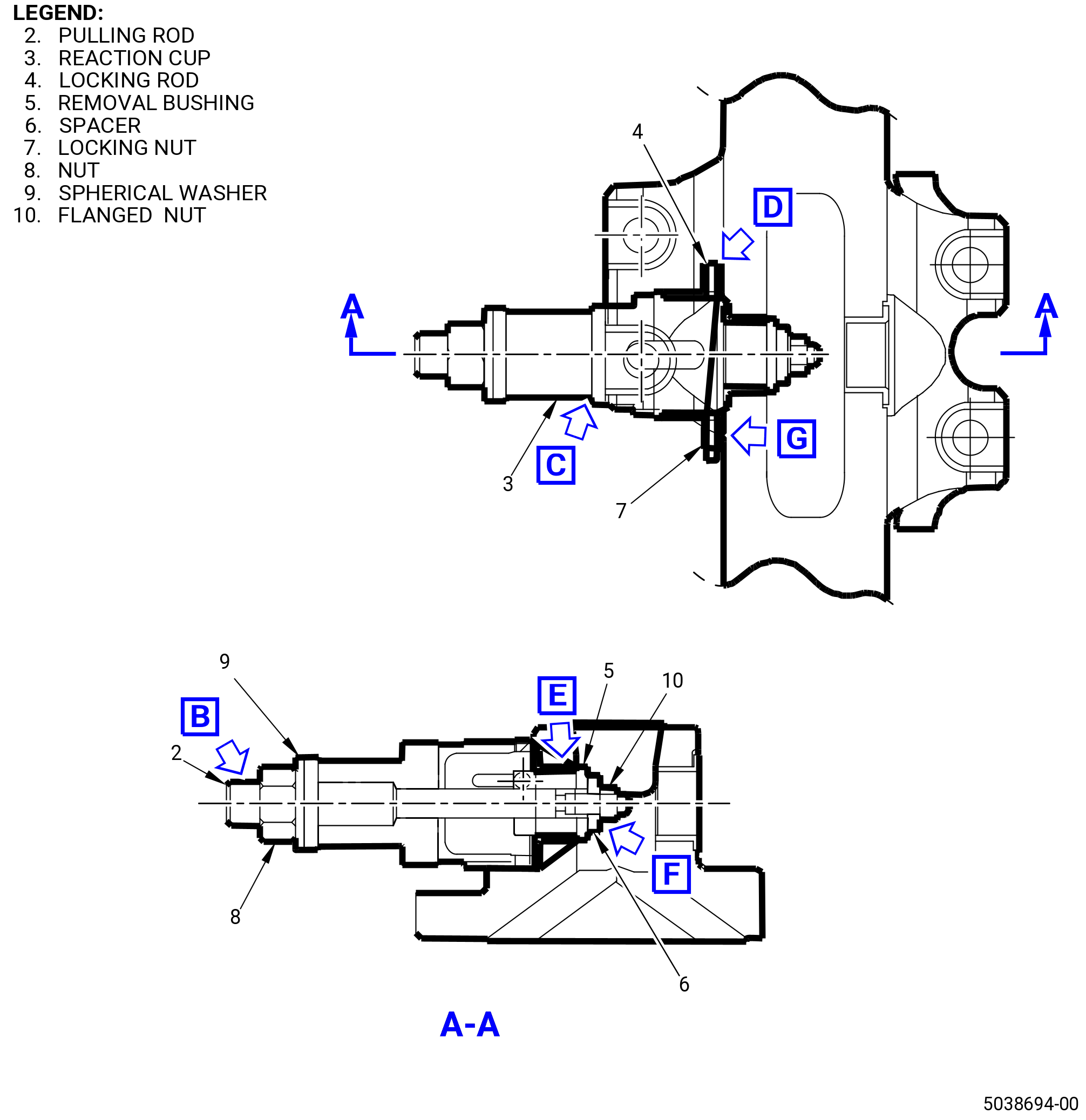
| (2) | Install the bushing removal tool assembly on the forward or aft side of the center clevis. Refer to Figure 207. |
| (3) | After the assembly of the tool, hold the flanged nut (item 10) with local tool and keep tightening the wrench rod (item 8) with the wrench slowly. This way the bushing will pop out. |
| Subtask 72-00-01-220-038 |
| D. | Cleaning and dimensional inspection post bushing removal: |
| Subtask 72-00-01-160-003 |
| WARNING: |
|
| (1) | Clean the yoke bore with C04-003 acetone after the bushing removal. Make sure that all machined chips are cleared away and the bore is clean of any unwanted material. |
| Subtask 72-00-01-220-039 |
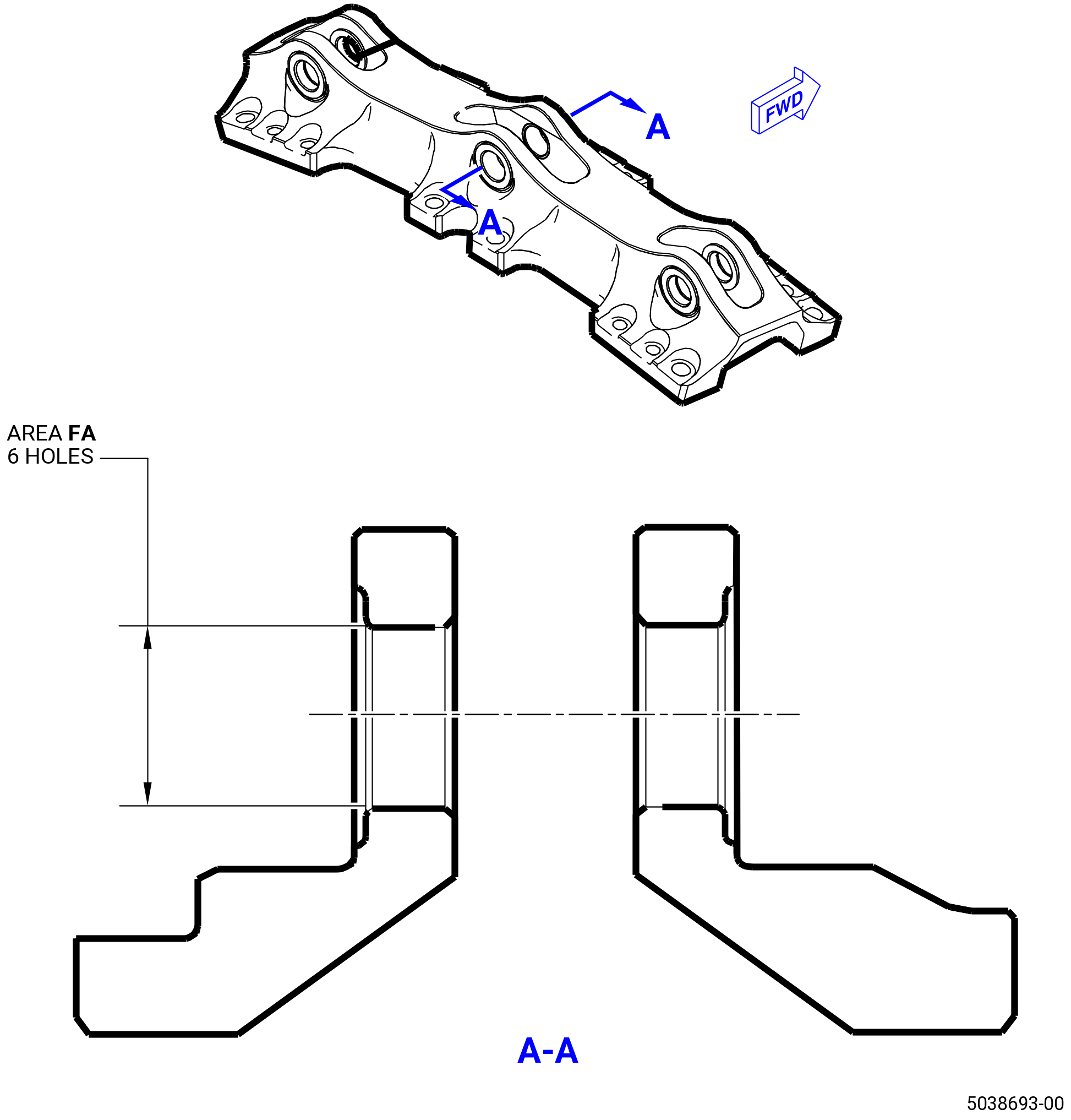
| (2) | Do a dimensional inspection of the yoke bores. Refer to Figure 206 and as follows: |
| (a) | Use a dial bore gage with a dial that shows 0.0001 inch (0.003 mm) increments. |
| (b) | Measure diameters at two axial locations of 0.25 inch (6.4 mm) apart in the inner side of each yoke bore. |
| (c) | Make two diameter measurements at each axial location, spaced 90 degrees apart. |
| (d) | Find if each bore diameter is in the limit of 1.3641-1.3649 inches (34.648-34.668 mm) in the LH/RH clevis and 1.3241-1.3249 inches (33.632-33.652 mm) in the center clevis. |
| (3) | After the bushing removal, inspect the yoke bores for nicks and scratches with the following acceptability limits: |
| Maximum serviceable limit: |
|
| Maximum repairable limit: |
|
| Repair method: |
|
| Subtask 72-00-01-230-001 |
| (4) | Do a fluorescent-penetrant inspection (FPI) of the yoke bore diameter as follows: |
| Subtask 72-00-01-110-001 |
| (a) | Etch bore inner diameter (ID). Refer to TASK 70-24-00-110-033 (70-24-00, ETCHING PROCEDURES FOR FLUORESCENT-PENETRANT INSPECTION), Class B. |
| Subtask 72-00-01-230-002 |
| (b) | Do a FPI bore ID. Refer to TASK 70-32-02-230-001 (70-32-02, FLUORESCENT PENETRANT INSPECTION), Class G. |
| (c) | Refer to TASK 72-21-06-200-801 (72-21-06, INSPECTION 001) for FPI limits for mount yoke serviceability. |
| (d) | Refer to TASK 72-21-06-200-801 (72-21-06, INSPECTION 001) for other limits of mount yoke serviceability. |
| Subtask 72-00-01-440-003 |
| E. | Install the replacement bushing as follows: |
| NOTE: |
|
| (1) | Use the bushing P/N 2327M58P01 for LH/RH clevis and the bushing P/N 2327M58P02 for center clevis. |
| (2) | Install the new bushing to its original position as follows: |
| Subtask 72-00-01-930-001 |
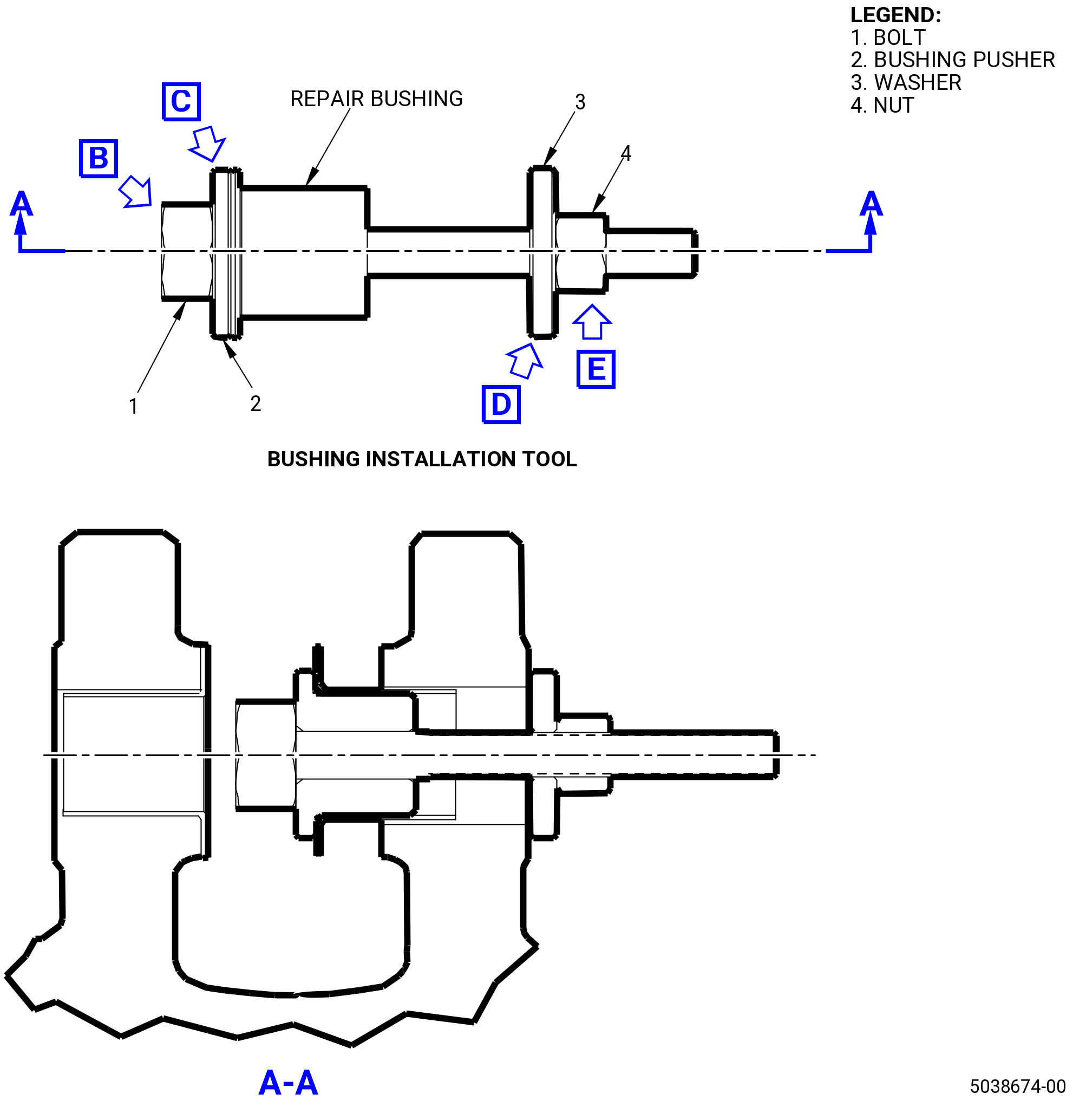
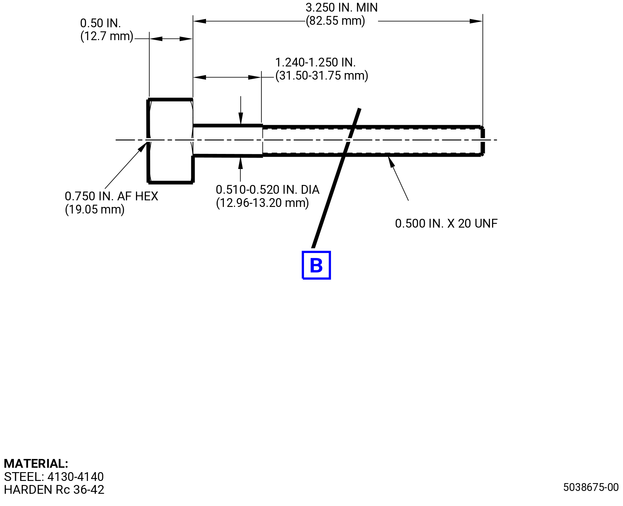
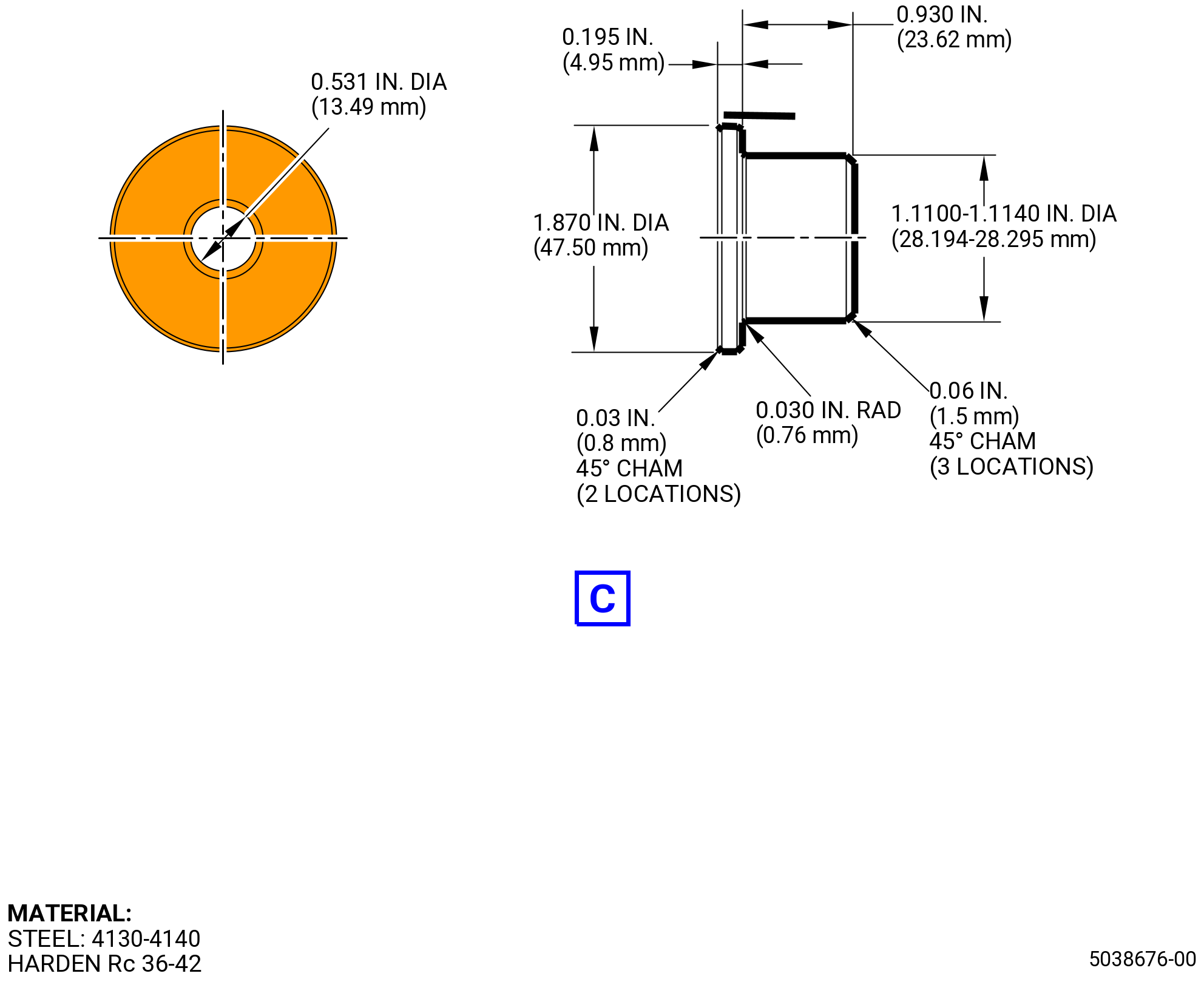
| (a) | If necessary, make the bushing installation tool. Refer to Figure 202. |
| Subtask 72-00-01-350-002 |
| WARNING: |
|
| WARNING: |
|
| WARNING: |
|
| (b) | Chill the migrated bushing with dry ice and C04-035 isopropyl alcohol for at least 30 minutes before it is pushed back into its correct position. |
| (c) | Apply a thin coat of C02-071 lubricant or C02-060 lubricant around the exposed bore area before to push the bushing back. |
| Subtask 72-00-01-440-004 |
| (d) | Install the bushing pusher (item 2) in the migrated bushing. Refer to Figure 202. |
| (e) | Install the bolt (item 1) through the bushing pusher (item 2) and mount lug. Refer to Figure 202 and do as follows: |
| 1 | Install the bolt (item 1) from the face of the mount lug that you will not repair. |
| (f) | Install the washer (item 3) and nut (item 4) to the face of the mount lug that you will repair. Refer to Figure 202 and do as follows: |
| 1 | Install the washer (item 3) to the bolt (item 1) at the face of the mount lug. |
| 2 | Install the nut (item 4) to the bolt (item 1) from the face of the mount lug to force the washer (item 3) against the mount lug face. |
| (g) | Install the lug spacer between the mount lugs and use C10-155 shims as necessary to eliminate axial clearance between the lug spacer and the mount lugs. Refer to Figure 203. |
| (h) | Let the flanged bushing get to room temperature at a range of 65 to 85°F (18 to 29°C). |
| (i) | Remove excess lubricant after the final assembly. |
| (j) | Use bushing P/N 2327M58P01 for LH/RH clevis and bushing P/N 2327M58P02 for center clevis. |
| (k) | A line boring operation needs to be performed on the bushings ID after the bushings P/N 2327M58P01 or P/N 2327M58P02 are installed. |
| 1 | A line boring pass must be made through all bushings in forward and aft lugs of each clevis. In case of LH/RH clevis, line boring pass must be made through all four bushings, and in case of center clevis, it must be made through the two bushings in forward and aft clevis lugs. |
| 2 | The bushing P/N 2327M58P01 or P/N 2327M58P02 has ID equal to 1.1225 inches (28.512 mm) nominal, after line boring the ID must have a finished diameter of 1.125-1.126 inches (28.58-28.60 mm). |
| Subtask 72-00-01-160-004 |
| WARNING: |
|
| (l) | Full clean-up with C04-003 acetone required after line boring. |
| NOTE: |
|
| Subtask 72-00-01-210-003 |
| F. | Do a pin tests inspection. Refer to Figure 204 and do as follows: |
| (1) | A pin of 1.1240 inches (28.549 mm) nominal must pass thru installed bushings P/N 2327M58P01 or P/N 2327M58P02 simultaneously and rotate with finger torque. |
| Subtask 72-00-01-220-040 |
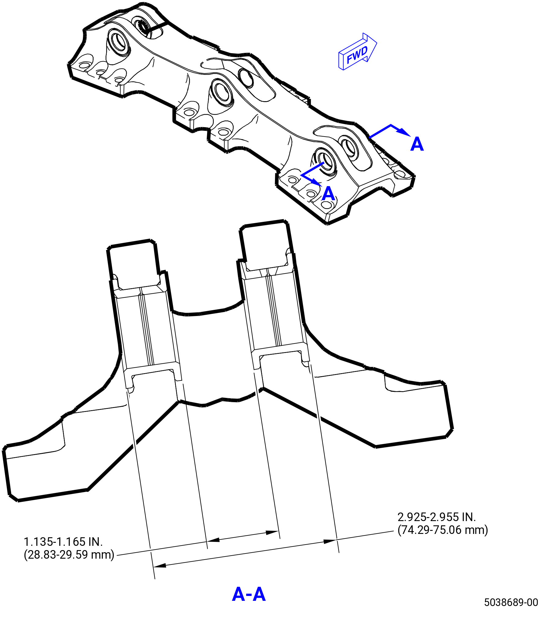
| G. | Do a dimensional inspection of the mount yoke, if it is applicable to RH/LH clevis. Refer to Figure 205 and do as follows: |
| (1) | The distance between the bushing shoulder surface of outer bushings must be 2.925-2.955 inches (74.29-75.06 mm). |
| (2) | The distance between the bushing shoulder surface of inner bushings must be 1.135-1.165 inches (28.83-29.59 mm). |
| Subtask 72-00-01-220-041 |
| H. | Do an inspection of the forward engine mount yoke bushing. Refer to TASK 72-00-01-200-801 (72-00-01, INSPECTION 001) and TASK 72-21-06-200-801 (72-21-06, INSPECTION 001). |
| Subtask 72-00-01-160-005 |
| I. | Clean the mount yoke. Refer to TASK 72-21-06-100-801 (72-21-06, CLEANING 001). |
| NOTE: |
|
| Subtask 72-00-01-440-005 |
| J. | If the forward yoke was removed, re-install the forward yoke. Refer to TASK 72-21-00-440-804 (72-21-00, ASSEMBLY 001), TASK 72-00-01-200-801 (72-00-01, INSPECTION 001), TASK 72-21-06-200-801 (72-21-06, INSPECTION 001), and follow the applicable limits. |