| GENX-1B ENGINE MANUAL | Dated: 04/05/2023 | |
| EM 72-23-00 , DISASSEMBLY 001 | ||
| NO. 1 BEARING ASSEMBLY - DISASSEMBLY 001 | ||
| GENX-1B ENGINE MANUAL | Dated: 04/05/2023 | |
| EM 72-23-00 , DISASSEMBLY 001 | ||
| NO. 1 BEARING ASSEMBLY - DISASSEMBLY 001 | ||
| * * * FOR ALL |
| TASK 72-23-00-040-801 |
| 1 . | General. |
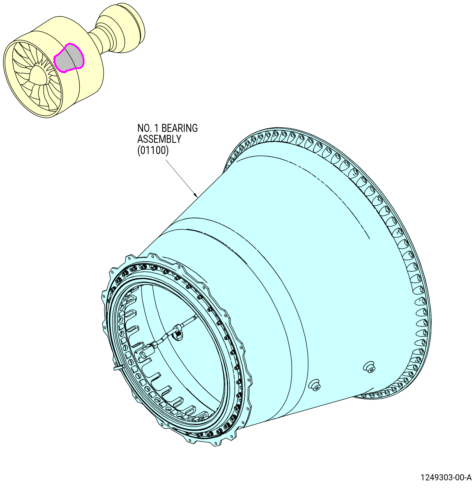
| A. | This procedure gives instructions to disassemble the No. 1 bearing assembly (01100). Refer to Figure 501. |
| B. | The No. 1 bearing assembly is on the 11C3205 assembly/disassembly stand. |
| C. | Bearings. |
| (1) | Be careful with the components of the No. 1 bearing assembly. Refer to TASK 70-14-00-620-003 (HANDLING OF BEARINGS) and TASK 70-60-01-620-002 (PRESERVATION OF ANTIFRICTION BEARINGS) . |
| (2) | Keep the bearing components (balls, cages, inner races, and outer races) as a set by serial number. The ball bearing is a matched assembly. Do not mix serviceable ball bearing components with the components of different serial numbers. |
| (3) | Do not touch the ball bearing components with bare hands. Wear clean, Latex C10-140 gloves when you touch bearing components. |
| (4) | Do not touch the cage or balls of the No. 1 bearing assembly with assembly/installation tools. |
| 2 . | Tools, Equipment, and Materials. |
| NOTE: |
|
| A. | Tools and Equipment. |
| (1) | Special Tools. |
| (2) | Standard Tools and Equipment. |
|
| (3) | Locally Manufactured Tools. None. |
| B. | Consumable Materials. |
|
| C. | Referenced Procedures. |
|
| D. | Expendable Parts. None. |
| 3 . | Procedure. |
| Subtask 72-23-00-040-010 |
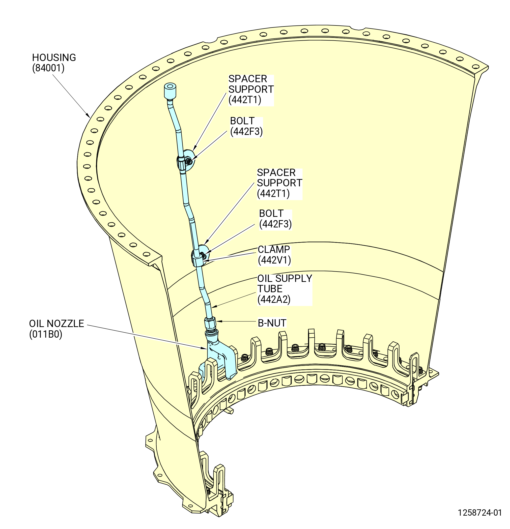
| A. | Remove the oil supply tube (442A2) from the No. 1 bearing housing (housing) (84001) as follows. Refer to Figure 502. |
| (1) | Remove the bolts (442F3), spacer supports (442T1), and clamp (442V1) from the oil supply tube. |
| (2) | Loosen the B-nut from the oil nozzle (011B0). |
| (3) | Remove the oil supply tube. |
| Subtask 72-23-00-040-007 |
| B. | Install the housing (01-180) (SIN 84001) with the roller bearing (01-160) (SIN 011A0) in the 9401M62 adjustable stand as follows: |
| CAUTION: |
|
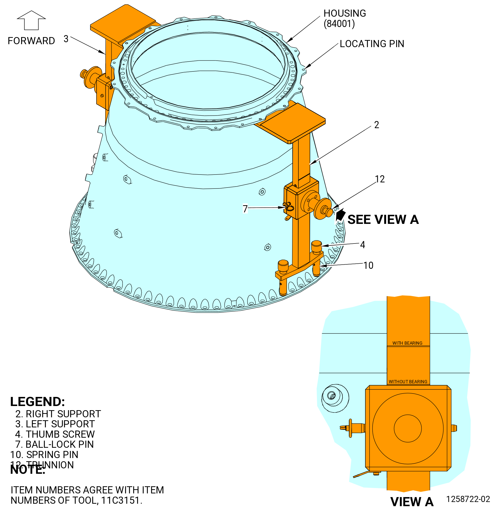
| (1) | Make sure that the trunnions (item 12) of the 11C3151 lift and turn fixture are aligned with the scribe line WITH BEARING on each of the support brackets (item 2 and item 3). If necessary, adjust the trunnions (item 12) as follows. Refer to Figure 504. |
| (a) | Remove the ball-lock pin (item 7) from the right/left support brackets (item 2 and item 3). |
| (b) | To lift the housing without the bearing installed, adjust the trunnion to the scribe line WITHOUT BEARING on the right/left support brackets (item 2 and item 3). |
| (c) | To lift the housing with the bearing installed, adjust the trunnion to the scribe line WITH BEARING on the right/left support brackets (item 2 and item 3). |
| (d) | Install the ball-lock pin (item 7) in the right/left support brackets (item 2 and item 3). |
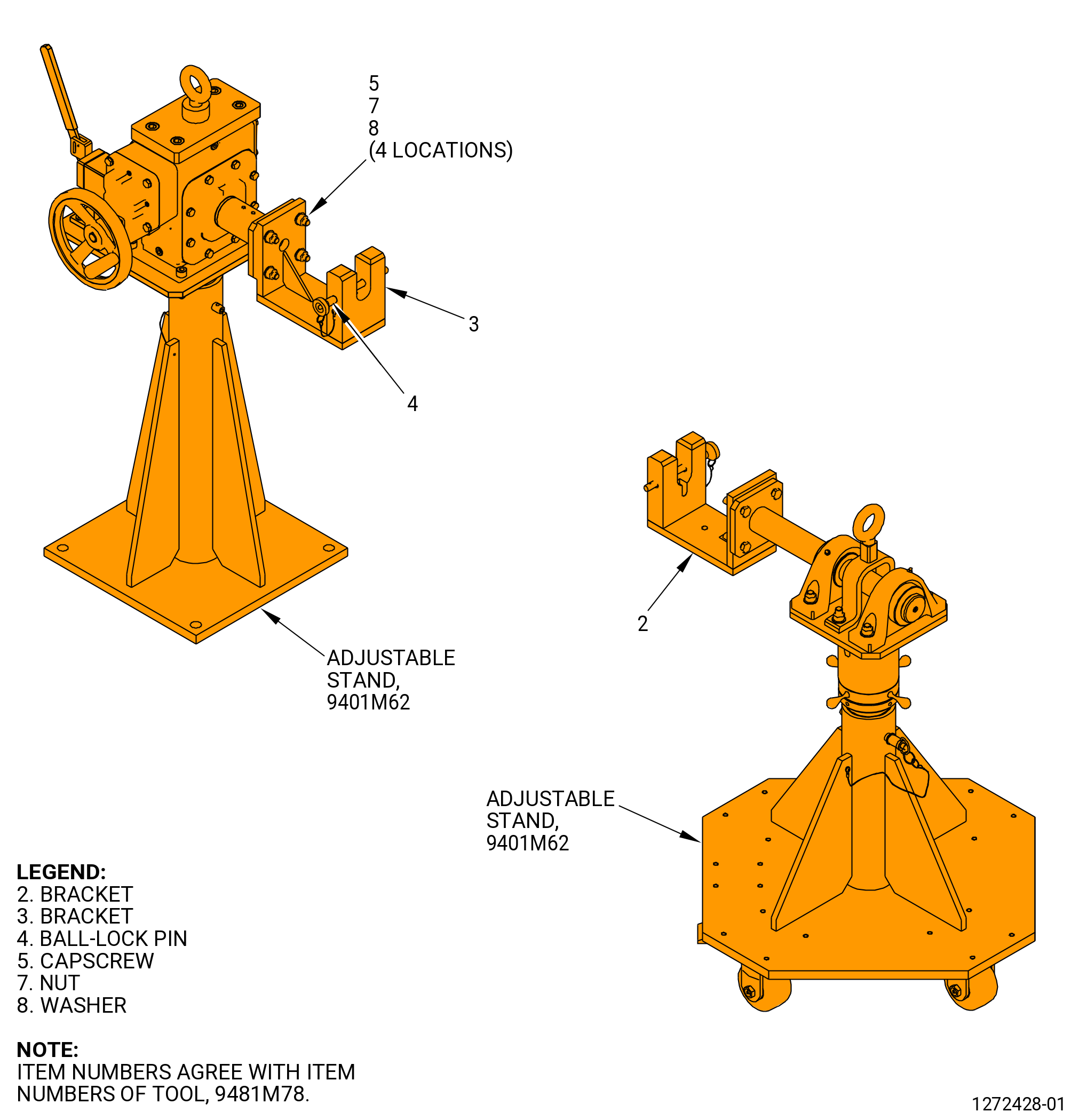
| (2) | Install the 9481M78 bracket adapter on the 9401M62 adjustable stand. Refer to Figure 505 and do as follows: |
| (a) | Put the bracket (item 3) on the stationary support of the 9401M62 adjustable stand. |
| (b) | Attach the bracket (item 3) with the capscrews (item 5), the washers (item 8), and the nuts (item 7) at four locations. Tighten the nuts (item 7). |
| (c) | Put the bracket (item 2) on the portable support of the 9401M62 adjustable stand. |
| (d) | Attach the bracket (item 3) with the capscrews (item 5), the washers (item 8), and the nuts (item 7) at four locations. Tighten the nuts (item 7). |
| (e) | Remove the ball-lock pins (item 4) from the brackets (item 2 and 3). |
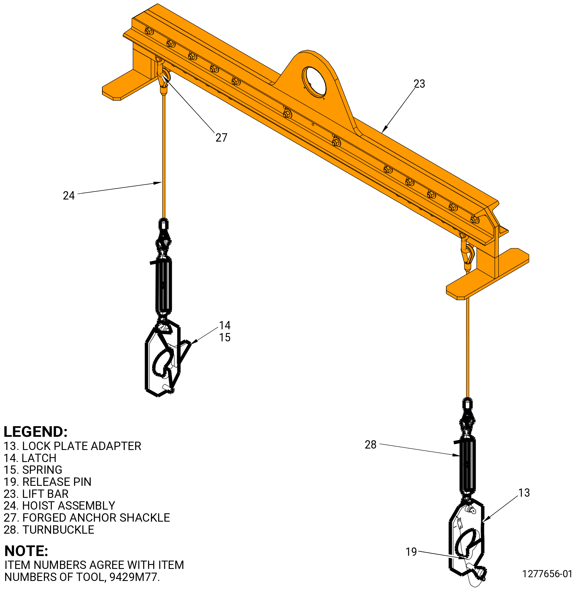
| (3) | Attach the 9429M77 lift/turn fixture to the 11C3151 lift and turn fixture. Refer to Figure 503 and Figure 504. |
| (a) | Attach the assembly hoist (item 24) to the lift bar (item 23), with the forged anchor shackles (item 27) of the 9429M77 lift/turn fixture, to the same quantity of holes on the right and left to keep the tool balanced. Make sure the assembly hoists (item 24) are perpendicular (at the right angle) to the lift bar (item 23) after connecting the 9429M77 lift/turn fixture to the 11C3151 lift and turn fixture. |
| (b) | Attach each lock plate adapter (item 13) of the 9429M77 lift/turn fixture from each assembly hoist (item 24) with the forged anchor shackles (item 27). |
| (c) | Push the latch (item 14) to let the lock plate adapter (item 13) to attach to each trunnion (item 12) of the 11C3151 lift and turn fixture. |
| (d) | Make sure the latch (item 14) of the 9429M77 lift/turn fixture engages the trunnion (item 12) of the 11C3151 lift and turn fixture and put the release pins (item 19) of the 9429M77 lift/turn fixture through the trunnion (item 12) of the 11C3151 lift and turn fixture and lock adapter plates (item 13) of the 9429M77 lift/turn fixture. |
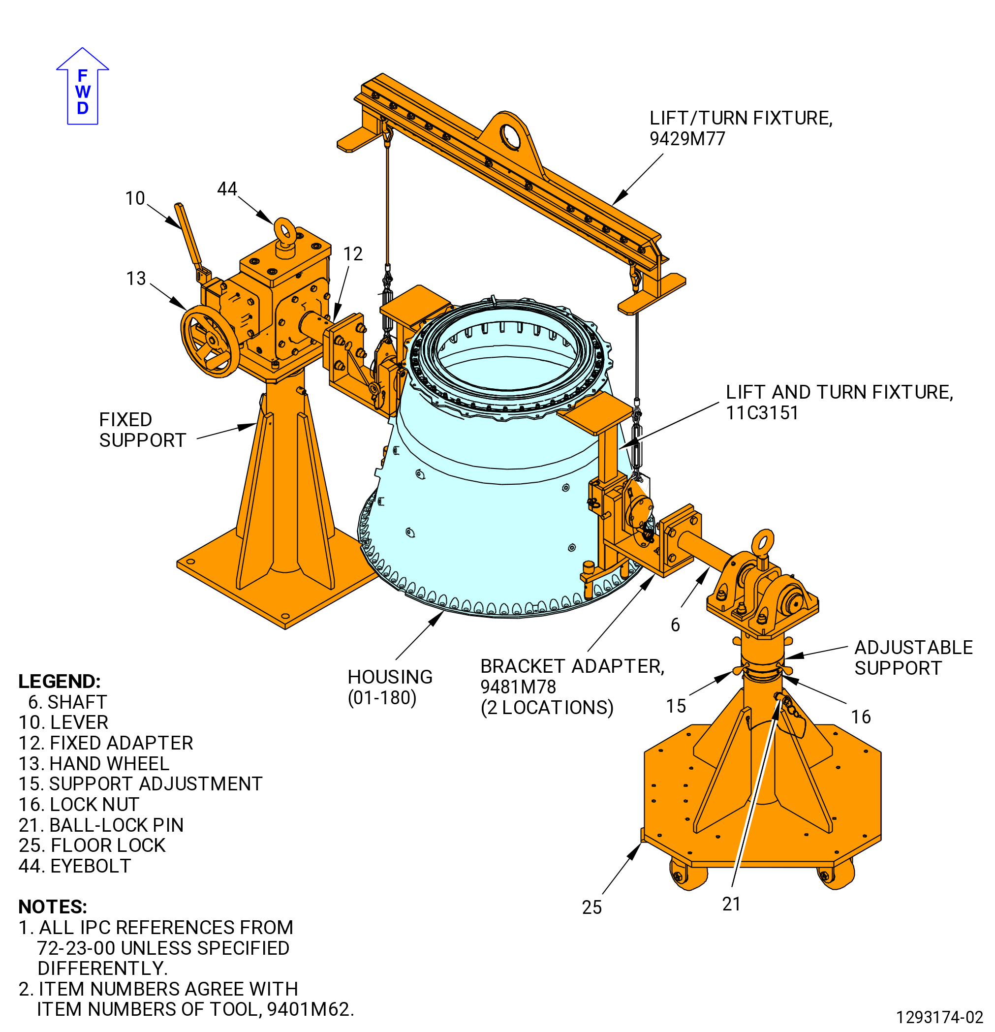
| (4) | Install the housing (01-180) (SIN 84001) on the 9401M62 adjustable stand. Refer to Figure 506 and do as follows: |
| (a) | Make sure the ball-lock pins (item 21) are installed at two locations on the fixed and adjustable supports. If necessary, adjust height of supports as follows: |
| 1 | Attach an overhead hoist to the eyebolt (item 44) and apply lift pressure to the support. |
| a | Lift the support to the necessary height and install the ball-lock pin (item 21). |
| 2 | Move the lever (item 10) to the outward position to lock the fixed adapter (item 12) to prevent its rotation. |
| WARNING: |
|
| 3 | Lift the housing in the 11C3151 lift and turn fixture. |
| 4 | Lower and align the trunnions (item 12) of the 11C3151 lift and turn fixture with the slots on the 9481M78 bracket adapter at two locations. Refer to Figure 504. |
| 5 | Make sure the housing is level, if necessary adjust as follows. Refer to Figure 506. |
| a | Loosen the lock nut (item 16) of the 9401M62 adjustable stand and turn the support adjustment (item 15) to adjust the height of the shaft (item 6) on the portable support. Make sure that the housing is level. |
| b | Tighten the lock nut (item 16). |
| 6 | Install the ball-lock pin (item 4) of the 9481M78 bracket adapter in the bracket (item 2) to secure the trunnion (item 12) of the 11C3151 lift and turn fixture. Refer to Figure 504. |
| 7 | Remove the 9429M77 lift/turn fixture from the trunnions on the 11C3151 lift and turn fixture. Refer to Figure 503 and Figure 504. |
| CAUTION: |
|
| 8 | Put the floor locks (item 25) of the 9401M62 adjustable stand down until they touch the floor. Refer to Figure 506. |
| 9 | Use the hand wheel (item 13) to rotate the housing. |
| CAUTION: |
|
| 10 | Move the lever (item 10) to the outward position to prevent rotation of the housing. |
| Subtask 72-23-00-040-008 |
| * * * PRE SB 72-0011 |
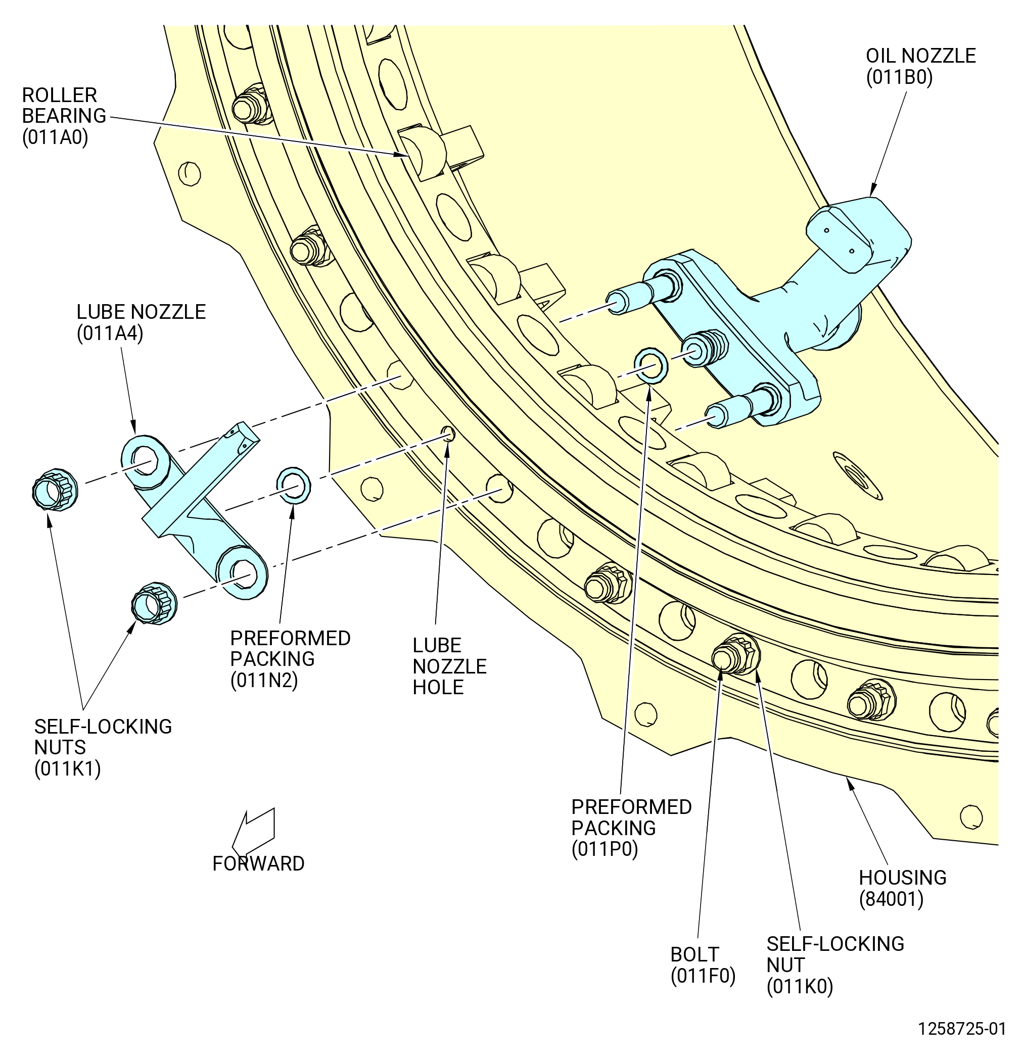
| C. | Remove the oil nozzle (011B0), the lube nozzle (011A4), self-locking nuts (011K1), and bolts (011F0) from the housing (84001) as follows. Refer to Figure 507. |
| NOTE: |
|
| (1) | Remove the self-locking nuts (011K1) from the studs of the oil nozzle. |
| (2) | Remove the oil nozzle and the lube nozzle from the housing. |
| (3) | Remove and discard the preformed packings (01-060) (SIN 011N2) and (01-090) (SIN 011P0) from each nozzle. |
| * * * END PRE SB 72-0011 |
| Subtask 72-23-00-040-014 |
| * * * SB 72-0011 |
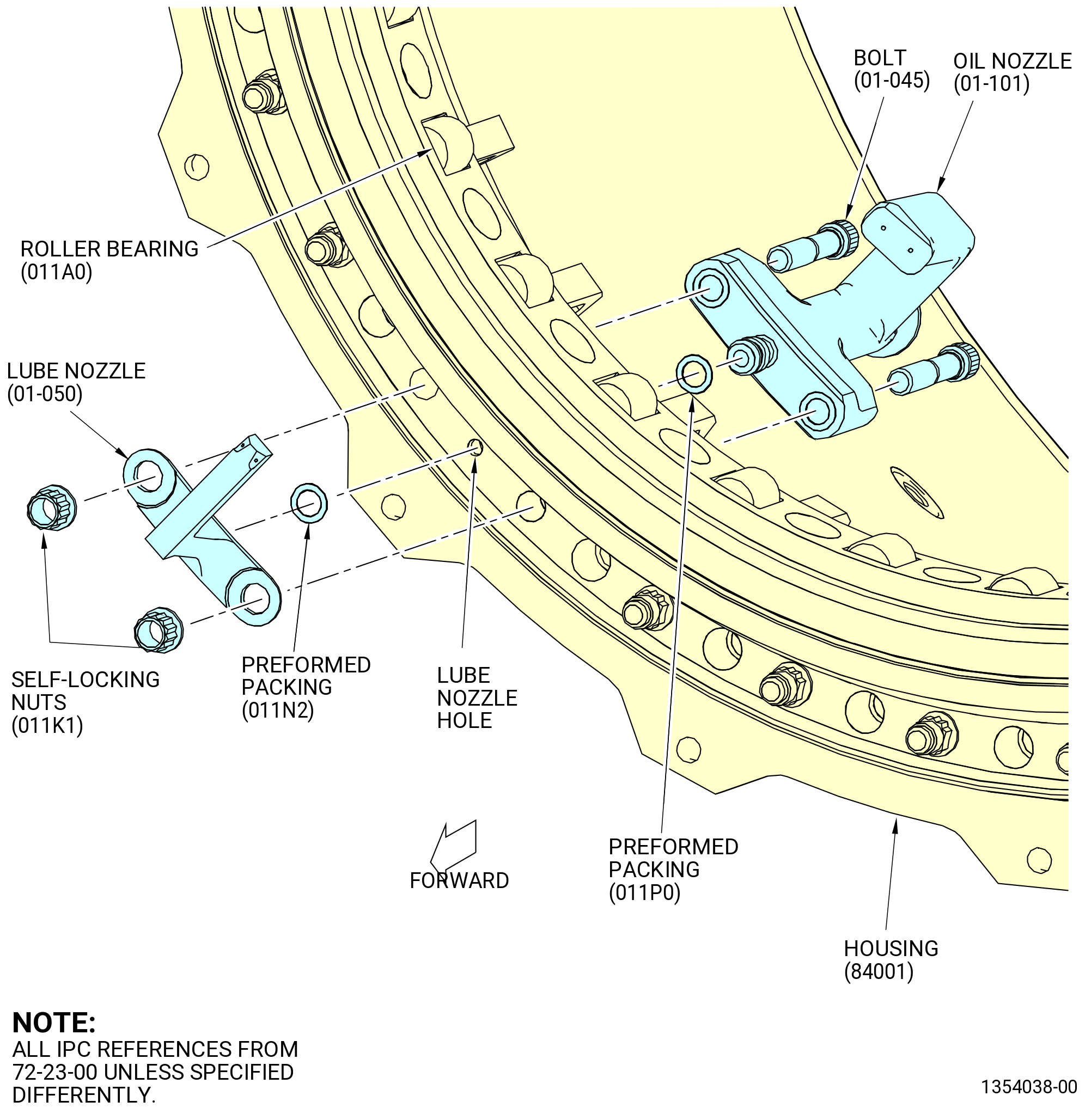
| C.A. | Remove the oil nozzle (01-101) and lube nozzle (01-050) from the housing (84001) as follows. Refer to Figure 508. |
| (1) | Loosen and remove the self-locking nuts (011K1) from the bolts (01-045). |
| (2) | Remove the lube nozzle from the housing. |
| (3) | Remove and discard the preformed packing (01-060) (SIN 011N2) from the groove on the lube nozzle. |
| (4) | Remove the bolts (01-045) and oil nozzle from the housing. |
| (5) | Remove and discard the preformed packing (01-090) (SIN 011P0) from the groove on the oil nozzle. |
| * * * END SB 72-0011 |
| Subtask 72-23-00-040-015 |
| (6) | Remove the self-locking nuts (011K0) and bolts (011F0) that attach the roller bearing (011A0) to the housing. |
|
|
| Subtask 72-23-00-040-012 |
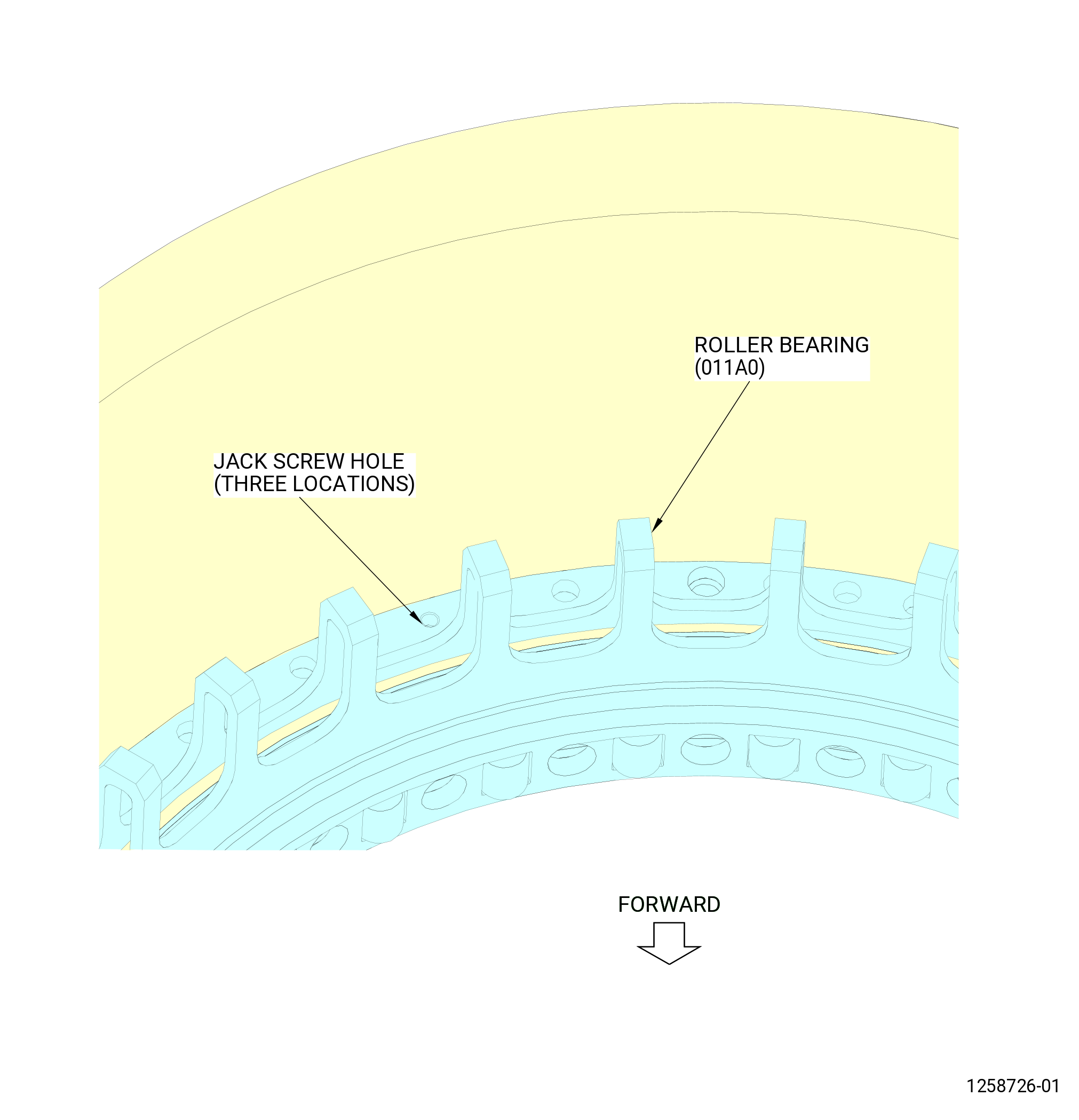
| D. | Remove the roller bearing (011A0) from the housing (84001) as follows. Refer to Figure 509. |
| (1) | Turn the housing in the 9401M62 adjustable stand. Refer to Figure 506 and do as follows: |
| (a) | Move the lever (item 24) to disengage the locating pin from the locating plate (item 6). |
| (b) | Turn the hand wheel (item 13) to level the 9481M78 bracket adapter. |
| CAUTION: |
|
| (c) | Move the lever (item 24) to prevent turning of the locating plate (item 6). |
| (2) | Install three 0.250-28 UNF-3B screws (item 15) (not shown) of the 9429M50 jack screw set in the roller bearing flange jack screw holes. |
| (3) | Turn the screws (item 15) to loosen the roller bearing. |
| (4) | Remove the screws (item 15) from the roller bearing. |
| Subtask 72-23-00-040-011 |
| CAUTION: |
|
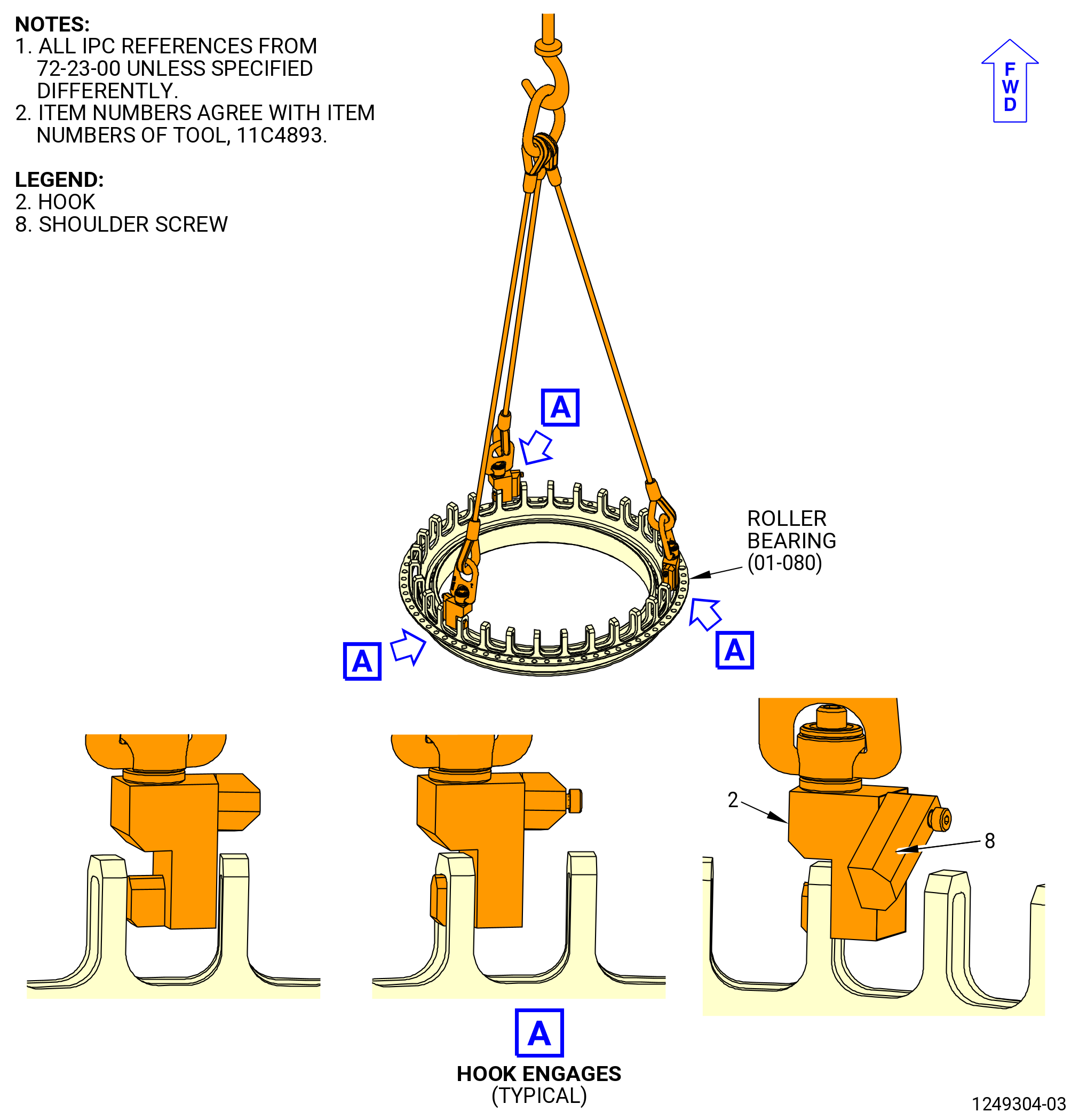
| E. | Put the roller bearing (011A0) in storage as follows: |
| (1) | Attach an overhead hoist to the 11C4893 lifting tool. Refer to Figure 510. |
| WARNING: |
|
| (2) | Lower the 11C4893 lifting tool to the roller bearing. |
| (3) | Swing the shoulder screw (item 8) into a horizontal position, and then slide the hook (item 2) into the roller bearing cage assembly. |
| (4) | Permit the shoulder screw (item 8) to swing back to vertical to attach firmly the hook (item 2). |
| (5) | Repeat step (3) and step (4) for the remaining two hooks. Space hooks 10 places apart to achieve approximately 120 degrees space between of legs. |
| (6) | Lift the roller bearing and put it on a clean work surface. |
| (7) | Remove the 11C4893 lifting tool from the roller bearing. |
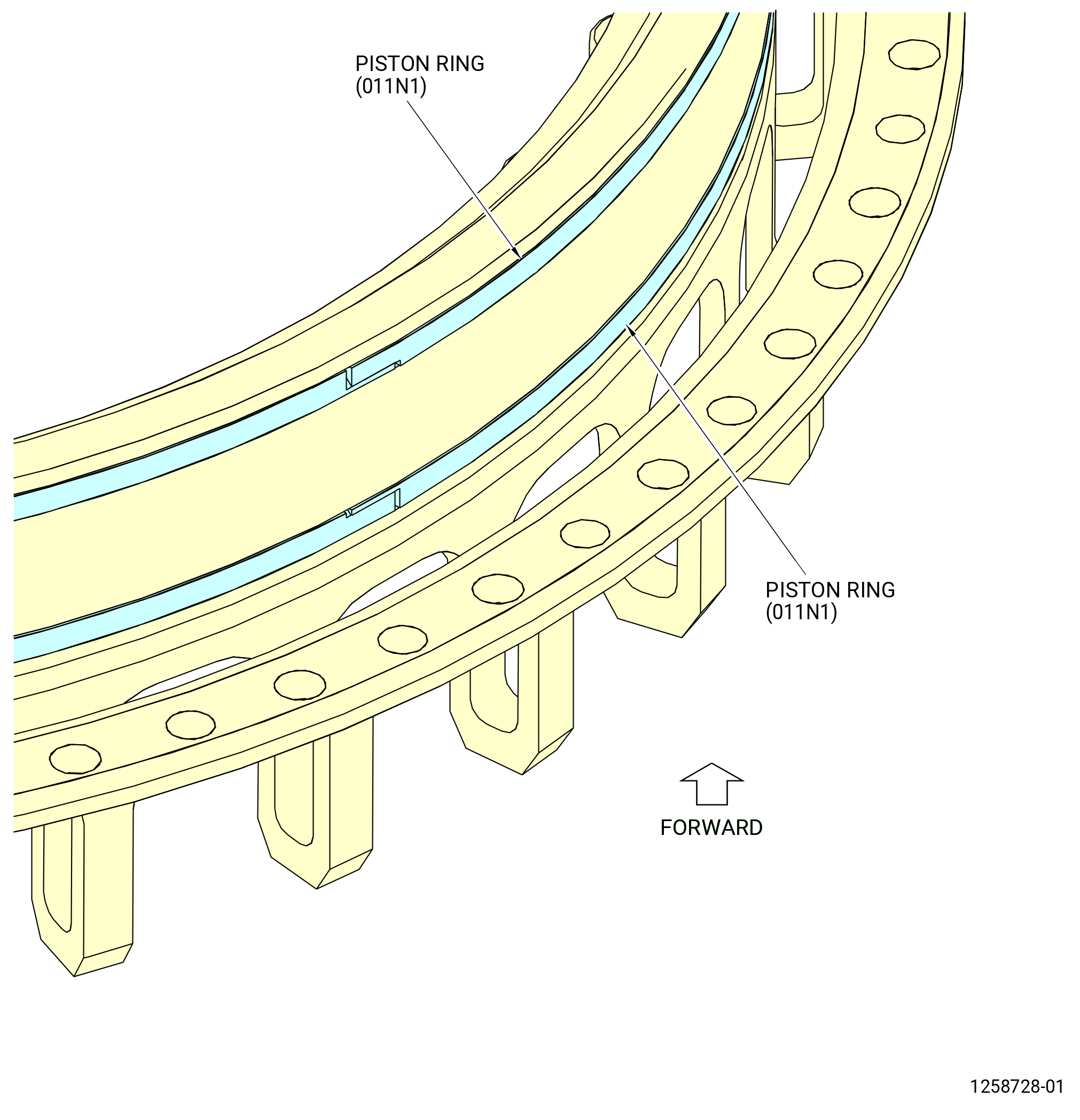
| (8) | Turn the roller bearing to the forward end up position. |
| (9) | Remove the two piston rings (011N1) from the roller bearing. Refer to Figure 511. |
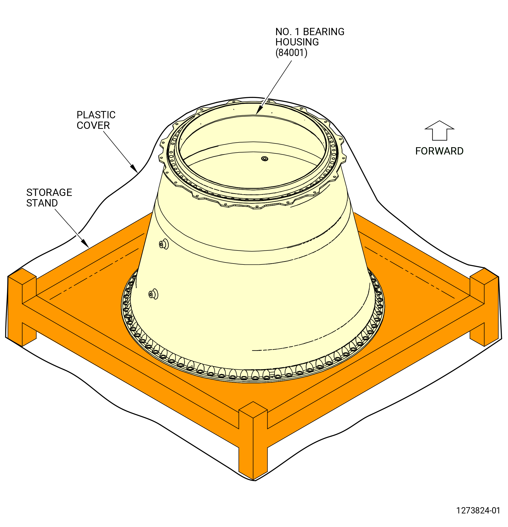
| (10) | Put the roller bearing in a storage container or in a safe location and cover it. |
| Subtask 72-23-00-040-004 |
| F. | Put the housing (84001) in storage as follows: |
| (1) | Adjust the trunnions (item 12) of the 11C3151 lift and turn fixture to the scribe line marked WITHOUT BEARING on each support (item 2 and item 3). Refer to Figure 504. |
| (2) | Attach the 9429M77 lift/turn fixture as follows. Refer to Figure 503: |
| WARNING: |
|
| (a) | Attach the assembly hoist (item 24) to the lift bar (item 23), with the forged anchor shackles (item 27) of the 9429M77 lift/turn fixture, to the same quantity of holes on the right and left side to keep the tool balanced. Make sure that the assembly hoists (item 24) are perpendicular (at the right angle) to the lift bar (item 23) after connecting the 9429M77 lift/turn fixture to the 11C3151 lift and turn fixture. |
| (b) | Attach each lock plate adapter (item 13) of the 9429M77 lift/turn fixture from each assembly hoist (item 24) with the forged anchor shackle (item 27). |
| (c) | Push the latch (item 14) to let the lock plate adapter (item 13) to attach to each trunnion (item 12) of the 11C3151 lift and turn fixture. |
| (d) | Make sure the latch (item 14) of the 9429M77 lift/turn fixture engages the trunnions (item 12) of the 11C3151 lift and turn fixture and put the release pin (item 19) of the 9429M77 lift/turn fixture through the trunnions (item 12) of the 11C3151 lift and turn fixture and the lock plate adapter (item 13) of the 9429M77 lift/turn fixture. |
| (3) | Remove the ball-lock pin of the 9481M78 bracket adapter to release the trunnions (item 8) of the 11C3151 lift and turn fixture. |
| (4) | Use the 9429M77 lift/turn fixture to lift the housing from the 9401M62 adjustable stand. |
| WARNING: |
|
| (5) | Use a hoist and the 9429M77 lift/turn fixture to lift the housing from the 9401M62 adjustable stand. |
| (6) | Put the housing in a container or in a safe location and cover it. Refer to Figure 512. |
| (7) | Remove the 9429M77lift/turn fixture from the 11C3151 lift and turn fixture. |
| Subtask 72-23-00-040-009 |
| G. | Remove the 11C3151 lift and turn fixture as follows. Refer to Figure 504. |
| (1) | Loosen the thumb screws (item 4) to retract the spring pins (item 10) that extend into the boltholes in the aft flange of the housing. |
| (2) | Remove the right support (item 2) and left support (item 3). |