| GENX-1B ENGINE MANUAL | Dated: 10/05/2023 | |
| EM 72-32-00 , DISASSEMBLY 001 | ||
| HIGH PRESSURE COMPRESSOR FORWARD STATOR ASSEMBLY - DISASSEMBLY 001 | ||
| GENX-1B ENGINE MANUAL | Dated: 10/05/2023 | |
| EM 72-32-00 , DISASSEMBLY 001 | ||
| HIGH PRESSURE COMPRESSOR FORWARD STATOR ASSEMBLY - DISASSEMBLY 001 | ||
| * * * FOR ALL |
| TASK 72-32-00-040-801 |
| 1 . | General. |
| A. | This procedure gives instructions to disassemble the high pressure compressor (HPC) forward stator assembly (forward stator assembly). Refer to Figure 501. |
| • |
|
| • |
|
| B. | This procedure starts with the upper or lower compressor stator forward case (case) half (15-010) or (15-011) (SIN 073A0) installed, forward end down, on the 11C3301 adapter stand. Refer to Figure 502. |
| 2 . | Tools, Equipment, and Materials. |
| NOTE: |
|
| A. | Tools and Equipment. |
| (1) | Special Tools. |
| (2) | Standard Tools and Equipment. None. |
| (3) | Locally Manufactured Tools. None. |
| B. | Consumable Materials. None. |
| C. | Referenced Procedures. None. |
| D. | Expendable Parts. None. |
|
|
| 3 . | Procedure. |
| Subtask 72-32-00-040-022 |
| A. | Disassemble the upper and lower case half assemblies (15-010) or (15-011) (SIN 073A0) as follows. Refer to Figure 503 and Figure 504. |
| NOTE: |
|
| (1) | Remove the VSV actuator supports (05-050) (SIN 075C0) and bolts (05-060) (SIN 075F3). |
| (2) | On the upper case half assembly only, remove the stages 2-5 borescope plugs (05-010) (SIN 075AK), (05-020) (SIN 075AL), (05-030) (SIN 075AM) and (05-040) (SIN 075AB). |
| (3) | Use a nylon bar and a mallet to carefully remove the stage 4 aft covers (15-020) (SIN 070AG), (15-030) (SIN 070AR), (15-040) (SIN 070AJ) and (15-050) (SIN 070AS) or (15-021) (SIN 070AG) and (15-041) (SIN 070AJ) or (15-021) (SIN 070AG), (15-041) (SIN 070AJ), (15-030) (SIN 070AR), and (15-050) (SIN 070AS) or (15-030) (SIN 070AR), (15-021) (SIN 070AG), (15-040) (SIN 070AJ), and (15-050) (SIN 070AS). |
| Subtask 72-32-00-040-023 |
| B. | Disassemble the stage 4 upper and lower stator assemblies as follows. Refer to Figure 505. |
| (1) | Remove the stage 4 compressor stator seals (10-200) (SIN 076A4) and (10-210) (SIN 076AD) from the stage 4 stator shrouds (10-180) (SIN 071B4) and (10-190) (SIN 071B9). |
| (2) | Remove the stage 4 stator shrouds (10-180) (SIN 071B4) and (10-190) (SIN 071B9) as follows: |
| (a) | Remove the nuts (10-030) (SIN 071K2) and the bolts (10-020) (SIN 071F1) from the stage 4 stator shrouds. Discard the nuts and bolts. |
| (b) | Remove the stage 4 stator shrouds from the case half assembly. You must keep the compressor stator shrouds together as a matched set. |
| NOTE: |
|
| Subtask 72-32-00-040-024 |
| (3) | Alternative Procedure Available. Remove the first two stage 4 lever arms (01-170) (SIN 071D9) on each side of the case half (15-010) (SIN 073A0) or (15-011) (SIN 073A0) adjacent to the split line flange as follows: |
| (a) | Install the tool 11C4653 installation tool or 11C4657 installation tool on stage 4 VSV vanes (10-169) (SIN 072A4) or (10-170) (SIN 072A4) or (10-171) (SIN 072A4) or (10-172) (SIN 072A4). Starting from the left when facing the inside of a stator half-case, slide the stage 1-4 over the first several vanes. Refer to Figure 506 and Figure 507. |
| WARNING: |
|
| (b) | Repeat this procedure for the remaining sections of stage 4 vanes. |
| (c) | Remove the nuts (01-010) (SIN 071K0) that attach the lever arm (01-170) (SIN 071D9). |
| Subtask 72-32-00-040-025 |
| * * * FOR 1B/P/G03.1B/P/G04.1B/P1/G01 |
| * * * PRE SB 72-0052( Initial VSV Lever Arm System ) |
| (d) | Remove the lever arm (01-170) (SIN 071D9). |
| * * * END PRE SB 72-0052( ) |
| Subtask 72-32-00-040-026 |
| * * * FOR ALL |
| * * * SB 72-0052( Simplified VSV Lever Arm System ) |
| (d).A. | Remove the lever arm (01-170) (SIN 071D9) and sleeve (01-200) (SIN 071T4). Discard the sleeve. |
| NOTE: |
|
| * * * END SB 72-0052 |
| Subtask 72-32-00-040-027 |
| (e) | Deleted. |
| Subtask 72-32-00-040-053 |
| (6).A. | Alternative Procedure. Remove the first two stage 4 lever arms (01-170) (SIN 071D9) on each side of the case half (15-010) (SIN 073A0) or (15-011) (SIN 073A0) adjacent to the split line flange. Refer to Figure 504 and Figure 508, and do as follows: |
| (a) | Install the stage 2-4 stator vane holder (item 17) of the 11C3305 countertorque tool on the first stage 4 VSV (10-169) (SIN 072A4) or (10-170) (SIN 072A4) or (10-171) (SIN 072A4) or (10-172) (SIN 072A4) at the split line flange. |
| (b) | Use the stage 2-4 stator vane holder (item 17) to hold the stage 4 VSV while removing the nut (01-010) (SIN 071K0) that attaches the lever arm (01-170) (SIN 071D9). |
| Subtask 72-32-00-040-054 |
| * * * FOR 1B/P/G03.1B/P/G04.1B/P1/G01 |
| * * * PRE SB 72-0052( Initial VSV Lever Arm System ) |
| (c) | Remove the lever arm (01-170) (SIN 071D9). |
| * * * END PRE SB 72-0052 |
| Subtask 72-32-00-040-055 |
| * * * FOR ALL |
| * * * SB 72-0052( Simplified VSV Lever Arm System ) |
| (c).A. | Remove the lever arm (01-170) (SIN 071D9) and sleeve (01-200) (SIN 071T4). Discard the sleeve. |
| NOTE: |
|
| * * * END SB 72-0052 |
| Subtask 72-32-00-040-056 |
| (d) | Remove the stage 4 VSV (10-169) (SIN 072A4) or (10-170) (SIN 072A4) or (10-171) (SIN 072A4) or (10-172) (SIN 072A4). |
| Subtask 72-32-00-040-028 |
| (7) | Alternative Procedure Available. Remove the remaining stage 4 lever arms (01-160) (SIN 071D4) and (01-180) (SIN 071C0) from the case half (15-010) (SIN 073A0) or (15-011) (SIN 073A0) as follows: |
| (a) | Remove the nuts (01-010) (SIN 071K0) that attach the lever arms (01-160) (SIN 071D4) and (01-180) (SIN 071C0) while the tool 11C4653 installation tool or 11C4657 installation tool is installed on stage 4 vanes. |
| Subtask 72-32-00-040-029 |
| * * * FOR 1B/P/G03.1B/P/G04.1B/P1/G01 |
| * * * PRE SB 72-0052( Initial VSV Lever Arm System ) |
| (b) | Remove the lever arms (01-160) (SIN 071D4) and (01-180) (SIN 071C0) from the stage 4 ring segments (01-140) (SIN 071A4), (01-150) (SIN 071A9), and the stage 4 VSV (10-169) (SIN 072A4) or (10-170) (SIN 072A4). |
| * * * END PRE SB 72-0052 |
| Subtask 72-32-00-040-030 |
| * * * SB 72-0052( Simplified VSV Lever Arm System ) |
| * * * PRE SB 72-0158( High Pressure Compressor Stator Assembly - PIP Configuration ) |
| (b).A. | Remove the lever arms (01-160) (SIN 071D4) and (01-180) (SIN 071C0) and sleeves (01-200) (SIN 071T4) from the stage 4 ring segments (01-140) (SIN 071A4), (01-150) (SIN 071A9), and the stage 4 VSV (10-171) (SIN 072A4). Discard the sleeves. |
| NOTE: |
|
| * * * END SB 72-0052 |
| * * * END PRE SB 72-0158 |
| Subtask 72-32-00-040-050 |
| * * * FOR ALL PIP 2 |
| * * * SB 72-0158( High Pressure Compressor Stator Assembly - PIP2 Configuration ) |
| (b).B. | Remove the lever arms (01-160) (SIN 071D4) or (01-180) (071C0) and sleeves (01-200) (SIN 071T4) from the stage 4 ring segments (01-140) (SIN 071A4) and (01-150) (SIN 071A9) and stage 4 VSV (10-172) (SIN 072A4). Discard the sleeves. |
| * * * END SB 72-0158 |
| Subtask 72-32-00-040-010 |
| * * * FOR ALL |
| (c) | Remove the stage 4 VSV (10-169) (SIN 072A4) or (10-170) (SIN 072A4) or (10-171) (SIN 072A4) or (10-172) (SIN 072A4). |
| (d) | Remove the stage 4 ring segments (01-140) (SIN 071A4), (01-150) (SIN 071A9). |
| Subtask 72-32-00-040-057 |
| (12).A. | Alternative Procedure. Remove the remaining stage 4 lever arms (01-160) (SIN 071D4) and (01-180) (SIN 071C0) from the case half (15-010) (SIN 073A0) or (15-011) (SIN 073A0) as follows: |
| (a) | Install the upper stage 4 sector (item 5) or the lower stage 4 sector (item 13) of the 11C3305 countertorque tool on each side of the stage 4 actuating rings (ring segments) (01-140) (SIN 071A4), (01-150) (SIN 071A9) at the flange split line until the block (item 6) touches the case half. |
| (b) | Install the two threaded screws (item 7) of each stage 4 sectors (items 5, 13) into the stage 4 ring segments (01-140) (SIN 071A4), (01-150) (SIN 071A9). |
| (c) | Hand tighten the threaded screws (item 7). |
| (d) | Remove the nuts (01-010) (SIN 071K0) that attach the lever arms (01-160) (SIN 071D4) and (01-180) (SIN 071C0). |
| Subtask 72-32-00-040-058 |
| * * * FOR 1B/P/G03.1B/P/G04.1B/P1/G01 |
| * * * PRE SB 72-0052( Initial VSV Lever Arm System ) |
| (e) | Remove the lever arms (01-160) (SIN 071D4) and (01-180) (SIN 071C0) from the stage 4 ring segments (01-140) (SIN 071A4), (01-150) (SIN 071A9), and the stage 4 VSV (10-169) (SIN 072A4) or (10-170) (SIN 072A4). |
| * * * END PRE SB 72-0052 |
| Subtask 72-32-00-040-059 |
| * * * FOR ALL |
| * * * SB 72-0052( Simplified VSV Lever Arm System ) |
| * * * PRE SB 72-0158( High Pressure Compressor Stator Assembly - PIP Configuration ) |
| (e).A. | Remove the lever arms (01-160) (SIN 071D4) and (01-180) (SIN 071C0) and sleeves (01-200) (SIN 071T4) from the stage 4 ring segments (01-140) (SIN 071A4), (01-150) (SIN 071A9), and the stage 4 VSV (10-171) (SIN 072A4). Discard the sleeves. |
| NOTE: |
|
| * * * END SB 72-0052 |
| * * * END PRE SB 72-0158 |
| Subtask 72-32-00-040-060 |
| * * * FOR ALL PIP 2 |
| * * * SB 72-0158( High Pressure Compressor Stator Assembly - PIP 2 Configuration ) |
| (e).B. | Remove the lever arms (01-160) (SIN 071D4) and (01-180) (SIN 071C0) and sleeves (01-200) (SIN 071T4) from the stage 4 ring segments (01-140) (SIN 071A4) and (01-150) (SIN 071A9) and stage 4 VSV (10-172) (SIN 072A4). Discard the sleeves. |
| * * * END SB 72-0158 |
| Subtask 72-32-00-040-061 |
| * * * FOR ALL |
| (f) | Remove the stage 4 VSV (10-169) (SIN 072A4) or (10-170) (SIN 072A4) or (10-171) (SIN 072A4) or (10-172) (SIN 072A4). |
| (g) | Remove the stage 4 ring segments (01-140) (SIN 071A4), (01-150) (SIN 071A9). |
|
|
|
|
|
|
|
| Subtask 72-32-00-040-012 |
| C. | Disassemble the stage 3 upper and lower stator assemblies as follows. Refer to Figure 505 and Figure 508. |
| (1) | Remove the stage 3 stator seals (10-150) (SIN 076A3) and (10-160) (SIN 076AC) from the stage 3 vane shrouds (10-140) (SIN 071B3). |
| (2) | Remove the stage 3 vane shrouds (10-140) (SIN 071B3) as follows: |
| (a) | Remove the nuts (10-030) (SIN 071K2) and the bolts (10-020) (SIN 071F1) from the stage 3 vane shrouds. Discard the nuts and bolts. |
| (b) | Remove the stage 3 vane shrouds from the case half (15-010) or (15-011) (SIN 073A0). The stage 3 vane shrouds must be kept together as a matched set. |
| Subtask 72-32-00-040-031 |
| (3) | Alternative Procedure Available. Remove the first two stage 3 lever arms (01-130) (SIN 071D8) on each side of the case half (15-010) (SIN 073A0) or (15-011) (SIN 073A0) adjacent to the split line flange as follows: |
| (a) | Refer to Subtask 72-32-00-040-024 (paragraph 3.B.(3)) to install the 11C4653 installation tool or 11C4657 installation tool for stage 3. |
| (b) | Remove the nut (01-010) (SIN 071K0) that attach the lever arm (01-130) (SIN 071D8). |
| Subtask 72-32-00-040-032 |
| * * * FOR 1B/P/G03.1B/P/G04.1B/P1/G01 |
| * * * PRE SB 72-0052( Initial VSV Lever Arm System ) |
| (c) | Remove the lever arm (01-130) (SIN 071D8). |
| * * * END PRE SB 72-0052 |
| Subtask 72-32-00-040-033 |
| * * * SB 72-0052( Simplified VSV Lever Arm System ) |
| (c).A. | Remove the lever arm (01-130) (SIN 071D8) and sleeve (01-190) (SIN 071T3). Discard the sleeve. |
| NOTE: |
|
| * * * END SB 72-0052( ) |
| Subtask 72-32-00-040-013 |
| (d) | Deleted. |
| Subtask 72-32-00-040-062 |
| * * * FOR ALL |
| (6).A. | Alternative Procedure. Remove the first two stage 3 lever arms (01-130) (SIN 071D8) on each side of the case half (15-010) (SIN 073A0) or (15-011) (SIN 073A0) adjacent to the split line flange. Refer to Figure 504, Figure 508, and do as follows: |
| (a) | Install the stage 2-4 stator vane holder (item 17) of the 11C3305 countertorque tool on the first stage 3 VSV (10-129) (SIN 072A3) or (10-130) (SIN 072A3) or (10-131) (SIN 072A3) at the split line flange. |
| (b) | Use the stage 2-4 stator vane holder (item 17) to hold the stage 3 VSV while removing the nut (01-010) (SIN 071K0) that attach the lever arm (01-130) (SIN 071D8). |
| Subtask 72-32-00-040-063 |
| * * * FOR 1B/P/G03.1B/P/G04.1B/P1/G01 |
| * * * PRE SB 72-0052( Initial VSV Lever Arm System ) |
| (c) | Remove the lever arm (01-130) (SIN 071D8). |
| * * * END PRE SB 72-0052 |
| Subtask 72-32-00-040-064 |
| * * * FOR 1B/P/G03.1B/P/G04.1B/P1/G01 |
| * * * SB 72-0052( Simplified VSV Lever Arm System ) |
| (c).A. | Remove the lever arm (01-130) (SIN 071D8) and sleeve (01-190) (SIN 071T3). Discard the sleeve. |
| NOTE: |
|
| * * * END SB 72-0052 |
| Subtask 72-32-00-040-065 |
| * * * FOR ALL |
| (d) | Remove the stage 3 VSV (10-129) (SIN 072A3) or (10-130) (SIN 072A3) or (10-131) (SIN 072A3). |
| Subtask 72-32-00-040-066 |
| (7) | Alternative Procedure Available. Remove the remaining stage 3 lever arms (01-120) (SIN 071D3) and (01-180) (SIN 071C0) from the case half (15-010) (SIN 073A0) or (15-011) (SIN 073A0) as follows: |
| (a) | Remove the nuts (01-010) (SIN 071K0) that attach the lever arms (01-120) (SIN 071D3) and (01-180) (SIN 071C0) while the 11C4653 installation tool or 11C4657 installation tool is installed on the stage 3 vanes. |
| Subtask 72-32-00-040-034 |
| * * * FOR 1B/P/G03.1B/P/G04.1B/P1/G01 |
| * * * PRE SB 72-0052( Initial VSV Lever Arm System ) |
| (b) | Remove the stage 3 lever arms (01-120) (SIN 071D3) and (01-180) (SIN 071C0) from the stage 3 ring segments (01-110) (SIN 071A3) and the stage 3 VSV (10-129) (SIN 072A3) or (10-130) (SIN 072A3). |
| * * * END PRE SB 72-0052 |
| Subtask 72-32-00-040-035 |
| * * * FOR 1B/P/G03.1B/P/G04.1B/P1/G01 |
| * * * SB 72-0052( Simplified VSV Lever Arm System ) |
| (b).A. | Remove the stage 3 lever arms (01-120) (SIN 071D3) and sleeves (01-190) (SIN 071T3) from the stage 3 ring segments (01-110) (SIN 071A3) and the stage 3 VSV (10-131) (SIN 072A3). Discard the sleeves. |
| NOTE: |
|
| * * * END SB 72-0052 |
| Subtask 72-32-00-040-036 |
| * * * FOR ALL |
| (c) | Remove the stage 3 VSV (10-129) (SIN 072A3) or (10-130) (SIN 072A3) or (10-131) (SIN 072A3). |
| (d) | Remove the stage 3 ring segments (01-110) (SIN 071A3). |
| Subtask 72-32-00-040-068 |
| (7).E. | Alternative Procedure. Remove the remaining stage 3 lever arms (01-120) (SIN 071D3) and (01-180) (SIN 071C0) from the case half (15-010) (SIN 073A0) or (15-011) (SIN 073A0). Refer to Figure 504, Figure 508, and do as follows: |
| (a) | Install the stage 3 sectors (item 4) of the 11C3305 countertorque tool on each side of the stage 3 ring segments (01-110) (SIN 071A3) at the flange split line until the block (item 6) touches the case half. |
| (b) | Install the two threaded screws (item 7) of each stage 3 sectors (item 4) into the stage 3 ring segments (01-110) (SIN 071A3). |
| (c) | Hand tighten the threaded screws (item 7). |
| (d) | Remove the nuts (01-010) (SIN 071K0) that attach the lever arms (01-120) (SIN 071D3) and (01-180) (SIN 071C0). |
| Subtask 72-32-00-040-069 |
| * * * FOR 1B/P/G03.1B/P/G04.1B/P1/G01 |
| * * * PRE SB 72-0052( Initial VSV Lever Arm System ) |
| (e) | Remove the stage 3 lever arms (01-120) (SIN 071D3) and (01-180) (SIN 071C0) from the stage 3 ring segments (01-110) (SIN 071A3) and the stage 3 VSV (10-129) (SIN 072A3) or (10-130) (SIN 072A3). |
| * * * END PRE SB 72-0052 |
| Subtask 72-32-00-040-070 |
| * * * FOR 1B/P/G03.1B/P/G04.1B/P1/G01 |
| * * * SB 72-0052( Simplified VSV Lever Arm System ) |
| (e).A. | Remove the stage 3 lever arms (01-120) (SIN 071D3) and sleeves (01-190) (SIN 071T3) from the stage 3 ring segments (01-110) (SIN 071A3) and the stage 3 VSV (10-131) (SIN 072A3). Discard the sleeves. |
| NOTE: |
|
| * * * END SB 72-0052 |
| Subtask 72-32-00-040-072 |
| * * * FOR ALL |
| (f) | Remove the stage 3 VSV (10-129) (SIN 072A3) or (10-130) (SIN 072A3) or (10-131) (SIN 072A3). |
| (g) | Remove the stage 3 ring segments (01-110) (SIN 071A3). |
| Subtask 72-32-00-040-015 |
| D. | Disassemble the stage 2 upper and lower stator assemblies as follows. Refer to Figure 505 and Figure 508. |
| (1) | Remove the stage 2 stator seals (10-110) (SIN 076A2) and (10-120) (SIN 076AB) from the stage 2 vane shrouds (10-100) (SIN 071B2). |
| (2) | Remove the stage 2 vane shrouds as follows: |
| (a) | Remove the nuts (10-030) (SIN 071K2) and the bolts (10-020) (SIN 071F1) from the stage 2 vane shrouds (10-100) (SIN 071B2). Discard the nuts and bolts. |
| (b) | Remove the stage 2 vane shrouds from the case half (15-010) or (15-011) (SIN 073A0). The stage 2 vane shrouds must be kept together as a matched set. |
| Subtask 72-32-00-040-037 |
| (3) | Alternative Procedure Available. Remove the first two stage 2 lever arms (01-100) (SIN 071D7) on each side of the case half (15-010) (SIN 073A0) or (15-011) (SIN 073A0) adjacent to the split line flange as follows: |
| (a) | Refer to Subtask 72-32-00-040-024 (paragraph 3.B.(3)) to install the 11C4653 installation tool or 11C4657 installation tool on stage 2 vanes. |
| (b) | Remove the nut (01-010) (SIN 071K0) that attach the lever arm (01-100) (SIN 071D7). |
| Subtask 72-32-00-040-038 |
| * * * FOR 1B/P/G03 |
| * * * PRE SB 72-0052( Initial VSV Lever Arm System ) |
| (c) | Remove the lever arm (01-100) (SIN 071D7). |
| * * * END PRE SB 72-0052 |
| Subtask 72-32-00-040-039 |
| * * * FOR ALL |
| * * * SB 72-0052( Simplified VSV Lever Arm System ) |
| (c).A. | Remove the lever arm (01-100) (SIN 071D7) and sleeve (01-190) (SIN 071T3). Discard the sleeve. |
| NOTE: |
|
| * * * END SB 72-0052 |
| Subtask 72-32-00-040-082 |
| (d) | Deleted. |
| Subtask 72-32-00-040-083 |
| (6).A. | Alternative Procedure. Remove the first two stage 2 lever arms (01-100) (SIN 071D7) on each side of the case half (15-010) (SIN 073A0) or (15-011) (SIN 073A0) adjacent to the split line flange as follows: |
| (a) | Install the stage 2-4 stator vane holder (item 17) of the 11C3305 countertorque tool on the first stage 2 VSV (10-089) (SIN 072A2) or (10-090) (SIN 072A2) or (10-091) (SIN 072A2) or (10-092) (SIN 072A2) at the split line flange. |
| (b) | Use the stage 2-4 stator vane holder (item 17) to hold the stage 2 VSV while removing the nut (01-010) (SIN 071K0) that attach the lever arm (01-100) (SIN 071D7). |
| Subtask 72-32-00-040-084 |
| * * * FOR 1B/P/G03 |
| * * * PRE SB 72-0052( Initial VSV Lever Arm System ) |
| (c) | Remove the lever arm (01-100) (SIN 071D7). |
| * * * END PRE SB 72-0052 |
| Subtask 72-32-00-040-085 |
| * * * FOR ALL |
| * * * SB 72-0052( Simplified VSV Lever Arm System ) |
| (c).A. | Remove the lever arm (01-100) (SIN 071D7) and sleeve (01-190) (SIN 071T3). Discard the sleeve. |
| NOTE: |
|
| * * * END SB 72-0052 |
| Subtask 72-32-00-040-016 |
| (d) | Remove the stage 2 VSV (10-089) (SIN 072A2) or (10-090) (SIN 072A2) or (10-091) (SIN 072A2) or (10-092) (SIN 072A2). |
| Subtask 72-32-00-040-086 |
| (7) | Alternative Procedure Available. Remove the remaining lever arms (01-090) (SIN 071D2) and (01-180) (SIN 071C0) from the case half (15-010) (SIN 073A0) or (15-011) (SIN 073A0) as follows: |
| (a) | Remove the nuts (01-010) (SIN 071K0) that attach the lever arms (01-090) (SIN 071D2) and (01-180) (SIN 071C0) while the 11C4653 installation tool or 11C4657 installation tool is installed on stage 2 vanes. |
| Subtask 72-32-00-040-040 |
| * * * FOR 1B/P/G03.1B/P/G04.1B/P1/G01 |
| * * * PRE SB 72-0052( Initial VSV Lever Arm System ) |
| (b) | Remove the lever arms (01-090) (SIN 071D2) and (01-180) (SIN 071C0) from the stage 2 ring segments (01-080) (SIN 071A2) and the stage 2 VSV (10-089) (SIN 072A2) or (10-090) (SIN 072A2). |
| * * * END PRE SB 72-0052 |
| Subtask 72-32-00-040-041 |
| * * * FOR 1B/P/G03.1B/P/G04.1B/P1/G01 |
| * * * SB 72-0052( Simplified VSV Lever Arm System ) |
| * * * PRE SB 72-0158( High Pressure Compressor Stator Assembly - PIP Configuration ) |
| (b).A. | Remove the lever arms (01-090) (SIN 071D2) and (01-180) (SIN 071C0) and sleeves (01-190) (SIN 071T3) from the stage 2 ring segments (01-080) (SIN 071A2) and the stage 2 VSV (10-091) (SIN 072A2). Discard the sleeves. |
| NOTE: |
|
| * * * END SB 72-0052 |
| * * * END PRE SB 72-0158 |
| Subtask 72-32-00-040-051 |
| * * * FOR ALL PIP 2 |
| * * * SB 72-0158( High Pressure Compressor Stator Assembly - PIP2 Configuration ) |
| (b).B. | Remove the lever arms (01-090) (SIN 071D2) and (01-180) (SIN 071C0) and sleeves (01-190) (SIN 071T3) from the stage 2 ring segments (01-080) (SIN 071A2) and stage 2 VSV (10-092) (SIN 072A2). Discard the sleeves. |
| * * * END SB 72-0158 |
| Subtask 72-32-00-040-042 |
| * * * FOR ALL |
| (c) | Remove the stage 2 VSV (10-089) (SIN 072A2) or (10-090) (SIN 072A2) or (10-091) (SIN 072A2) or (10-092) (SIN 072A2). |
| (d) | Remove the stage 2 ring segments (01-080) (SIN 071A2). |
| Subtask 72-32-00-040-087 |
| (4).A. | Alternative Procedure. Remove the remaining lever arms (01-090) (SIN 071D2) and (01-180) (SIN 071C0) from the case half (15-010) (SIN 073A0) or (15-011) (SIN 073A0) as follows: |
| (a) | Install the stage 2 sectors (item 3) of the 11C3305 countertorque tool on each side of the stage 2 ring segments (01-080) (SIN 071A2) at the flange split line until the block (item 6) touches the case half. |
| (b) | Install the two threaded screws (item 7) of each stage 2 sectors (item 3) into the stage 2 ring segments (01-080) (SIN 071A2). |
| (c) | Hand tighten the threaded screws (item 7). |
| (d) | Remove the nuts (01-010) (SIN 071K0) that attach the lever arms (01-090) (SIN 071D2) and (01-180) (SIN 071C0). |
| Subtask 72-32-00-040-088 |
| * * * FOR 1B/P/G03.1B/P/G04.1B/P1/G01 |
| * * * PRE SB 72-0052( Initial VSV Lever Arm System ) |
| (e) | Remove the lever arms (01-090) (SIN 071D2) and (01-180) (SIN 071C0) from the stage 2 ring segments (01-080) (SIN 071A2) and the stage 2 VSV (10-089) (SIN 072A2) or (10-090) (SIN 072A2). |
| * * * END PRE SB 72-0052 |
| Subtask 72-32-00-040-089 |
| * * * FOR 1B/P/G03.1B/P/G04.1B/P1/G01 |
| * * * SB 72-0052( Simplified VSV Lever Arm System ) |
| * * * PRE SB 72-0158( High Pressure Compressor Stator Assembly - PIP Configuration ) |
| (e).A. | Remove the lever arms (01-090) (SIN 071D2) and (01-180) (SIN 071C0) and sleeves (01-190) (SIN 071T3) from the stage 2 ring segments (01-080) (SIN 071A2) and the stage 2 VSV (10-091) (SIN 072A2). Discard the sleeves. |
| NOTE: |
|
| * * * END SB 72-0052 |
| * * * END PRE SB 72-0158 |
| Subtask 72-32-00-040-090 |
| * * * FOR ALL PIP 2 |
| * * * SB 72-0158( High Pressure Compressor Stator Assembly - PIP2 Configuration ) |
| (e).B. | Remove the lever arms (01-090) (SIN 071D2) and (01-180) (SIN 071C0) and sleeves (01-190) (SIN 071T3) from the stage 2 ring segments (01-080) (SIN 071A2) and stage 2 VSV (10-092) (SIN 072A2). Discard the sleeves. |
| * * * END SB 72-0158 |
| Subtask 72-32-00-040-091 |
| * * * FOR ALL |
| (f) | Remove the stage 2 VSV (10-089) (SIN 072A2) or (10-090) (SIN 072A2) or (10-091) (SIN 072A2) or (10-092) (SIN 072A2). |
| (g) | Remove the stage 2 ring segments (01-080) (SIN 071A2). |
| Subtask 72-32-00-040-018 |
| E. | Disassemble the stage 1 upper and lower stator assemblies as follows. Refer to Figure 505 and Figure 508. |
| (1) | Remove the stage 1 stator seals (10-070) (SIN 076A1) and (10-080) (SIN 076AA) from the stage 1 vane shrouds (10-050) (SIN 071B1) and (10-060) (SIN 071B6). |
| (2) | Remove the stage 1 vane shrouds as follows: |
| (a) | Remove the nuts (10-030) (SIN 071K2) and the bolts (10-020) (SIN 071F1) from the stage 1 vane shrouds (10-050) (SIN 071B1) and (10-060) (SIN 071B6). Discard the nuts and bolts. |
| (b) | Remove the stage 1 vane shrouds from the case half (15-010) or (15-011) (SIN 073A0). The stage 1 vane shrouds must be kept together as a matched set. |
| Subtask 72-32-00-040-019 |
| (3) | Alternative Procedure Available. Remove the first two stage 1 lever arms (01-060) (SIN 071D6) with the bushings (01-070) (SIN 071T1) on each side of the case half (15-010) (SIN 073A0) or (15-011) (SIN 073A0) adjacent to the split line flange as follows. Discard the bushings. |
| (a) | Refer to Subtask 72-32-00-040-024 (paragraph 3.B.(3)) to install the 11C4653 installation tool or 11C4657 installation tool on stage 1 vanes. |
| (b) | Remove the nut (01-010) (SIN 071K0) that attach the lever arm (01-060) (SIN 071D6). |
| Subtask 72-32-00-040-046 |
| * * * FOR 1B/P/G03 |
| * * * PRE SB 72-0052( Initial VSV Lever Arm System ) |
| (c) | Remove the stage 1 lever arm (01-060) (SIN 071D6) with the bushings (01-070) (SIN 071T1). Discard the bushings. |
| * * * END PRE SB 72-0052 |
| Subtask 72-32-00-040-047 |
| * * * FOR 1B/P/G03 |
| * * * SB 72-0052( Simplified VSV Lever Arm System ) |
| (c).A. | Remove the stage 1 lever arm (01-060) (SIN 071D6) with the bushings (01-070) (SIN 071T1) and sleeve (01-190) (SIN 071T3). Discard the bushing and sleeve. |
| NOTE: |
|
| * * * END SB 72-0052 |
| Subtask 72-32-00-040-048 |
| * * * FOR 1B/P/G03 |
| (d) | Deleted. |
| Subtask 72-32-00-040-078 |
| * * * FOR ALL |
| (6).A. | Alternative Procedure. Remove the first two stage 1 lever arms (01-060) (SIN 071D6) with the bushings (01-070) (SIN 071T1) on each side of the case half (15-010) (SIN 073A0) or (15-011) (SIN 073A0) adjacent to the split line flange as follows. Discard the bushings. |
| (a) | Install the stator vane holder (item 16) of the 11C3305 countertorque tool on the first stage 1 VSV (10-039) (SIN 072A1) or (10-040) (SIN 072A1) or (10-041) (SIN 072A1) or (10-042) (SIN 072A1) at the split line flange. |
| (b) | Use the stator vane holder (item 16) to hold the stage 1 VSV while removing the nut (01-010) (SIN 071K0) that attach the lever arm (01-060) (SIN 071D6). |
| Subtask 72-32-00-040-079 |
| * * * FOR 1B/P/G03 |
| * * * PRE SB 72-0052( Initial VSV Lever Arm System ) |
| (c) | Remove the stage 1 lever arm (01-060) (SIN 071D6) with the bushings (01-070) (SIN 071T1). Discard the bushings. |
| * * * END PRE SB 72-0052 |
| Subtask 72-32-00-040-080 |
| * * * FOR ALL |
| * * * SB 72-0052( Simplified VSV Lever Arm System ) |
| (c).A. | Remove the stage 1 lever arm (01-060) (SIN 071D6) with the bushings (01-070) (SIN 071T1) and sleeve (01-190) (SIN 071T3). Discard the bushing and sleeve. |
| NOTE: |
|
| * * * END SB 72-0052 |
| Subtask 72-32-00-040-081 |
| (d) | Remove the stage 1 VSV (10-039) (SIN 072A1) or (10-040) (SIN 072A1) or (10-041) (SIN 072A1) or (10-042) (SIN 072A1) and washers (10-010) (SIN 071J1). |
| Subtask 72-32-00-040-049 |
| (10) | Alternative Procedure Available. Remove the remaining stage 1 lever arms (01-050) (SIN 071D1) and (01-180) (SIN 071C0) from the case half (15-010) (SIN 073A0) or (15-011) (SIN 073A0) as follows: |
| (a) | Remove the nuts (01-010) (SIN 071K0) that attach the lever arms (01-050) (SIN 071D1) and (01-180) (SIN 071C0) while the 11C4653 installation tool or 11C4657 installation tool is installed on stage 1 vanes. |
| Subtask 72-32-00-040-043 |
| * * * FOR 1B/P/G03.1B/P/G04.1B/P1/G01 |
| * * * PRE SB 72-0052( Initial VSV Lever Arm System ) |
| (b) | Remove the stage 1 lever arms (01-050) (SIN 071D1) and (01-180) (SIN 071C0) with the bushings (01-070) (SIN 071T1) from the stage 1 ring segments (01-030) (SIN 071A1), (01-040) (SIN 071A6), and the stage 1 VSV (10-039) (SIN 072A1) or (10-040) (SIN 072A1). Discard the bushings. |
| * * * END PRE SB 72-0052 |
| Subtask 72-32-00-040-044 |
| * * * FOR 1B/P/G03.1B/P/G04.1B/P1/G01 |
| * * * SB 72-0052( Simplified VSV Lever Arm System ) |
| * * * PRE SB 72-0158( High Pressure Compressor Stator Assembly - PIP Configuration ) |
| (b).A. | Remove the stage 1 lever arms (01-050) (SIN 071D1) and (01-180) (SIN 071C0) with the bushings (01-070) (SIN 071T1) and sleeves (01-190) (SIN 071T3) from the stage 1 ring segments (01-030) (SIN 071A1), (01-040) (SIN 071A6), and the stage 1 VSV (01-041) (SIN 072A1). Discard the bushings and sleeves. |
| NOTE: |
|
| * * * END SB 72-0052 |
| * * * END PRE SB 72-0158 |
| Subtask 72-32-00-040-052 |
| * * * FOR ALL PIP 2 |
| * * * SB 72-0158( High Pressure Compressor Stator Assembly - PIP2 Configuration ) |
| (b).B. | Remove the stage 1 lever arms (01-090) (SIN 071D2) and (01-180) (SIN 071C0) with the bushings (01-070) (SIN 071T1) and sleeves (01-190) (SIN 071T3) from the stage 1 ring segments (01-030) (SIN 071A1) and (01-040) (SIN 071A6) and stage 1 VSV (10-042) (SIN 072A1). Discard the bushings and sleeves. |
| * * * END SB 72-0158 |
| Subtask 72-32-00-040-045 |
| * * * FOR ALL |
| (c) | Remove the stage 1 VSV (10-039) (SIN 072A1) or (10-040) (SIN 072A1) or (10-041) (SIN 072A1) or (10-042) (SIN 072A1) and discard the washers (10-010) (SIN 071J1). |
| (d) | Remove the stage 1 ring segments (01-030) (SIN 071A1) and (01-040) (SIN 071A6). |
| Subtask 72-32-00-040-073 |
| (16).A. | Alternative Procedure. Remove the remaining stage 1 lever arms (01-050) (SIN 071D1) and (01-180) (SIN 071C0) from the case half (15-010) (SIN 073A0) or (15-011) (SIN 073A0) as follows: |
| (a) | Install the upper stage 1 sector (item 2) or the lower stage 1 sector (item 14) of the 11C3305 countertorque tool on each side of the stage 1 ring segments (01-030) (SIN 071A1) and (01-040) (SIN 071A6) at the flange split line until the block (item 6) touches the case half. |
| (b) | Install the threaded screws (item 7) of each stage 1 sectors (items 2, 14) into the stage 1 ring segments (01-030) (SIN 071A1) and (01-040) (SIN 071A6). |
| (c) | Hand tighten the threaded screws (item 7). |
| (d) | Remove the nuts (01-010) (SIN 071K0) that attach the lever arms (01-050) (SIN 071D1) and (01-180) (SIN 071C0). |
| Subtask 72-32-00-040-074 |
| * * * FOR 1B/P/G03.1B/P/G04.1B/P1/G01 |
| * * * PRE SB 72-0052( Initial VSV Lever Arm System ) |
| (e) | Remove the stage 1 lever arms (01-050) (SIN 071D1) and (01-180) (SIN 071C0) with the bushings (01-070) (SIN 071T1) from the stage 1 ring segments (01-030) (SIN 071A1), (01-040) (SIN 071A6), and the stage 1 VSV (10-039) (SIN 072A1) or (10-040) (SIN 072A1). Discard the bushings. |
| * * * END PRE SB 72-0052 |
| Subtask 72-32-00-040-075 |
| * * * FOR 1B/P/G03.1B/P/G04.1B/P1/G01 |
| * * * SB 72-0052( Simplified VSV Lever Arm System ) |
| * * * PRE SB 72-0158( High Pressure Compressor Stator Assembly - PIP Configuration ) |
| (e).A. | Remove the stage 1 lever arms (01-050) (SIN 071D1) and (01-180) (SIN 071C0) with the bushings (01-070) (SIN 071T1) and sleeves (01-190) (SIN 071T3) from the stage 1 ring segments (01-030) (SIN 071A1), (01-040) (SIN 071A6), and the stage 1 VSV (01-041) (SIN 072A1). Discard the bushings and sleeves. |
| NOTE: |
|
| * * * END SB 72-0052 |
| * * * END PRE SB 72-0158 |
| Subtask 72-32-00-040-076 |
| * * * FOR ALL PIP 2 |
| * * * SB 72-0158( High Pressure Compressor Stator Assembly - PIP2 Configuration ) |
| (e).B. | Remove the stage 1 lever arms (01-090) (SIN 071D2) and (01-180) (SIN 071C0) with the bushings (01-070) (SIN 071T1) and sleeves (01-190) (SIN 071T3) from the stage 1 ring segments (01-030) (SIN 071A1) and (01-040) (SIN 071A6) and stage 1 VSV (10-042) (SIN 072A1). Discard the bushings and sleeves. |
| * * * END SB 72-0158 |
| Subtask 72-32-00-040-077 |
| * * * FOR ALL |
| (f) | Remove the stage 1 VSV (10-039) (SIN 072A1) or (10-040) (SIN 072A1) or (10-041) (SIN 072A1) or (10-042) (SIN 072A1) and discard the washers (10-010) (SIN 071J1). |
| (g) | Remove the stage 1 ring segments (01-030) (SIN 071A1) and (01-040) (SIN 071A6). |
| Subtask 72-32-00-040-021 |
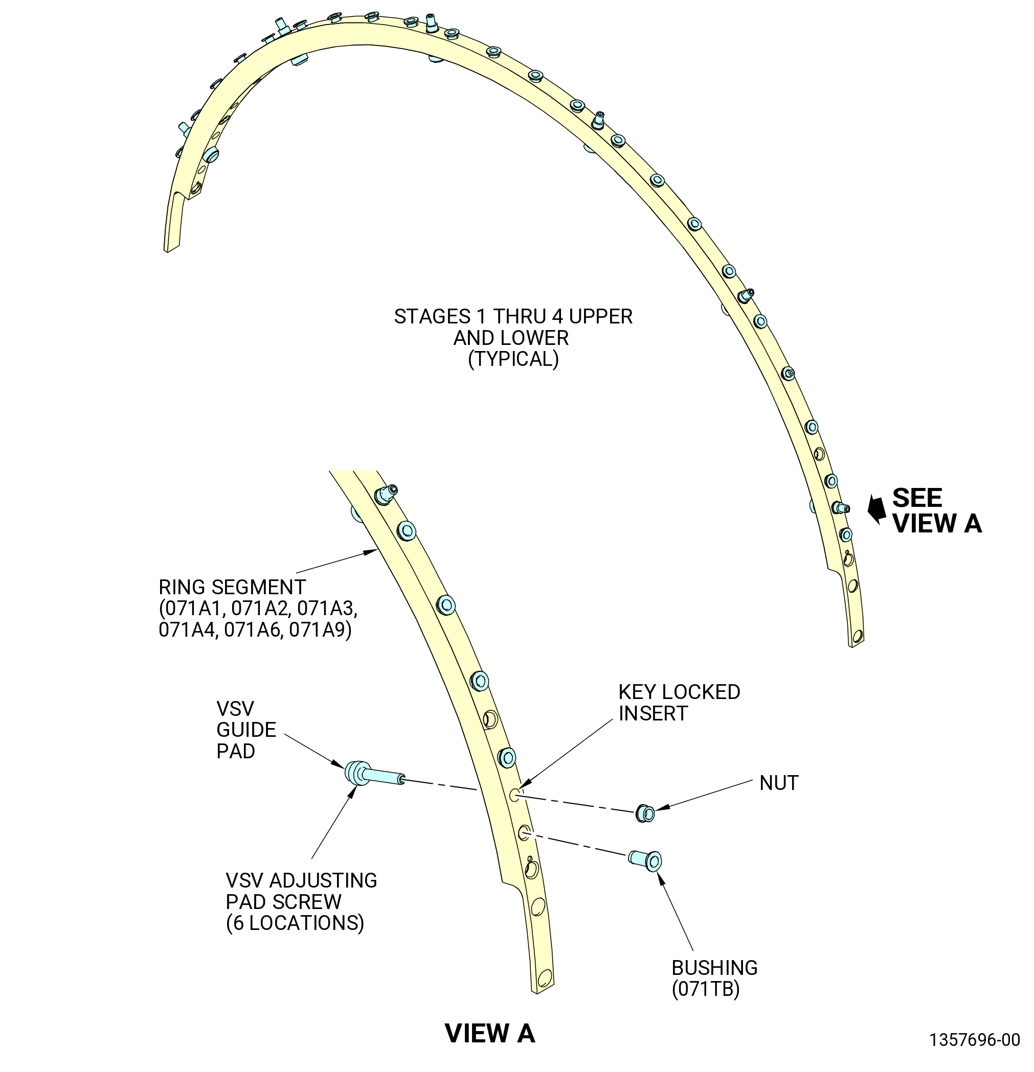
| F. | Disassemble the stage 1-4 ring segments (071A1, 071A2, 071A3, 071A4, 071A6, 071A9) as follows. Refer to Figure 509. |
| (1) | Deleted. |
| (2) | Remove the bushings (01-020) (SIN 071TB) from the ring segments as follows: |
| (a) | Attach the adapter puller (item 15) of the 11C3302 bushings pusher to the slide hammer (item 6). |
| (b) | Attach the grip (item 13) to the adapter puller (item 15). |
| (c) | Put the grip (item 13) in the bushing. |
| (d) | Use the slide hammer (item 6) to remove the bushings from the ring segment. |
| (e) | Discard the bushings. |