| GEnx-1B SERVICE BULLETIN - 72-0175 R02 | Revised: 11/29/2016 | |
| SB 72-0175 R02 ENGINE - Combustion Chamber Assembly (72-42-00) - Repair of Engines to Replace or Repair Combustor | Issued: 10/03/2013 | |
| GEnx-1B SERVICE BULLETIN - 72-0175 R02 | Revised: 11/29/2016 | |
| SB 72-0175 R02 ENGINE - Combustion Chamber Assembly (72-42-00) - Repair of Engines to Replace or Repair Combustor | Issued: 10/03/2013 | |
| GE PROPRIETARY INFORMATION | |
| The information contained in this document is GE proprietary information and is disclosed in confidence. It is the property of GE and shall not be used, disclosed to others or reproduced without the express written consent of GE, including, but without limitation, it is not to be used in the creation, manufacture, development, or derivation of any repairs, modifications, spare parts, designs, or configuration changes or to obtain FAA or any other government or regulatory approval to do so. If consent is given for reproduction in whole or in part, this notice and the notice set forth on each page of this document shall appear in any such reproduction in whole or in part. | |
| This technical data is considered EAR controlled pursuant to 15 CFR Parts 730-774 respectively. Transfer of this data by any means to a Non-US Person, whether in the United States or abroad, without the proper U.S. Government authorization (e.g., License, exemption, NLR, etc.), is strictly prohibited. | |
| Copyright (2016) General Electric Company, U.S.A. |
| TRANSMITTAL INFORMATION |
| REVISION 2 TO SERVICE BULLETIN 72-0175 |
| Revision 2 is issued to update paragraphs 1., PLANNING INFORMATION, 2., MATERIAL INFORMATION, and 3., ACCOMPLISHMENT INSTRUCTIONS. |
| Revision 1 was issued October 24, 2014. The original was issued October 03, 2013. Revision bars in the left margin identify changes. |
| 1. | PLANNING INFORMATION |
| A. | Effectivity |
| * * * FOR GEnx-1B64, -1B67, -1B70, -1B64/P1, -1B67/P1, -1B70/P1, -1B70C/P1, -1B70/72/P1, -1B70/75/P1, -1B74/75/P1, 1B75/P1, -1B64/P2, -1B67/P2, -1B70/P2, -1B70C/P2, -1B70/72/P2, -1B70/75/P2, 1B74/75/P2 |
| This Service Bulletin is applicable to all GEnx-1B engines. |
| B. | Description |
| This Service Bulletin provides a quick turn (Q/T) method to remove and reinstall the combustor. |
| C. | Compliance |
| Category 7 |
| GE recommends that you do this Service Bulletin at customer's convenience. |
| NOTE: |
|
| D. | Concurrent Requirements |
| Do GEnx-1B S/B 72-0106 when or before you do this Service Bulletin. |
| E. | Reason |
| (1) | Objective: |
| To enhance shop turn around time. |
| (2) | Condition: |
| Some engines are being removed prematurely from service for combustor removal. |
| (3) | Cause: |
| Removal and repair of the combustor. |
| (4) | Improvement: |
| The procedures defined within this Service Bulletin are optimized for repair of the combustor and verification of modular serviceability. |
| (5) | Substantiation: |
| Substantiation is by analysis. |
| F. | Approval |
| This Service Bulletin contains no modification information that revises the approved configuration and therefore does not require FAA approval. |
| G. | Manpower |
| After you get access to the engine, you will need approximately 2,000 man-hours to do the replacement portion of this Service Bulletin. |
| H. | Weight and Balance |
| Weight and balance are not changed. |
| I. | References (Use the latest version of these documents) |
| GEK 9250, Commercial Engine Standard Practices Manual (SPM) |
| GEnx-1B Boeing 787 Aircraft Maintenance Manual (AMM) |
| GEK 112851, GEnx-1B Engine Manual (EM) |
| GEK 112862, GEnx-1B Cleaning, Inspection, and Repair Manual (CIR) |
| GEK 112864, GEnx-1B Engine Illustrated Parts Catalog (EIPC) |
| GEnx-1B S/B 72-0106, ENGINE - Propulsor Module Assembly (72-00-00) - Introduction of New Seal P/N 2503M02P01 |
| GEnx-1B S/B 72-0113, ENGINE - Mid Fan Shaft (72-58-00) - Repair of Engines to Replace or Repair the Mid Fan Shaft |
| NOTE: |
|
| J. | Publications Affected |
| None. |
| K. | Interchangeability |
| Use in complete sets. |
| L. | Software Accomplishment Summary |
| Not applicable. |
| 2. | MATERIAL INFORMATION |
| A. | Material - Price and Availability |
| (1) | Parts necessary to do this Service Bulletin: |
|
| NP = Not Provisioned |
| NOTE: |
|
| NOTE: |
|
| NOTE: |
|
| (2) | Other Spare Parts: |
|
| NOTE: |
|
| NOTE: |
|
| NOTE: |
|
| NOTE: |
|
| NOTE: |
|
| NOTE: |
|
| (3) | Consumables: |
|
| B. | Industry Support Information |
| None. |
| C. | Configuration Chart |
|
| Operation Codes AD=Add RE=Replace RM=Remains. |
| Change Codes 2=Two-way interchangeable. 5=Qualified interchangeability. Refer to paragraph 1.K., Interchangeability. |
| Support Code A=Old parts will no longer be supplied. |
| D. | Parts Disposition |
| None. |
| E. | Tooling - Price and Availability |
|
|
| 3. | ACCOMPLISHMENT INSTRUCTIONS |
| A. | General |
| (1) | The engine disassembly procedure will start from either one of the actions that follow: |
| (a) | The fan case removed as a propulsor (M20 configuration). |
| (b) | The fan case and low pressure turbine (LPT) module removed (M60 configuration). |
| NOTE: |
|
| NOTE: |
|
| NOTE: |
|
| NOTE: |
|
| B. | Removal |
| (1) | Remove and disassemble the M10 engine as follows: |
| (a) | Remove the aft mount and thrust links. Refer to the GEnx-1B, Boeing 787 AMM, DMC-B787-A-G71-21-02-00A-520A-A. |
| (b) | Put the engine in the pedestals set or an overhead gantry system. Refer to the GEnx-1B EM, 72-00-00, SPECIAL PROCEDURE 003. |
| (c) | Remove the spinner, platforms, fan blades and fan module. Refer to the GEnx-1B EM, 72-00-01, REMOVAL 001. |
| (d) | Remove the LPT module from the engine. Refer to the GEnx-1B EM, 72-00-04, REMOVAL 001 and do as follows: |
| 1 | Calculate the LPT axial setting before removal of the LPT module as follows: |
| a | Rotate the LPT one time and measure dimension (LPT axial setting). Refer to the GEnx-1B EM, 72-00-04, INSTALLATION 001, Subtask 72-00-04-220-028, and do as follows: |
| (1) | If the axial position is within the required dimension
given in Subtask 72-00-04-220-037, continue to step 3.B.(1)(d)1 c . |
| (2) | If the axial position is not within the required dimension
given in Subtask 72-00-04-220-037, continue with step 3.B.(1)(d)1 b . |
| b | If the axial position is not within the required dimension, ensure the adjusting shim is changed accordingly to give a satisfactory dimension on assembly. Perfer to GEnx-1B EM, 72-00-04, Subtask 72-00-04-220-037. |
| c | Remove the brush seal support as an assembly. The brush seal can be used again subject to visual inspection. Refer to paragraph 3.C.(2)(c). |
| CAUTION: |
|
| 2 | Remove the AGB module. Refer to the GEnx-1B EM, 72-00-05, REMOVAL 001. |
| 3 | Remove the fuel nozzles No. 2, 12, and 19. Refer to the GEnx-1B EM, 72-41-00, DISASSEMBLY 001, CONFIG 01, Subtask 72-41-00-040-024 or DISASSEMBLY 001, CONFIG 02, Subtask 72-41-00-040-044. |
| 4 | Insert a 6 mm flexible borescope into the CDN where the fuel nozzle was removed and do an inspection of all the radial mixers for defects. |
| a | If there are no anti-rotation tabs missing from the radial mixers, continue with the removal of the remaining fuel nozzles and the disassembly of the engine. |
| b | If the radial mixers have missing anti-rotation tabs, do as follows: |
| (1) | Remove the remaining fuel nozzles from the lower quadrant and continue with the top of the engine. |
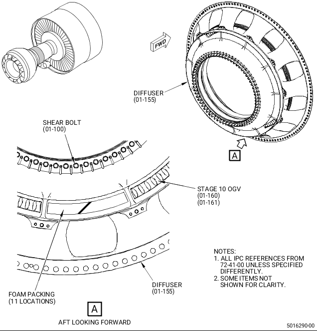
| (2) | As nozzles are removed, insert the foam packing into the CDN between the struts that block the gas path to the stage 10 OGV. Refer to Figure 1. |
| NOTE: |
|
| NOTE: |
|
| (3) | At fuel nozzles No. 9 thru No. 13 (lower quadrant), use a 6 mm flexible borescope to find all missing anti-rotation tabs. They could be in the dome assembly, between the dome assembly and stage 10 OGV airfoils, or on the CDN case between the combustor and CDN case. Try to recover all missing anti-rotation tabs. The anti-rotation tabs between the dome assembly and stage 10 OGV airfoils must be recovered. |
| (4) | Deleted. |
| 5 | Remove the LPT module. Refer to the GEnx-1B EM, 72-00-04, REMOVAL 001. |
| WARNING: |
|
| 6 | For pre-GEnx-1B S/B 72-0106 standard fan mid shaft (FMS), wipe the residual assembly C02-058 lubricant and loose dry graphite film with an oil wetted C10-182 cleaning cloth when the LPT retaining nut is removed and before the pusher tool is installed. |
| 7 | Do a final wipe with a C10-182 cleaning cloth moist with C04-003 acetone. Refer to the SPM, 70-21-23, CLEANING METHOD 23 - HAND-WIPE DEGREASING. |
| NOTE: |
|
| (2) | Remove the HPT module as follows: |
| (a) | Put the core module in the 9481M84 assembly stand or with the nose vertically down in the 11C4582 assembly stand. |
| (b) | Measure dimension ASACT, after removal of the No. 4 bearing retaining nut. Refer to the GEnx-1B EM, 72-00-02, ASSEMBLY 002, Subtask 72-00-02-500-003. |
| (c) | Remove the HPT rotor, stage 2 stator, and turbine center frame (TCF) as a whole assembly, but keep the combustor diffuser nozzle (CDN) assembly installed on the HPC. Refer to GEnx-1B EM, 72-00-02 DISASSEMBLY 001 thru DISASSEMBLY 006. |
| (d) | Record the position of CDP balance bolts to make sure that the new replacement balance bolts are installed in same location. |
| NOTE: |
|
| NOTE: |
|
| (e) | Use a C05-003 marking pen to put a correlation mark across the HPT stage 1 disk forward flange and CDP seal to make sure that the HPT is reinstalled in the same position that was previously installed. |
| (f) | Store the HPT rotor, stage 2 stator, and TCF on the 11C3010 build up fixture with the 11C3051 dummy CDN case. |
| NOTE: |
|
| (g) | Remove and discard the three bridge plates (34-330, 72-00-02), (34-340), and (34-350). |
| (3) | Remove the CDN as follows: |
| (a) | Disassemble the CDN module. Refer to the GEnx-1B EM, 72-40-00, DISASSEMBLY 001 and do as follows: |
| 1 | Remove the bolt covers and forward outer seal (FOS). Refer to the GEnx-1B EM, 72-40-00, DISASSEMBLY 001, Subtask 72-40-00-040-008. |
| NOTE: |
|
| 2 | Remove the nozzle support/stage 10 outlet guide vane (OGV) nuts. Refer to the GEnx-1B EM, 72-40-00, DISASSEMBLY 001, Subtask 72-40-00-040-013. |
| 3 | Remove the stage 1 nozzle support assembly and put the assembly in the 11C3081 stage 1 HPT nozzle assembly fixture. Refer to the GEnx-1B EM, 72-40-00, DISASSEMBLY 001, Subtask 72-40-00-040-006. |
| NOTE: |
|
| 4 | Reinstall two slave stage 10 OGV nuts to secure the stage 10 OGV. |
| 5 | If the fuel nozzles were not removed in paragraph 3.B.(3), remove them as follows: |
| a | Before the nozzle is removed, put a mark for the position number on it and record the fuel nozzle serial number by position. Refer to the GEnx-1B EM, 72-41-00, DISASSEMBLY 001, CONFIG 01, Subtask 72-41-00-040-024 or DISASSEMBLY 001, CONFIG 02, Subtask 72-41-00-040-044. |
| 6 | Remove the borescope plugs. Refer to the GEnx-1B EM, 72-41-00, DISASSEMBLY 001, Subtask 72-41-00-040-026. |
| 7 | Remove the combustion chamber from the CDN case with the 11C3050 combustor fixture. Refer to the GEnx-1B EM, 72-41-00, DISASSEMBLY 001, Subtask 72-41-00-040-008. |
| 8 | If foam packing was used to seal the area between the combustor and stage 10 OGV, remove all loose radial mixers and missing anti-rotation tabs. Make sure that all the radial mixers and anti-rotation tabs are accounted for (some can be located in the stage 1 nozzle inner and outer cooling air baffles). Remove the foam packing and make sure that there is no loose material that could fall into the HPC. |
| NOTE: |
|
| NOTE: |
|
| 9 | If there are missing anti-rotation tabs, do a visual inspection inside the forward inner nozzle support (FINS) cavity (borescope recommended) to find missing tabs. If more tabs are still missing, the stage 1 nozzle assembly must be disassembled to do an inspection of the inner baffle for evidence of missing tabs. Disassemble the stage 1 nozzle assembly as follows: |
| a | Put the nozzle assembly on the 11C3081 stage 1 HPT nozzle assembly fixture. |
| b | Remove the nozzles. Refer to the GEnx-1B EM, 72-51-00, DISASSEMBLY 001, Subtask 72-51-00-040-003. |
| C. | Inspection |
| NOTE: |
|
| (1) | Visually inspect the LPT/TRF module as follows: |
| (a) | Stage 1 LPT blade: |
| 1 | Looseness - any amount is permitted. |
| 2 | Blade corrosion - any amount is permitted. |
| (b) | Stage 7 LPT blade: |
| 1 | Looseness - any amount is permitted. |
| (c) | Stage 1 LPT shroud: |
| 1 | Stage 1 LPT shroud meets the inspection criteria. Refer to the GEnx-1B CIR, 72-00-04, INSPECTION 001, Subtask 72-00-04-220-034. |
| (d) | TRF: |
| 1 | FPI of the TRF case at the rear mount lug location is not required for Q/T engines as stated. Refer to the GEnx-1B CIR, 72-00-04, INSPECTION 001, Subtask 72-00-04-230-001. |
| (e) | FMS: |
| 1 | Missing paint/coating - touch up the paint. Refer to the SPM, 70-43-05, INORGANIC ALUMINUM PROTECTIVE COATING. |
| 2 | Galling on pilot diameters - any amount is permitted. |
| 3 | Corrosion on the No. 4 aft seal mounting flange - any amount is permitted. |
| 4 | Oil and coke deposits in the shaft internal diameter (ID) - any amount is permitted. |
| (2) | Do a visual inspection of the TCF module as follows: |
| (a) | Stage 1 LPT nozzle: |
| 1 | Corrosion - any amount is permitted. |
| 2 | Dents/impact damage - any amount is permitted if there is no missing material or cracking. |
| (b) | Stage 1 nozzle retainer: |
| 1 | Cracking - any amount is permitted. |
| 2 | Distortion - any amount less than 0.25 inch (6.4 mm) from the TCF aft flange is permitted. |
| (c) | Forward brush seal: |
| 1 | Damper panel rivets for looseness - any amount is permitted. |
| 2 | Damper panel missing rivets - none is permitted. |
| 3 | Damper panel cracks - none is permitted. |
| 4 | Brush seal bristles - general visual inspection (GVI), visibly worn bristles - none is permitted. |
| NOTE: |
|
| (d) | No. 4 bearing aft stationary air seal abradable seal surface: |
| 1 | A maximum wear of 0.022 inch (0.55 mm) in depth for a maximum of 3.00 inches (76.2 mm) in length on any seal groove. |
| 2 | The average rub groove wear must not exceed 0.010 inch (0.25 mm) in depth (average at eight equally spaced locations to include maximum wear rub location). |
| (3) | Do an inspection of the HPT stage 2 nozzle assembly as follows: |
| (a) | HPT stage 2 nozzle: |
| 1 | Airfoils and platforms - inspect as per borescope limits. Refer to the GEnx-1B, Boeing 787 AMM or GEnx-1B EM, 72-00-00, SPECIAL PROCEDURE 004. |
| 2 | Nozzle honeycomb rub depth - any amount is permitted. |
| (b) | HPT stage 1 and 2 shrouds: |
| 1 | Inspect as per borescope limits. Refer to the GEnx-1B, Boeing 787 AMM or GEnx-1B EM, 72-00-00 SPECIAL PROCEDURE 004. |
| (4) | Do and inspection of the HPT rotor assembly as follows: |
| (a) | Stage 1 and 2 blades: |
| 1 | Airfoil and platform defects - inspect as per borescope limits. Refer to the GEnx-1B, Boeing 787 AMM or GEnx-1B EM, 72-00-00 SPECIAL PROCEDURE 004. |
| (b) | Forward rotating seal coating: |
| 1 | Seal teeth missing coating - if the original CDN/FOS/honeycomb is used again, use the old forward rotating seal as it is. |
| 2 | If the original CDN/FOS/honeycomb is replaced with a new one or a different assembly is installed, reuse the original forward seal if it meets the criteria for missing coating. Refer to the GEnx-1B CIR, 72-00-53, INSPECTION 001, Subtask 72-00-53-220-007. |
| 3 | Seal tooth cracking is not permitted. |
| (5) | Do an inspection of the CDN assembly as follows: |
| (a) | Forward outer seal: |
| 1 | Honeycomb rub depth - any amount is permitted. |
| (b) | Stage 1 nozzle: |
| 1 | Airfoil and platform defects - inspect as per borescope limits. Refer to the GEnx-1B, Boeing 787 AMM or GEnx-1B EM, 72-00-00 SPECIAL PROCEDURE 004. |
| 2 | Remove or replace any broken or missing leaf seals and/or springs. Refer to the GEnx-1B EM, 72-51-20, REPAIR 001. |
| NOTE: |
|
| (c) | Cooling baffles of the stage 1 nozzles (OD): |
| 1 | Evidence of unwanted material in the cavity. Remove all blockages. If unable to remove, replace the nozzle. |
| (d) | Cooling baffles of the stage 1 nozzles (ID): |
| 1 | If necessary, do a borescope inspection for evidence of unwanted material in the cavity. Remove all blockages. If unable to remove, replace the nozzle. |
| (e) | Stage 10 OGV: |
| 1 | Honeycomb rub depth - any amount is permitted. |
| (f) | Fuel nozzles: |
| 1 | Inspection limits. Refer to the GEnx-1B, Boeing 787 AMM, DMC-B787-A-G72-00-00-07B-280C-A. For areas not identified in the AMM, apply GVI. |
| 2 | For GEnx-1B (PIP 2) config 2 engines removed for combustor swirler tab broken and swirlers rotation/disengagement, the fuel nozzles must be routed for flow check on a flow rig. |
| (g) | Forward inner nozzle support (FINS): |
| 1 | Do a visual inspection of the cavities of the FINS to make sure that no debris is present (for configuration PIP 2 only). |
| 2 | If the stage 1 nozzles were removed, do a visual inspection of the swaged nut threads for serviceability. Replace if required. Refer to the GEnx-1B CIR, 72-51-01, REPAIR 001. |
| 3 | Do a visual inspection of the FINS at the CDP bolt heat shield location for evidence of erosion. |
| a | If erosion is present, refer to the GEnx-1B EM, 72-51-01, subtask 72-51-01-220-061 for depth limits permitted. |
| (h) | Do a visual inspection of the cavities of the FINS to make sure that no debris is present (for configuration PIP 2 only). |
| 1 | If the stage 1 nozzles were removed, do a visual inspection of the swaged nut threads for serviceability. Replace if required. Refer to the GEnx-1B CIR, 72-51-01 REPAIR 001. |
| (i) | Combustor - replace the outer liner, this is a source controlled repair and must be accomplished at a GE approved facility. During replacement of the outer liner the remaining combustor must be inspected. Refer to the GEnx-1B, Boeing 787 AMM limits to do this inspection. For areas not identified in the AMM apply GVI. |
| (j) | Do an inspection of the combustor. Refer to the GEnx-1B EM, 72-00-00, SPECIAL PROCEDURE 004 and do as follows: |
| 1 | If the liners are unserviceable, replace them. This is a source controlled repair and must be done at a GE approved facility. Do an inspection of the remaining combustor liners during replacement of the outer liner. For areas not identified in the AMM, do a GVI. |
| 2 | Do an inspection to look for damage on the radial mixers, missing anti-rotation tabs, or radial mixers rotated out of engagement. No damage to the vanes or missing anti-rotation tabs are permitted. Replace the full set of radial mixers. Refer to paragraph 3.D., Repair to replace the radial mixers. |
| (k) | Do a visual inspection of the CDP manifold (in situ) using white light if required. - No cracks permitted. |
| (l) | Do a visual inspection of the limited visible portion of the diffuser tabs forward of the CDP Manifold inner retention location (in situ) using white light if required. - No cracks permitted. |
| (6) | Do a inspection of the HPT air guide tube as follows: |
| (a) | Do a GVI of the piston rings on site. Replace the piston rings if there are defects. If serviceable, use them again as they are without removal. |
| D. | Repair |
| (1) | If the combustor liners and dome assembly are serviceable as specified in paragraph 3.C., Inspection, but the radial mixers are unserviceable, replace the radial mixers and retainers to repair the combustor as follows: |
| WARNING: |
|
| (a) | Apply C02-053 penetrating oil to the bolts that will be removed. |
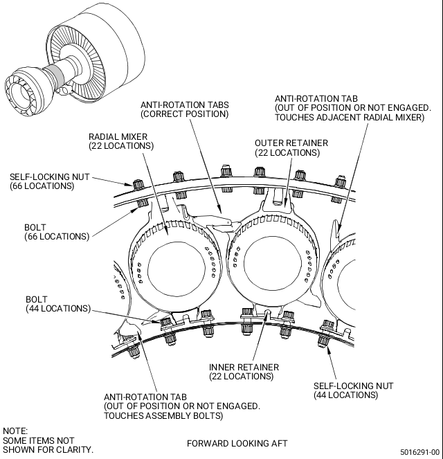
| (b) | Remove the 44 self-locking nuts (01-030, 72-42-00), bolts (01-020), and the 22 outer retainers (01-040). Do not remove the 22 self-locking nuts and bolts that are not attached to the outer retainers. Refer to Figure 2. |
| (c) | Remove and discard 11 radial mixers (01-080) or (01-081) and 11 radial mixers (01-070) or (01-071) from the dome assembly (01-090). These parts will not be used again. |
| (d) | Do a visual inspection of the dome assembly (01-090) forward side for damage as follows: |
| 1 | Do an inspection of the deflector braze for cracks: |
| Maximum serviceable limits : Any amount up to 1.00 inch (25.4 mm) in length is permitted as the maximum total length for each deflector. No spacing limit applies. |
| 2 | Do an inspection of the adjacent side of the dome plate eyelet for local damage: |
| Maximum serviceable limits : Cracks are not serviceable. Nicks, dents, or scratches are permitted up to 0.06 inch (1.5 mm) in size, any direction if the depth is not more than 0.005 inch (0.13 mm) after removal of high metal. If there are sharp edges, locally blend. Refer to the SPM, 70-42-00, BLENDING AND REMOVAL OF HIGH METAL PROCEDURES. |
| 3 | Do an inspection of the inner and outer dome assembly band for local damage: |
| Maximum serviceable limits : Cracks are not serviceable. Nicks, dents, or scratches are permitted up to 0.06 inch (1.5 mm) in size, any direction if the depth is not more than 0.005 inch (0.13 mm) after removal of high metal. If there are sharp edges, locally blend. Refer to the SPM, 70-42-00, BLENDING AND REMOVAL OF HIGH METAL PROCEDURES. |
| 4 | Do an inspection of the bolts (01-020) and inner retainers (01-060) for contact damage: |
| Maximum serviceable limits : Cracks or missing material are not serviceable. |
| (e) | Remove and discard the bolts (01-020) and inner retainers (01-060) as necessary. These parts will not be used again. |
| (f) | Replace the self-locking nuts (01-030), bolts (01-020), and inner retainers (01-060) with the new ones. Install them on one fuel nozzle at a time to prevent loosening on the inner flange. |
| WARNING: |
|
| 1 | Apply a small quantity of C02-058 lubricant on the washer faces and threads of each new bolt (01-020) that will be installed. |
| 2 | If only one damaged bolt (01-020) needs to be installed again, install a new bolt (01-020) from inside the dome assembly (01-090) and a self-locking nut (01-030). Torque the self-locking nut to 69-81 lb in. (7.8-9.2 N.m). |
| 3 | If the inner retainer (01-060) needs to be installed again, install new bolts (01-020) from inside the dome assembly (01-090) through a new inner retainer (01-060). Install the inner retainer (01-060) with the contact surface aft. Install a radial mixer in the fuel nozzle for reference. Attach the self-locking nuts (01-030) to the bolts (01-020) by hand. |
| 4 | Install a shim to make a clearance between each radial mixer and inner retainer. Make sure that the maximum clearance between the inner retainer and radial mixer is not more than 0.015 inch (0.38 mm). |
| 5 | Torque the two self-locking nuts (01-030) to 69-81 lb in. (7.8-9.2 N.m) to firmly attach the inner retainer (01-060). |
| 6 | Do an inspection again to make sure that the clearance is not more than 0.015 inch (0.38 mm) and the radial mixer is free to move. Loosen and reset the clearance and torque the self-looking nuts and bolts again to adjust the inner retainer if necessary. |
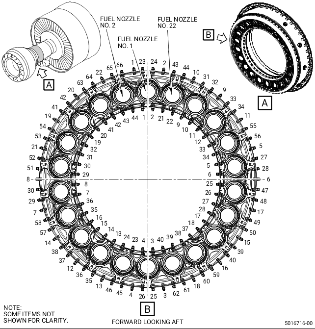
| (g) | Find the top of the combustor. Fuel nozzle No. 1 is in line with the top. The fuel nozzles numbers are located clockwise (CW), aft looking forward (ALF) (igniter ports are at the fuel nozzles No. 17 and No. 19 of 22). |
| 1 | Install 11 new radial mixers (01-080) or (01-081) in the odd number fuel nozzles. |
| 2 | Install 11 new radial mixers (01-070) or (01-071) in the even number fuel nozzles. |
| NOTE: |
|
| 3 | Make sure that all inner retainers are engaged correctly and that the anti-rotation tabs are in the correct position, adjacent to the anti-rotation tabs. Refer to Figure 2. |
| (h) | Install the new 22 outer retainers (01-040) with 44 new bolts (01-020) and self-looking nuts (01-030) as follows: |
| WARNING: |
|
| 1 | Apply a small quantity of C02-058 lubricant on the washer faces and threads of 44 new bolts (01-020) and self-looking nuts (01-030). |
| 2 | Install the new bolts (01-020) from inside the dome assembly through a new outer retainer (01-040). Install the outer retainer (01-040) with the contact surface aft. Attach the self-locking nut (01-030) to the bolt (01-0120) by hand. |
| 3 | Install a shim to make a clearance between each radial mixer and outer retainer. Make sure that the maximum clearance between the outer retainer and radial mixer is not more than 0.015 inch (0.38 mm). |
| 4 | Torque the self-looking nuts to 69-81 lb in. (7.8-9.1 N.m) in a criss-cross pattern. Refer to Figure 3 and do as follows: |
| a | Start to torque the self-locking nuts from bolthole No. 23 to No. 66. |
| NOTE: |
|
| b | Use the chart numbering to replace all the 44 outer bolts, and only the inner bolts when inner retainer replacement is necessary. |
| 6 | Do an inspection again to make sure that the clearance is not more than 0.015 inch (0.38 mm) and the radial mixer is free to move. Loosen and reset the clearance and torque the self-looking nuts and bolts again to adjust the outer retainer if necessary. |
| E. | Assembly |
| (1) | Assemble the combustor diffuser assembly. |
| (a) | Install the combustor as follows: |
| 1 | Install the combustion chamber assembly with the 11C3050 combustor fixture. Refer to the GEnx-1B EM, 72-41-00, ASSEMBLY 001, Subtask 72-41-00-440-024. |
| NOTE: |
|
| 2 | Make sure that the igniter plug immersion depth is in the dimensions required and correct if necessary. Refer to the GEnx-1B EM, 72-41-00, ASSEMBLY 001, CONFIG 01, Subtask 72-41-00-220-013 or ASSEMBLY 001, CONFIG 02, Subtask 72-41-00-220-020. |
| (2) | Assemble the CDN assembly. |
| (a) | Assemble the CDN as follows: |
| 1 | Install the stage 1 nozzle assembly. Refer to the GEnx-1B EM, 72-40-00, ASSEMBLY 001, Subtask 72-40-00-440-021. |
| NOTE: |
|
| 2 | Torque the stage 1 nozzle nuts and install the nut shields. Refer to the GEnx-1B EM, 72-40-00, ASSEMBLY 001, Subtask 72-40-00-440-040. |
| a | Do a visual inspection of the FINS at the CDP bolt shield location for evidence of erosion. |
| b | If erosion is present at the CDP bolt shield location, reinstall the CDP bolt shields so the split line is not at the same area of erosion, but rotate so mid span of the shield is at the area of erosion, insert shims between the heat shield and FINS to pre-load the shields radially inwards, install all other shields aligned with initial shield and also shim radialy inwards. Ensure all shims are removed when the nuts are torqued. Refer to the GEnx-1B, 72-40-00, ASSEMBLY 001, Subtask 72-40-00-440-167, CONFIGURATION 02. |
| 3 | Install the FOS support. Refer to the GEnx-1B EM, 72-40-00, ASSEMBLY 001, Subtask 72-40-00-440-023. |
| 4 | Install FOS retaining bolts and bolt shields. Refer to the GEnx-1B EM, 72-40-00, ASSEMBLY 001, Subtask 72-40-00-440-026 and Subtask 72-40-00-440-034. |
| 5 | Install the fuel nozzles. Refer to the GEnx-1B EM, 72-40-00, ASSEMBLY 001, Subtask 72-40-00-440-085. |
| 6 | Install the fuel manifolds and do a leak check. Refer to the GEnx-1B EM, 72-40-00, ASSEMBLY 001, Subtask 72-40-00-440-107 and Subtask 72-40-00-220-010. |
| NOTE: |
|
| 7 | Install the borescope plugs. Refer to the GEnx-1B EM, 72-40-00, ASSEMBLY 001, Subtask 72-40-00-440-119. |
| 8 | Install the CDN assembly on the HPC. |
| a | Torque the nut and bolts to install the CDN assembly to the HPC. Refer to the GEnx-1B EM, 72-00-02, ASSEMBLY 002, CONFIG 01 or 02. |
| b | Install brackets on the CDN assembly. Refer to the GEnx-1B EM, 72-00-02, ASSEMBLY 002, CONFIG 01 or 02. |
| (3) | Install the HPT module. |
| NOTE: |
|
| NOTE: |
|
| NOTE: |
|
| NOTE: |
|
| (a) | Install the CDP nuts and torque them with the 11C4525 torque wrench. Refer to the GEnx-1B EM, 72-00-02, ASSEMBLY 002, CONFIG 01 or 02. |
| (b) | Measure the HPT rotor runout check. Refer to the GEnx-1B EM, 72-00-02, ASSEMBLY 002, CONFIG 01, Subtask 72-00-02-430-725 or ASSEMBLY 002, CONFIG 02, Subtask 72-00-02-430-893. |
| (c) | Install HPT rotor air duct. Refer to the GEnx-1B EM, 72-00-02, ASSEMBLY 002, CONFIG 01 or 02. |
| (d) | Install the No. 4 bearing oil scoop and rotating seal (if previously removed) and measure dimension ASACT, this measurement must be in plus or minus 0.002 inch (0.05 mm) of dimension ASACT recorded during disassembly in paragraph 3.B (2) (b). Refer to the GEnx-1B EM, 72-00-02, ASSEMBLY 002, CONFIG 01 or 02. |
| (e) | Return the propulsor to the horizontal position either in the overhead gantry or pedestals. |
| (4) | Install the LPT as follows: |
| (a) | Install the LPT assembly. Refer to the GEnx-1B EM, 72-00-04, INSTALLATION 001 and do as follows: |
| 1 | Install the LPT module with the shim originally installed. |
| WARNING: |
|
| CAUTION: |
|
| 2 | Install the LPT nut as per the GEnx-1B, S/B 72-0113, with C02-019 engine oil or C02-023 engine oil. |
| 3 | Torque the LPT nut to 1,100-1,260 lb ft (1,491-1,708 N.m) and final torque another 20 degrees. |
| 4 | LPT axial setting (dimension R): |
| a | Measure dimension R. Alternative Procedure. Refer to the GEnx-1B EM, 72-00-04, INSTALLATION 001, Subtask 72-00-04-220-037. If the axial position is not within the required dimension, change the FMS shim to have dimension R within the required dimension. |
| b | Deleted. |
| c | Deleted. |
| 5 | Complete the LPT module installation and make sure that all the hardware previously removed in paragraph 3.B., Removal is installed back. |
| NOTE: |
|
| 6 | Install the aft mount and thrust links. Refer to the GEnx-1B, Boeing 787 AMM, DMC-B787-A-G71-21-02-00A-720A-A. |
| (5) | Install the AGB as follows: |
| (a) | Install the AGB module assembly. Refer to the GEnx-1B EM, 72-00-05, INSTALLATION 001. |
| (6) | Install the fan module assembly as follows: |
| (a) | Install the fan module assembly. Refer to the GEnx-1B EM, 72-00-01, INSTALLATION 001, CONFIG 01 OR 02. |
| F. | Test |
| (1) | Do a test either in a test cell or on wing as follows: |
| (a) | If the test is done in a test cell, do an acceptance test. Refer to the GEnx-1B EM, 72-00-00, TESTING 001 thru TESTING 005. |
| (b) | If the test is done on wing, refer to the GEnx-1B, Boeing 787 AMM, 71-00-00, TESTING 008 for untested engines. |