| GEnx-1B SERVICE BULLETIN - 72-0524 R00 | Revised: 08/16/2023 | |
| SB 72-0524 R00 ENGINE - Combustor Diffuser Assembly (72-41-00) - In-Shop Introduction of New Combustor Case Free-Running Insert and Locking Ring | Issued: 08/16/2023 | |
| GEnx-1B SERVICE BULLETIN - 72-0524 R00 | Revised: 08/16/2023 | |
| SB 72-0524 R00 ENGINE - Combustor Diffuser Assembly (72-41-00) - In-Shop Introduction of New Combustor Case Free-Running Insert and Locking Ring | Issued: 08/16/2023 | |
| GE Designated: -CONFIDENTIAL- | |
| The information contained in this document is GE proprietary information and is disclosed in confidence. It is the property of GE and shall not be used, disclosed to others or reproduced without the express written consent of GE, including, but without limitation, it is not to be used in the creation, manufacture, development, or derivation of any repairs, modifications, spare parts, designs, or configuration changes or to obtain FAA or any other government or regulatory approval to do so. If consent is given for reproduction in whole or in part, this notice and the notice set forth on each page of this document shall appear in any such reproduction in whole or part. | |
| This technical data is considered subject to the Export Administration Regulations (EAR) pursuant to 15 CFR Parts 730-774. Transfer of this data by any means to a Non-U.S. Person, whether in the United States or abroad, without the proper U.S. Government authorization (e.g., License, exemption, NLR, etc.), is strictly prohibited. | |
| Copyright (2023) General Electric Company, U.S.A. |
| 1. | PLANNING INFORMATION |
| A. | Effectivity |
| * * * FOR GEnx-1B64, -1B64/P1, -1B64/P2, -1B67, -1B67/P1, -1B67/P2, -1B70, -1B70/75/P1, -1B70/75/P2, -1B70/P1, -1B70/P2, -1B70C/P1, -1B70C/P2, -1B74/75/P1, -1B74/75/P2, -1B76/P2, -1B76A/P2 |
| This Service Bulletin is applicable to these GEnx-1B engines: |
| • |
|
| These serial numbers are the best available data. |
| The combustor cases P/N 2303M23G11, P/N 2303M23G19 , P/N 2303M23G20, P/N 2303M23G21, P/N 2405M02G01, P/N 2417M02G01, and P/N 2417M03G01 with locking ring P/N 1689M74P08 and screw insert P/N 1693M83P15 are affected by this Service Bulletin. |
| B. | Description |
| This Service Bulletin allows field rework of the affected combustor cases by the replacement of the old locking ring and old screw insert with the new free-running thin wall insert and locking ring (free-running insert and locking ring) P/N J1484P08. |
| C. | Compliance |
| Category 3 |
| GE recommends that you do this Service Bulletin at the next shop visit of the engine/module. |
| Impact C |
| This recommendation is to address a condition that may result in a Non-Event operational disruption, Unscheduled Engine Removals (UER), Out-Station-Removals or Aircraft on the Ground (AOG). |
| NOTE: |
|
| This Service Bulletin is offered to improve the reliability or performance of your GE product, or to help prevent the occurrence of the event or condition described in this Service Bulletin. If the operator elects not to participate in the bulletin, that decision will be taken into consideration by GE in evaluating future product performance issues that may arise in the operator’s fleet. |
| D. | Concurrent Requirements |
| Do GEnx-1B S/B 73-0103 when you do this Service Bulletin. |
| E. | Reason |
| (1) | Objective: |
| To introduce a new part, rework parts, improve reliability, and improve maintainability. |
| (2) | Condition: |
| The current locking ring and screw insert may cause the machine bolt to get seized. The seized machine bolt can be damaged during removal. |
| (3) | Cause: |
| The current locking ring and screw insert failures are caused by a high initial running torque on the assembly and seizure on the disassembly. |
| (4) | Improvement: |
| The new type design free-running insert and locking ring has no self-locking feature. The new type design improves overall the fuel nozzle and igniter plug adapter bolted joint capability. The new free-running insert and locking ring lower the potential of getting the machine bolt seized, damaged, or broken. |
| (5) | Substantiation: |
| Substantiation is by analysis, comparative analysis, test, and fleet experience. |
| F. | Approval |
| The data contained in this Service Bulletin has been reviewed by the FAA or authorized entity representing the FAA and the repair(s) and modification(s) herein comply with the applicable Aviation Regulations and are APPROVED for installation in the model(s) listed in this Service Bulletin. |
| G. | Manpower |
| No additional man-hours are required to comply with this Service Bulletin. |
| H. | Weight and Balance |
| Weight and balance are not changed. |
| I. | References (Use the latest version of these documents) |
| GEK 112851, GEnx-1B Engine Manual (EM) |
| GEK 112862, GEnx-1B Cleaning, Inspection, and Repair Manual (CIR) |
| GEK 112864, GEnx-1B Engine Illustrated Parts Catalog (EIPC) |
| GEnx-1B S/B 73-0103, ENGINE FUEL AND CONTROL - Fuel Injection Nozzles (73-11-30) - In-Shop Fuel Nozzle Machine Bolt Replacement with Safety Cable Installation |
| NOTE: |
|
| J. | Publications Affected |
| GEK 112851, GEnx-1B Engine Manual (EM) |
| GEK 112862, GEnx-1B Cleaning, Inspection, and Repair Manual (CIR) |
| GEK 112864, GEnx-1B Engine Illustrated Parts Catalog (EIPC) |
| K. | Interchangeability |
| Qualified interchangeability. |
| The combustor cases P/N 2303M23G11, P/N 2303M23G19 , P/N 2303M23G20, P/N 2303M23G21, P/N 2405M02G01, P/N 2417M02G01, and P/N 2417M03G01 with the old locking ring P/N 1689M74P08 and the old screw insert P/N 1693M83P15 can be reworked to the combustor case with the new free-running insert and locking ring P/N J1484P08. |
| As part of field rework, the entire set of the old locking ring P/N 1689M74P08 and the old screw insert P/N 1693M83P15 are replaced with the new free-running insert and locking ring P/N J1484P08. As part of field rework combustor case part number remains unchanged. The new free-running insert and locking ring P/N J1484P08 require installation of machine bolts with safety cable/wire released per GEnx-1B S/B 73-0103. Refer to paragraph 1.D., Concurrent Requirements. |
| L. | Software Accomplishment Summary |
| Not applicable. |
| 2. | MATERIAL INFORMATION |
| A. | Material - Price and Availability |
| (1) | Parts necessary to do this Service Bulletin: |
|
| NOTE: |
|
| (2) | Other Spare Parts: |
| None. |
| (3) | Consumables: |
| None. |
| B. | Industry Support Information |
| None. |
| C. | Configuration Chart |
|
||||||||||||||||||||||||||||||||||||||||||||||||||||||||||||||||||||||||||||||||||||||||||||||||||||||||||||||||||||||||||||||||||||||||||||||||||||||||||||||||||||||||||||||||||||||||||||||||||||||||||||||||||||||||||||||||||||||||||||||||||||||||||||||||||||||||||||||||||||||||||||||||||||||||||||||||||||||||||||||||||||||||||||||||||||||||||||||||||||||||||||||||||||||||||||||||||||||||||||||||||||||||||||||||||||||||||||||||||||||||||||||||||||||||||||||||||||||||||||||||||||||||||||||||||||||||||||||||||||||||||||||||||||||||||||||||||||||||||||||||||||||||||||||||||||||||||||||||||||||||||||||||||||||||||||||||||||||||||||||||||||||||||||||||||||||||||||||||||||||||||||||||||
| Operation Codes AD=Add DE=Delete RM=Remains |
| Change Codes 5=Qualified interchangeability. Refer to paragraph 1.K., Interchangeability. |
| Support Codes B=Old parts will be supplied until all old parts are sold. |
| D. | Parts Disposition |
| Discard old parts. |
| E. | Tooling - Price and Availability |
|
| 3. | ACCOMPLISHMENT INSTRUCTIONS |
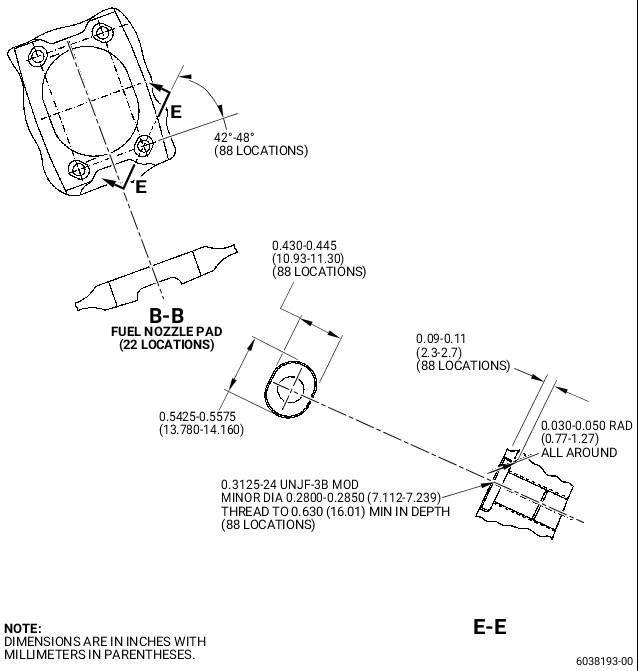
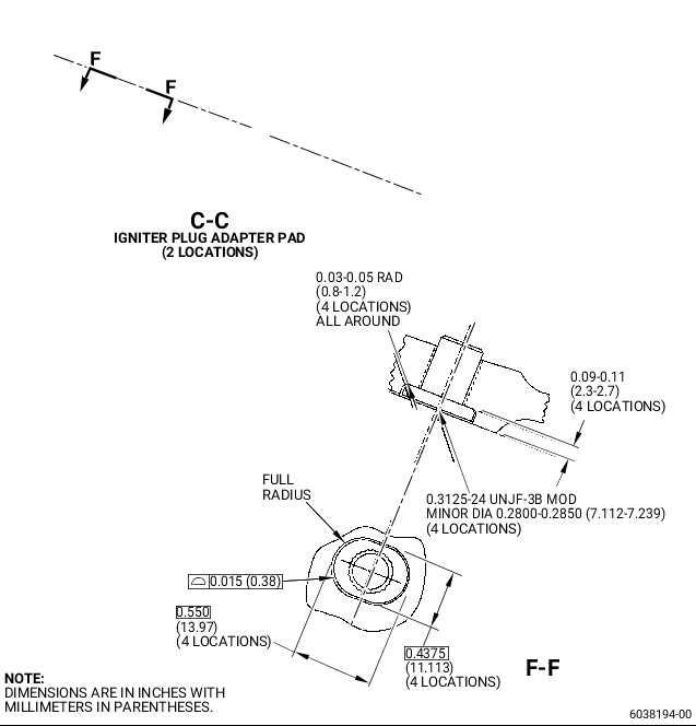
| A. | Fuel Nozzle Pad and Igniter Plug Adapter Pad Screw Insert Replacement |
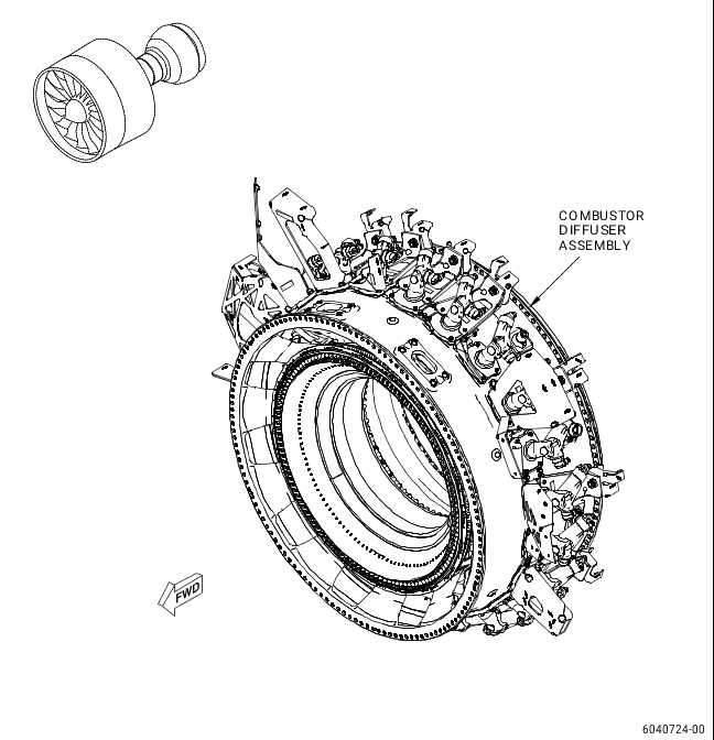
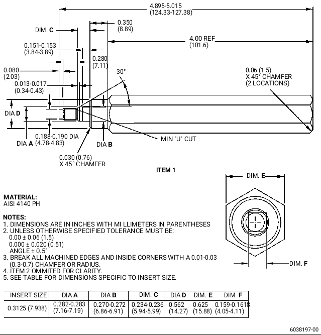
| (1) | Remove the fuel nozzles and igniter plug adapters from the combustor diffuser assembly (Figure 1) as necessary. Removal instructions have not changed. Refer to the GEnx-1B EM, 72-41-00, DISASSEMBLY 001, CONFIG 01 or CONFIG 02. |
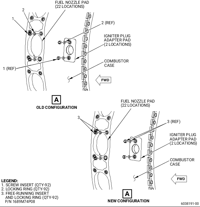
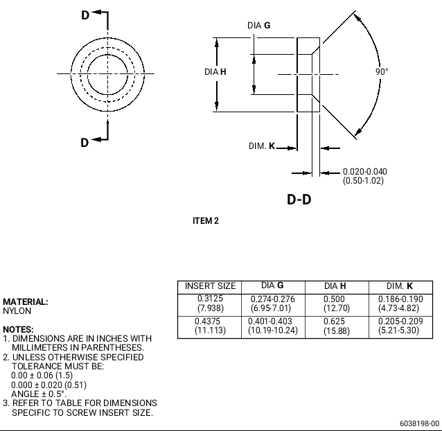
| (2) | Remove the entire set of the old screw insert (1, Figure 2) and locking ring (2) from the combustor case. Removal instructions have not changed. Refer to the GEnx-1B CIR, 72-41-01, REPAIR 001. |
| (3) | Do a no-go pin gage check of the combustor case threaded hole minor diameter. Refer to the GEnx-1B CIR, 72-41-01, REPAIR 001. |
| NOTE: |
|
| (4) | Install the new free-running insert and locking ring (3, Figure 2) in the threaded hole. Refer to Figure 3, Figure 4, Figure 5, and do as follows: |
| (a) | Make sure that you remove all the unwanted material from the threaded hole and the counter bore before you install the new free-running insert and locking ring (3, Figure 2). |
| (b) | For the screw inserts in the fuel nozzle pads, install the new free-running insert and locking rings (3) as follows: |
| 1 | Put the screw insert of the new free-running insert and locking ring (3) into the threaded hole. |
| 2 | Turn the screw insert of the new free-running insert and locking ring (3). Refer to Figure 5 and do as follows: |
| NOTE: |
|
| a | Alternative Procedure Available. Use a drive tool SR25W4A. |
| b | Alternative Procedure. Use a locally manufactured square wrench [0,173 inch x 0,173 inch (4.40 mm x 4.40 mm)]. |
| c | Install the screw insert of the new free-running insert and locking ring (3, Figure 2) in the combustor case until the top face of the screw insert is 0.01 to 0.03 inch (0.3 to 0.7 mm) below the combustor case surface. |
| 3 | Put the locking ring of the new free-running insert and locking ring (3) on the screw insert of the new free-running insert and locking ring (3) and into the oval shaped hole of the combustor case as follows: |
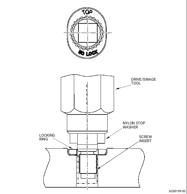
| a | Make sure that the words TOP and NO LOCK on the locking ring of the new free-running insert and locking ring (3) show at the outer side of the combustor case. Refer to Figure 4. |
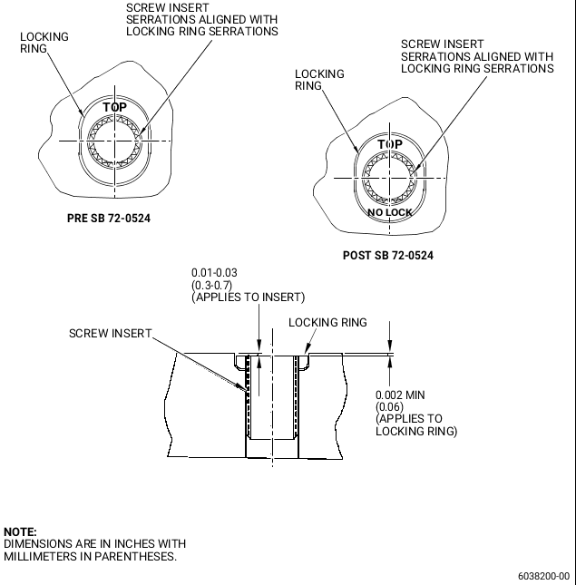
| b | Align the serrations on the screw insert of the new free-running insert and locking ring (3, Figure 2) with the serrations of the locking ring of the new free-running insert and locking ring (3). Refer to Figure 5. |
| (c) | For the screw inserts in the igniter plug adapter pads, install the new free-running insert and locking rings (3, Figure 2) as follows: |
| 1 | Put the screw insert of the new free-running insert and locking ring (3) into the threaded hole. |
| 2 | Turn the screw insert of the new free-running insert and locking ring (3). Refer to Figure 5 and do as follows: |
| NOTE: |
|
| a | Alternative Procedure Available. Use a drive tool SR25W4A. |
| b | Alternative Procedure. Use a locally manufactured square wrench [0,173 inch x 0,173 inch (4.40 mm x 4.40 mm)]. |
| c | Install the screw insert of the new free-running insert and locking ring (3, Figure 2) in the combustor case until the top face of the screw insert is 0.01 to 0.03 inch (0.3 to 0.7 mm) below the combustor case surface. |
| 3 | Put the locking ring of the new free-running insert and locking ring (3) on the screw insert of the new free-running insert and locking ring (3) and into the oval shaped hole of the combustor case as follows: |
| a | Make sure that the words TOP and NO LOCK on the locking ring of the new free-running insert and locking ring (3) show at the outer side of the combustor case. Refer to Figure 5. |
| b | Align the serrations on the screw insert of the new free-running insert and locking ring (3, Figure 2) with the serrations of the locking ring of the new free-running insert and locking ring (3). Refer to Figure 5. |
| (d) | For all the new free-running insert and locking rings (3, Figure 2), swage the screw insert of the new free-running insert and locking rings (3) as follows: |
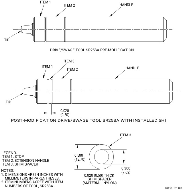
| 1 | Alternative procedure available. Use the drive/swage tool SR25SA (Figure 4) with the modification as follows: |
| NOTE: |
|
| a | Install a 0.020 inch (0.50 mm) thick shim spacer (item 3) between the stop (item 1) and the extension handle (item 2). Refer to Figure 4. |
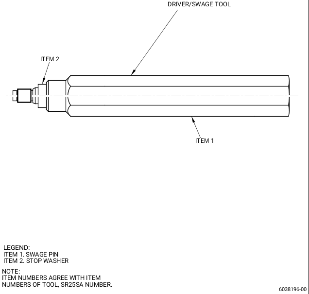
| 2 | Alternative procedure. Make the drive/swage tool. Refer to Figure 4. |
| 3 | Put the drive/swage tool into the new free-running insert and locking ring (3, Figure 2). |
| 4 | Push the locking ring of the new free-running insert and locking ring (3) to make sure that it makes contact with the bottom of the counter bore. |
| 5 | Use a hammer to tap the drive/swage tool until the nylon stop washer of the drive/swage tool touches the pad on the combustor case. |
| 6 | Remove the drive/swage tool. |
| (5) | Do an inspection of the new free-running insert and locking rings (3, Figure 2) as follows: |
| (a) | Use 10X magnification. |
| (b) | Make sure that the screw insert serrations of the new free-running insert and locking ring (3) are aligned with the locking ring serrations of the new free-running insert and locking ring (3). Refer to Figure 5. |
| (c) | Make sure that the screw insert of the new free-running insert and locking ring (3, Figure 2) is 0.01 to 0.03 inch (0.3 to 0.7 mm) below the combustor case surface. Refer to Figure 5. |
| (d) | Make sure that the locking ring of the new free-running insert and locking ring (3, Figure 2) is a minimum of 0.002 inch (0.06 mm) below the combustor case surface. Refer to Figure 5. |
| WARNING: |
|
| (e) | Use a pointed pick to try to lift the locking ring of the new free-running insert and locking ring (3, Figure 2) with light hand pressure on the pick and do as follows: |
| 1 | Make sure that the locking ring of the new free-running insert and locking ring (3) does not lift out of the counter bore. |
| (6) | Install the removed fuel nozzles and igniter plug adapters on the combustor diffuser assembly (Figure 1). Installation instructions have not changed. Refer to the GEnx-1B EM, 72-41-00, ASSEMBLY 001, CONFIG 01 or CONFIG 02. |