| GEnx-1B SERVICE BULLETIN - 73-0011 R03 | Revised: 06/16/2015 | |
| SB 73-0011 R03 ENGINE FUEL AND CONTROL - Flow Splitting Valve (73-21-30) - Fuel Accumulator Hardware Release | Issued: 11/30/2012 | |
| GEnx-1B SERVICE BULLETIN - 73-0011 R03 | Revised: 06/16/2015 | |
| SB 73-0011 R03 ENGINE FUEL AND CONTROL - Flow Splitting Valve (73-21-30) - Fuel Accumulator Hardware Release | Issued: 11/30/2012 | |
| GE PROPRIETARY INFORMATION | |
| The information contained in this document is GE proprietary information and is disclosed in confidence. It is the property of GE and shall not be used, disclosed to others or reproduced without the express written consent of GE, including, but without limitation, it is not to be used in the creation, manufacture, development, or derivation of any repairs, modifications, spare parts, designs, or configuration changes or to obtain FAA or any other government or regulatory approval to do so. If consent is given for reproduction in whole or in part, this notice and the notice set forth on each page of this document shall appear in any such reproduction in whole or in part. | |
| This technical data is considered EAR controlled pursuant to 15 CFR Parts 730-774 respectively. Transfer of this data by any means to a Non-US Person, whether in the United States or abroad, without the proper U.S. Government authorization (e.g., License, exemption, NLR, etc.), is strictly prohibited. | |
| Copyright (2015) General Electric Company, U.S.A. |
| TRANSMITTAL INFORMATION |
| REVISION 3 TO SERVICE BULLETIN 73-0011 |
| Revision 3 is issued to update paragraphs 1.B., Description , 2.A., Material - Price and Availability , and 3., ACCOMPLISHMENT INSTRUCTIONS . |
| Revision 2 was issued October 30, 2013. Revision 1 was issued May 16, 2013. The original was issued November 30, 2012. Revision bars in the left margin identify changes. |
| 1. | PLANNING INFORMATION |
| A. | Effectivity |
| * * * FOR GEnx-1B64, -1B64/P1, -1B67, -1B67/P1, -1B70, -1B70/P1, -1B70/75/P1 |
| This Service Bulletin is applicable to all GEnx-1B engines. |
| This Service Bulletin has been introduced in production to these GEnx-1B engines: |
| • |
|
| These serial numbers are the best available data. |
| The flow splitting valve (FSV) VIN 8104-018 (P/N 2140M55P01) is affected by this Service Bulletin. |
| B. | Description |
| This Service Bulletin provides disassembly and assembly instructions for the current and new fuel accumulator system on the GEnx-1B engines. |
| C. | Compliance |
| Category 2 |
| GE recommends that you do this Service Bulletin as soon as possible without effect on revenue service but before December 31, 2014. |
| NOTE: |
|
| This Service Bulletin is offered to improve the reliability or performance of your GE product, or to help prevent the occurrence of the event or condition described in this Service Bulletin. If the operator elects not to participate in the bulletin, that decision will be taken into consideration by GE in evaluating future product performance issues that may arise in the operators fleet. |
| D. | Concurrent Requirements |
| It is recommended that GEnx SB 73-0018 be incorporated along with or prior to accomplishment of this Service Bulletin. |
| E. | Reason |
| (1) | Objective: |
| To introduce new parts and reduce fuel vapor after engine shutdown. |
| (2) | Condition: |
| The occasional emission of fuel vapor from the engine at shutdown has resulted in the creation of a new FSV with fuel accumulator. The fuel accumulator has been defined to capture the fuel expelled from the fuel manifolds before it is released in the combustion chamber. Additional hardware is changing to support routing and interface changes. |
| (3) | Cause: |
| At engine shutdown, fuel in the manifold is pressurized sufficient to leak fuel into the combustor through the fuel nozzles. When contacting hot surfaces the fuel vaporizes and is emitted from the engine. There is no current system on the GEnx-1B engines that can eliminate the fuel vapor leakage after shutdown. |
| (4) | Improvement: |
| The fuel accumulator system is herein released to eliminate fuel vapor leakage after shutdown of the engine. After the addition of the fuel accumulator hardware, the GEnx-1B engines will comply with regulations regarding fuel vapor leakage after shutdown. This document provides the assembly and disassembly instructions to retrofit field engines via a Category 2 Service Bulletin. |
| (5) | Substantiation: |
| Substantiation is by comparative analysis and test. |
| F. | Approval |
| This Service Bulletin has been reviewed by the FAA and the repair(s) and modification(s) herein comply with the applicable Federal Aviation Regulations and are FAA APPROVED for installation in the model(s) listed in this Service Bulletin. |
| G. | Manpower |
| After you open the cowlings for an on wing or an in shop accomplishment of the flow splitting valve replacement on the engine to add the accumulator, you will need approximately 45 man-hours (three-men crew: Two men, full time for 18 hours, and one man, half-time) per engine to upgrade to this Service Bulletin. |
| H. | Weight and Balance |
| The complete compliance with this Service Bulletin increases engine weight by 11.4 lb (5.17 kg). |
| I. | References (Use the latest version of this document) |
| GEK 9250, Commercial Engine Standard Practices Manual (SPM) |
| GEK 112851, GEnx-1B Engine Manual (EM) |
| GEK 112862, GEnx-1B Cleaning, Inspection, and Repair Manual (CIR) |
| GEK 112864, GEnx-1B Engine Illustrated Parts Catalog (EIPC) |
| GEnx-1B S/B 73-0018, ENGINE FUEL AND CONTROL - Electronic Engine Control (73-21-20) - Release of EEC software version B140 |
| GEnx-1B Boeing 787 Aircraft Maintenance Manual (AMM) |
| NOTE: |
|
| J. | Publications Affected |
| GEK 112851, GEnx-1B Engine Manual (EM) |
| GEK 112862, GEnx-1B Cleaning, Inspection, and Repair Manual (CIR) |
| GEK 112864, GEnx-1B Engine Illustrated Parts Catalog (EIPC) |
| GEnx-1B Boeing 787 Aircraft Maintenance Manual (AMM) |
| K. | Interchangeability |
| The introduction of the kit hardware for the accumulator retrofit needs to be done as a set to meet functional requirements per kit P/N RPK619G01. Mixing of the proposed and superseded hardware is not permitted. |
| L. | Software Accomplishment Summary |
| Not applicable. |
| 2. | MATERIAL INFORMATION |
| A. | Material - Price and Availability |
| (1) | Parts necessary to do this Service Bulletin: |
|
|||||||||||||||||||||||||||||||||||||||||||||||||||||||||||||||||||||||||||||||||||||||||||||||||||||||||||||||||||||||||||||||||||||||||||||||||||||||||||||||||||||||||||||||||||||||||||||||||||||||||||||||||||||||||||||||||||||||||||||||||||||||||||||||||||||||||||||||||||||||||||||||||||||||||||||||||||||||||||||||||||||||||||||||||||||||||||||||||||||||||||||||||||||||||||||||||||||||||||||||||||||||||||||||||||||||||||||||||||||||||||||||||||||||||||||||||||||||||||||||||||||||||||||||||||||||||||||||||||||||||||||||||||||||||||||||||||||||||||||||||||||||||||||||||||||||||||||||||||||||||||||||||||||||||||||||||||||||||||||||||||||||||||||||||||||||||||||||||||||||||||||||||||||||||||||||||||||||||||||||||||||||||||||||||||||||||||||||||||||||||||||||||||||||||||||||||||||||||||||||||||||||||||||||||||||||||||||||||||||||||||||||||||||||||||||||||||||||||||||||||||||||||||||||||||||||||||||
| NOTE: |
|
| *****Part not supplied by GE Engine Services Distribution L.L.C. Procure through the following: |
| Woodward Governor Co. 5001 North Second Street P.O. Box 7001 Rockford, Illinois 61125-7001 U.S.A. |
| ******Part not supplied by GE Engine Services Distribution L.L.C. Procure through the following: |
| Elano Corp. 2455 Dayton-Xenia Rd. Dayton, OH 45434-7199 U.S.A. |
| (2) | Other Spare Parts: None. |
| (3) | Consumables: |
|
| B. | Industry Support Information |
| Contact your Customer Support Manager (CSM) for industry support information. |
| C. | Configuration Chart |
|
|||||||||||||||||||||||||||||||||||||||||||||||||||||||||||||||||||||||||||||||||||||||||||||||||||||||||||||||||||||||||||||||||||||||||||||||||||||||||||||||||||||||||||||||||||||||||||||||||||||||||||||||||||||||||||||||||||||||||||||||||||||||||||||||||||||||||||||||||||||||||||||||||||||||||||||||||||||||||||||||||||||||||||||||||||||||||||||||||||||||||||||||||||||||||||||||||||||||||||||||||||||||||||||||||||||||||||||||||||||||||||||||||||||||||||||||||||||||||||||||||||||||||||||||||||||||||||||||||||||||||||||||||||||||||||||||||||||||||||||||||||||||||||||||||||||||||||||||||||||||||||||||||||||||||||||||||||||||||||||||||||||||||||||||||||||||||||||||||||||||||||||||||||||||||||||||||||||||||||||||||||||||||||||||||||||||||||||||||||||||||||||||||||||||||||||||||||||||||||||||||||||||||||||||||||||||||||||||||||||||||||||||||||||||||||||||||||||||||||||||||||||||||||||||||||||||||||||||||||||||||||||||||||||||||||||||||||||||||||||||||||||||||||||||||||||||||||||||||||||||
| Operation Codes AD=Add DE=Delete RE=Replace RM=Remains RW=Rework QTC=Quantity Change |
| Change Code 5=Qualified interchangeability. Refer to paragraph 1.K., Interchangeability. |
| Support Codes A=Old parts will no longer be supplied. C=Old parts will be supplied until January, 2015. E=Old parts will be supplied, and can be used at other engine locations. |
| D. | Parts Disposition |
| Retain the temperature sensor (01-010, 73-31-05) (SIN 65T01) to use it as a spare part. The same sensor is used in two other locations on same engine model. |
| Use serviceable old parts for engines that have not changed. |
| E. | Tooling - Price and Availability |
|
| 3. | ACCOMPLISHMENT INSTRUCTIONS |
| A. | General |
| (1) | For on wing engine installations, do as follows: |
| (a) | Before this Service Bulletin is done, read the assembly and disassembly techniques section. Refer to the GEnx-1B Boeing 787 AMM, Standard Practices, G70-00-01, ASSEMBLY AND DISASSEMBLY TECHNIQUES MAINTENANCE PRACTICES. |
| (b) | Do a general visual inspection of the engine parts that are exposed during maintenance and all the parts that will be installed again. Refer to the GEnx-1B, CIR, INSPECTION 001, Subtask 72-00-00-220-055. |
| (c) | Prepare the engine and aircraft for maintenance. Refer to the Boeing 787 AMM, DMC-B787-A-G73-11-11-00A-520A-A, steps 1.B. |
| CAUTION: |
|
| NOTE: |
|
| NOTE: |
|
| NOTE: |
|
| (2) | For in shop engine installations, do as follows: |
| (a) | Before this Service Bulletin is done, read the assembly and disassembly techniques section. Refer to the SPM, 70-10-00, ASSEMBLY AND DISASSEMBLY TECHNIQUES. |
| (b) | Do a general visual inspection of the engine parts that are exposed during maintenance and all parts that will be installed again. |
| (c) | This procedure does not give instructions for removal or installation of engine build-up hardware. Refer to the GEnx-1B Boeing 787 AMM, as required. |
| B. | Disassembly of the FSV and External Hardware |
| NOTE: |
|
| (1) | Drain the engine fuel system as follows: |
| (a) | Drain the fuel. Remove the main fuel filter drain plug and main fuel pump strainer drain plug. Refer to the GEnx-1B Boeing 787 AMM, DMC-B787-A-G73-11-11-00A-520A-A, step 1.C.1 for the main fuel filter, and step 1.C.2, reference drain plug (7) only. |
| (b) | After completion, replace the main fuel filter drain plug preformed packing (P/N 1391-0052) and main fuel pump strainer drain plug preformed packing (P/N 1355-1349). Refer to the GEnx-1B Boeing 787 AMM, DMC-B787-A-G73-11-11-00A-720A-A. |
| (c) | Safety the drain plugs with C10-143 safety cable or C10-071 safety wire. |
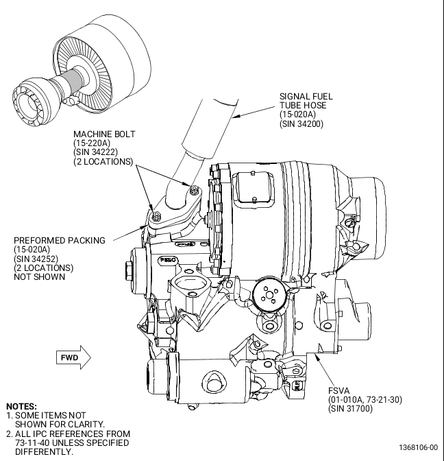
| (d) | To drain the fuel from the FSV (01-010, 73-21-30) (SIN 31700) and flowmeter outlet fuel tube (05-010, 73-11-41) (SIN 34401), put a 5 gallon (18.9 liters) fuel resistant container STD-201 below the fuel flow meter (01-010, 73-31-00) (SIN 30800). Refer to Figure 1 and as follows: |
| (e) | Remove four machine bolts (05-030, 73-11-41) (SIN 34422) from the bottom of the flowmeter inlet fuel tube (05-020) (SIN 34400) at the gearbox joint to let the fuel drain fully. |
| (f) | Loosen two machine bolts (05-060) (SIN 34420) that hold the support bracket (05-120) (SIN 34410) to the fuel adapter. |
| NOTE: |
|
| (g) | Remove and replace the seal flange gasket (05-040) (SIN 34450). |
| (h) | Align the new seal flange gasket (05-040) (SIN 34450) with the boltholes and install four machine bolts (05-030) (SIN 34422) and torque the four machine bolts to 106-124 lb in. (11.97-14.01 N.m). |
| (i) | Torque the two machine bolts (05-060) (SIN 34420) that hold the support bracket (05-120) (SIN 34410) to 106-124 lb in. (12.0-14.0 N.m). |
| (2) | This step to drain the engine oil was deleted, experience has shown that only a slight oil leakage will occur during the accomplishment of step C.(1). |
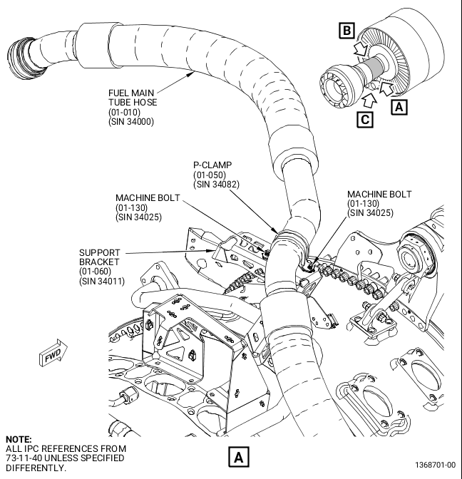
| (3) | Disconnect and attach the fuel main tube hose (01-010, 73-11-40) (SIN 34000) out of the way. Refer to Figure 1 and as follows: |
| (a) | This step is not necessary for in shop performance: Remove the splash boot from the fuel main tube at the pylon connector and disconnect the fuel main tube hose (01-010) (SIN 34000). Refer to the GEnx-1B Boeing 787 AMM, DMC-B787-A-G71-00-00-10B-520A-A. |
| (b) | Remove the two machine bolts (01-130, 73-11-40) (SIN 34025) and the P-clamp (01-050) (SIN 34082) that attach the fuel main tube hose (01-010) (SIN 34000) to the support bracket (01-060) (SIN 34011). |
| (c) | Position the fuel main tube hose (01-010) (SIN 34000) away from the FSV (01-010, 73-21-30) (SIN 31700). |
| (d) | Put the removed components in bags and label for re-installation. |
| (4) | Install the protective covers to the thrust links as follows: |
| (a) | Install commercially available material to protect the forward halves of the two thrust links from impacts, dents, and scratches from hand tools and hardware during removal and installation processes. |
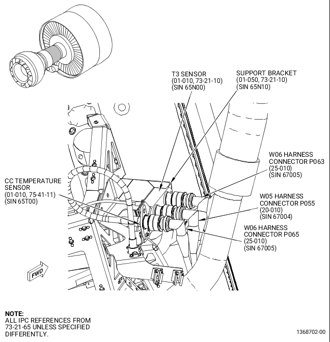
| (5) | Disconnect the W05 harness (20-010, 73-21-65) (SIN 67004) and W06 harness (25-010) (SIN 67005) as follows. Refer to Figure 2. |
| CAUTION: |
|
| CAUTION: |
|
| CAUTION: |
|
| (a) | Disconnect the W06 harness (25-010) (SIN 67005) electrical connector P063 from the T3 sensor (01-010, 73-21-10) (SIN 65N00) and electrical connector P065 from the core compartment (CC) temperature sensor (01-010, 75-41-11) (SIN 65T00) located at the support bracket (01-050, 73-21-10) (SIN 65N10). |
| (b) | Disconnect the W05 harness (20-010, 73-21-65) (SIN 67004) electrical connector P055 from the T3 sensor (01-010, 73-21-10) (SIN 65N00) at the support bracket (01-050) (SIN 65N10). |
| (c) | Install protective covers to the exposed electrical connections. |
| (d) | Place the removed harness leads away from the FSV (01-010, 73-21-30) (SIN 31700) area. |
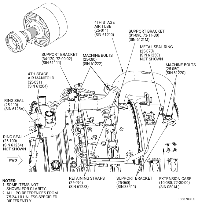
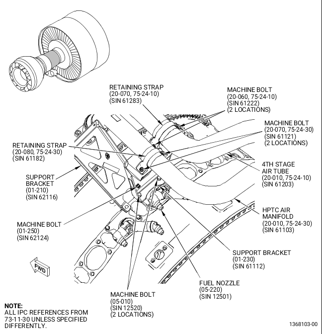
| (6) | Remove the 4th stage air tube (25-011, 75-24-10) (SIN 61200) as follows. Refer to Figure 3. |
| WARNING: |
|
| (a) | Apply C02-053 penetrating oil or equivalent to the four machine bolts (25-050) (SIN 61220) that attach the forward end of the 4th stage air tube (25-011) (SIN 61200) to the compressor case before the bolts are removed. |
| (b) | Remove the ring seal (25-110) (SIN 6128A) that attaches the aft end of the 4th stage air tube (25-011) (SIN 61200) to 4th stage air manifold (25-031) (SIN 61204). |
| (c) | Remove the four machine bolts (25-080) (SIN 61222) and two retaining straps (25-090) (SIN 61283) that attach the 4th stage air tube (25-011) (SIN 61200) to the support bracket (34-120, 72-00-02) (SIN 61111) and to the support bracket (01-090, 73-11-30) (SIN 6121M). |
| WARNING: |
|
| (d) | Break the torque on four machine bolts (25-050, 75-24-10) (SIN 61220) that attach the forward end of the 4th stage air tube (25-011) (SIN 61200) to the compressor case and apply C02-053 penetrating oil or equivalent again to the bolt threads before the bolts are removed. |
| 1 | Remove the four machine bolts (25-050) (SIN 61220) that attach the forward end of the 4th stage air tube (25-011) (SIN 61200) to the compressor case. |
| (e) | Remove the 4th stage air tube (25-011) (SIN 61200). |
| NOTE: |
|
| (f) | Remove and discard the metal seal ring (25-070) (SIN 61250) and the ring seal (25-100) (SIN 61254) from the engine. Apply protective covers to exposed openings. |
| (g) | Store the remaining components in bags for re-installation. |
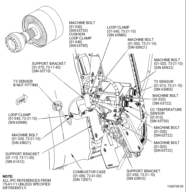
| (7) | Remove the CC temperature sensor (01-010, 75-41-11) (SIN 65T00) and the T3 sensor (01-010, 73-21-10) (SIN 65N00) from the 4:00 o'clock position of the compressor case as follows. Refer to Figure 4. |
| CAUTION: |
|
| CAUTION: |
|
| CAUTION: |
|
| (b) | Remove the machine bolt (01-030, 75-41-11) (SIN 65T20) and the cushion loop clamp (01-040) (SIN 65T80) that attach the CC temperature sensor (01-010) (SIN 65T00) lead to the support bracket (01-070, 73-11-40) (SIN 65T10). |
| (c) | Remove the four machine bolts (01-020, 75-41-11) (SIN 65T22) that attach the CC temperature sensor (01-010) (SIN 65T00) to the support bracket (01-050, 73-21-10) (SIN 65N10) and remove the CC temperature sensor (01-010, 75-41-11) (SIN 65T00) from the engine. |
| (d) | Remove the two machine bolts (01-030, 73-21-10) (SIN 65N21) that attach the T3 sensor (01-010) (SIN 65N00) lead to the support bracket (01-110, 73-11-30) (SIN 61A12) in two places with two loop clamps (01-040, 73-21-10) (SIN 65N80). |
| WARNING: |
|
| (e) | Apply C02-053 penetrating oil or equivalent to the T3 sensor B-nut fitting at the boss on the combustor case before the B-nut is removed. |
| (f) | Disconnect the T3 sensor (01-010) (SIN 65N00) lead from the boss on the combustor case (01-080, 72-41-00) (SIN 12001). |
| (g) | Remove the two machine bolts (01-020, 73-21-10) (SIN 65N22) that attach the T3 sensor (01-010) (SIN 65N00) to the support bracket (01-050) (SIN 65N10). |
| (h) | Remove the T3 sensor (01-010) (SIN 65N00) from the engine. |
| (i) | Store all components in bags and label them for re-installation. |
| (j) | Install protective covers on all exposed sensor and harness connections. |
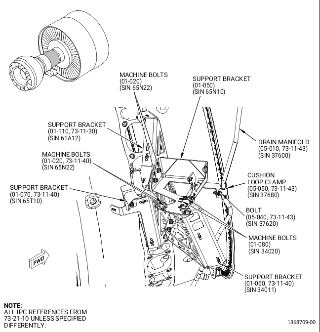
| (8) | Remove the support bracket (01-050) (SIN 65N10) as follows. Refer to Figure 5 and Figure 11. |
| CAUTION: |
|
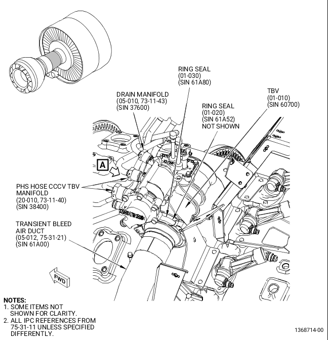
| (a) | Disconnect the drain manifold (05-010, 73-11-43) (SIN 37600) B-nut that attaches the drain manifold to the transient bleed valve (TBV) (01-010, 75-31-11) (SIN 60700). Refer to Figure 11. |
| (b) | Remove the machine bolt (05-040, 73-11-43) (SIN 37620) and the cushion loop clamp (05-050) (SIN 37680) that attach the drain manifold (05-010) (SIN 37600) to the support bracket (01-050, 73-21-10) (SIN 65N10). Refer to Figure 5. |
| (c) | Remove the two machine bolts (01-020) (SIN 65N22) that attach the support bracket (01-050) (SIN 65N10) to the support bracket (01-110, 73-11-30) (SIN 61A12). |
| (d) | Remove the two machine bolts (01-020, 73-11-40) (SIN 65N22) that attach the support bracket (01-050, 73-21-10) (SIN 65N10) to the support bracket (01-070, 73-11-40) (SIN 65T10). |
| (e) | Remove the two machine bolts (01-080, 73-21-10) (SIN 34020) that attach the support bracket (01-050) (SIN 65N10) to the support bracket (01-060, 73-11-40) (SIN 34011) and let the bracket hang loosely. |
| NOTE: |
|
| (g) | Store the removed components in bags and label them for re-installation. |
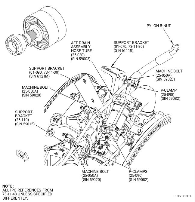
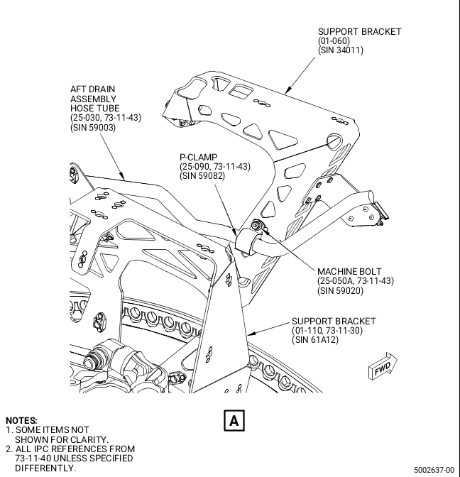
| (9) | Remove the AFT drain assembly hose tube (25-030, 73-11-43) (SIN 59003) as follows. Refer to Figure 6. |
| CAUTION: |
|
| (a) | This step is not necessary for in shop performance: Disconnect the AFT drain assembly hose tube (25-030, 73-11-43) (SIN 59003) B-nut from the pylon hanger fitting. For the removal of the AFT drain assembly hose tube (25-030) (SIN 59003) refer to the GEnx-1B Boeing 787 AMM, DMC-B787-A-G71-00-00-10B-520A-A, step C. (21). |
| (b) | Remove the three machine bolts (25-050A) (SIN 59020) and the three P-clamps (25-090) (SIN 59082) that attach the AFT drain assembly hose tube (25-030) (SIN 59003) to the support bracket (01-070, 73-11-30) (SIN 61110), support bracket (01-090) (SIN 6121M), and support bracket (25-110, 73-11-43) (SIN 59015). |
| (c) | Remove the AFT drain assembly hose tube (25-030) (SIN 59003) and support bracket (01-050, 73-21-10) (SIN 65N10) from the engine. |
| (d) | Install protective covers on all exposed openings. |
| (e) | Store the removed components in bags and label them for re-installation. |
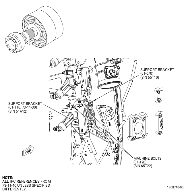
| (10) | Remove the support bracket (01-070, 73-11-40) (SIN 65T10) as follows. Refer to Figure 7. |
| (a) | Remove the two machine bolts (01-120) (SIN 65T22) that attach the support bracket (01-070) (SIN 65T10) to the support bracket (01-110, 73-11-30) (SIN 61A12). |
| (b) | Remove the support bracket (01-070, 73-11-40) (SIN 65T10) from the engine. |
| (c) | Store all components in bags and label them for re-installation. |
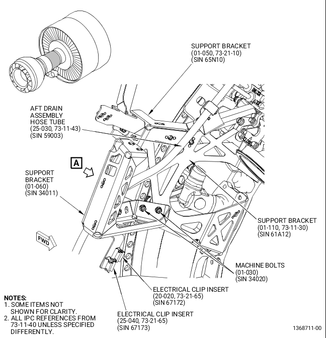
| (11) | Remove the support bracket (01-060) (SIN 34011) as follows. Refer to Figure 8. |
| (a) | Disengage the harness leads from the support bracket (01-060) (SIN 34011). Keep the electrical clip insert (20-020, 73-21-65) (SIN 67172) and the electrical clip insert (25-040) (SIN 67173) in the support bracket (01-060, 73-11-40) (SIN 34011). |
| (b) | Remove the machine bolt (25-050, 73-11-43) (SIN 59020) and the P-clamp (25-090) (SIN 59082) that attach the AFT drain assembly hose tube (25-030) (SIN 59003) to the support bracket (01-060, 73-11-40) (SIN 34011). |
| (c) | Remove the two machine bolts (01-030) (SIN 34020) that attach the support bracket (01-060) (SIN 34011) to the support bracket (01-110, 73-11-30) (SIN 61A12). |
| (d) | Remove the support bracket (01-060, 73-11-40) (SIN 34011) with the electrical clip inserts from the engine. |
| (e) | Store all components in bags and label them for re-installation. |
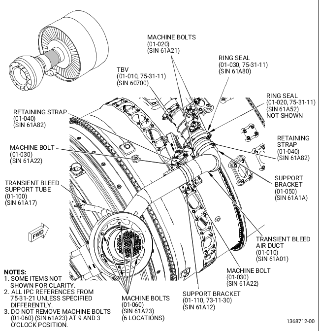
| (12) | Remove the transient bleed air duct assembly (01-010, 75-31-21) (SIN 61A01) as follows. Refer to Figure 9. |
| (a) | Remove the ring seal (01-030, 75-31-11) (SIN 61A80) that attaches the transient bleed air duct (01-010, 75-31-21) (SIN 61A01) to the TBV (01-010, 75-31-11) (SIN 60700). |
| (b) | Remove the two machine bolts (01-020, 75-31-21) (SIN 61A21) and the retaining strap (01-040) (SIN 61A82) that attach the transient bleed air duct (01-010) (SIN 61A01) to the support bracket (01-050) (SIN 61A1A). |
| (c) | Remove the two machine bolts (01-030) (SIN 61A22) and the retaining strap (01-040) (SIN 61A82) that attach the transient bleed air duct (01-010) (SIN 61A01) to the support bracket (01-110, 73-11-30) (SIN 61A12). |
| (d) | Remove the four machine bolts (01-060, 75-31-21) (SIN 61A23) that attach the transient bleed air duct assembly to the transient bleed support tube (01-100) (SIN 61A17). Do not remove the machine bolts at the 9 and 3 o'clock positions. |
| (e) | Remove the transient bleed air duct assembly (01-010) (SIN 61A01) from the engine. |
| (f) | Remove and discard the ring seal (01-020, 75-31-11) (SIN 61A52) from the TBV (01-010) (SIN 60700). |
| (g) | Apply protective covers to all exposed openings. |
| (h) | Store the components in bags and label them for re-installation. |
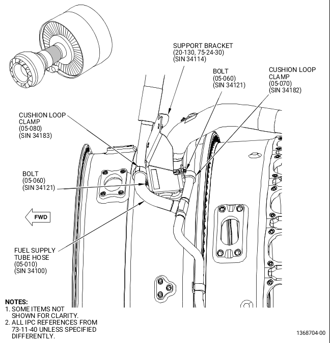
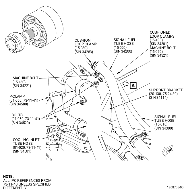
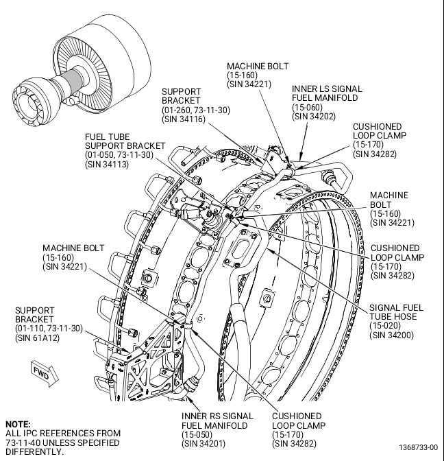
| (13) | Remove the 7th stage manifold (20-020, 75-24-30) (SIN 61100) and support bracket (20-130) (SIN 34114) as follows. Refer to Figure 10. |
| WARNING: |
|
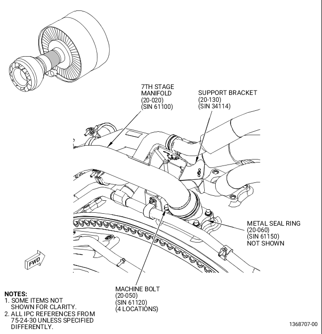
| (a) | Apply C02-053 penetrating oil or equivalent to the four machine bolts (20-050) (SIN 61120) that attach the forward end of the 7th stage manifold (20-020) (SIN 61100) to the compressor case before the bolts are removed. |
| (b) | Break the torque on four machine bolts (20-050) (SIN 61120) that attach the forward end of the 7th stage manifold (20-020) (SIN 61100) to the compressor case and apply C02-052 penetrating oil or equivalent again to the bolt threads before the bolts are removed. |
| 1 | Remove the four machine bolts (20-050) (SIN 61120) that attach the forward end of the 7th stage manifold (20-020) (SIN 61100) to the compressor case and support bracket (20-130) (SIN 34114) to the top of the 7th stage manifold (20-020) (SIN 61100) mounting flange. |
| NOTE: |
|
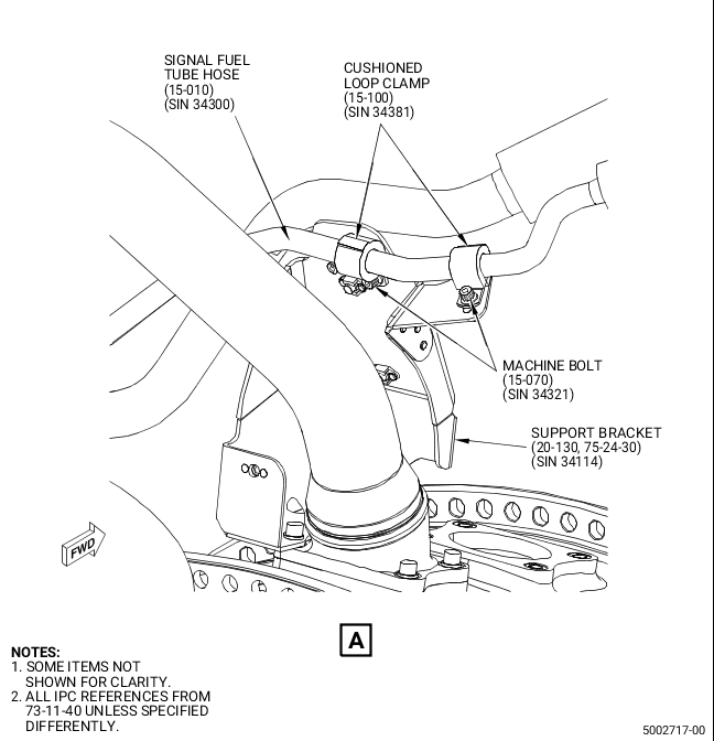
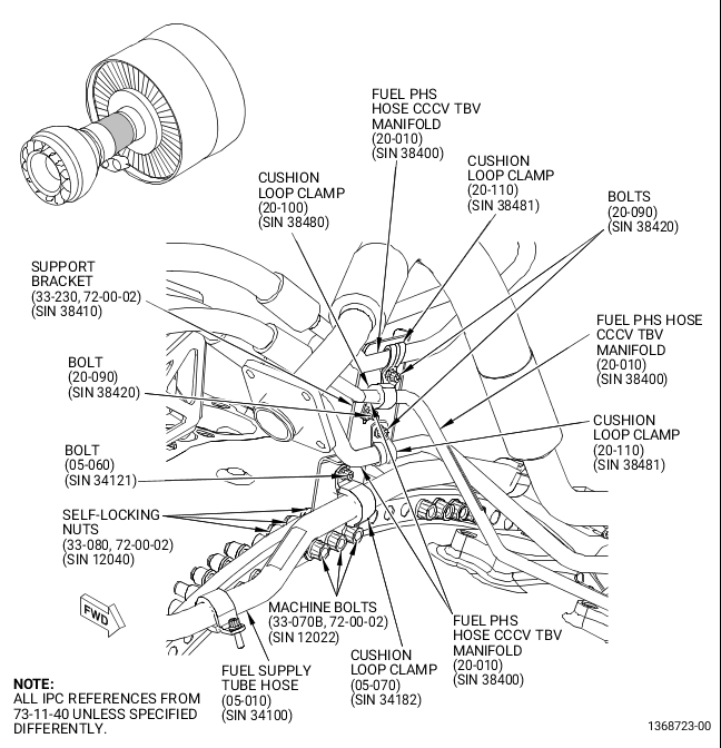
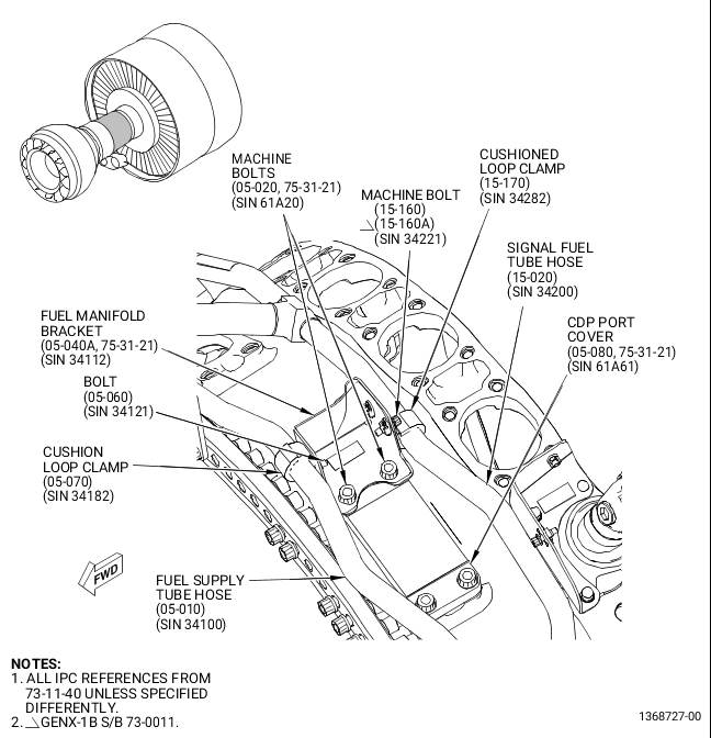
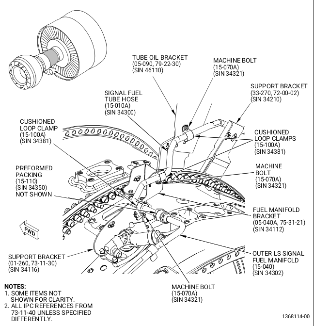
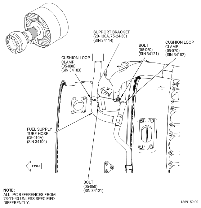
| (c) | Remove the cushion loop clamp (05-070, 73-11-40) (SIN 34182) and one machine bolt (05-060) (SIN 34121) that attach the fuel supply tube hose (05-010) (SIN 34100) to the aft face of the support bracket (20-130, 75-24-30) (SIN 34114). |
| (d) | Remove the cushion loop clamp (05-080, 73-11-40) (SIN 34183) and one machine bolt (05-060) (SIN 34121) that attach the fuel supply tube hose (05-010) (SIN 34100) to the forward face of the support bracket (20-130, 75-24-30) (SIN 34114). |
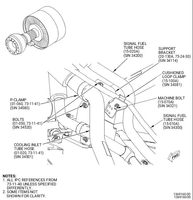
| (e) | Remove the cushion loop clamp (15-080, 73-11-40) (SIN 34283) and the machine bolt (15-160) (SIN 34221) that attach the signal fuel tube hose (15-020) (SIN 34200) to the forward face of the support bracket (20-130, 75-24-30) (SIN 34114). |
| (f) | Discard the cushioned loop clamp (15-080, 73-11-40) (SIN 34283) and machine bolt (15-160) (SIN 34221). |
| (g) | Remove the P-clamp (01-060, 73-11-41) (SIN 34580) and the two machine bolts (01-050) (SIN 34520) that attach the cooling inlet tube hose (01-020) (SIN 34501) to the forward face of the support bracket (20-130, 75-24-30) (SIN 34114). |
| (h) | Remove the two cushioned loop clamps (15-100, 73-11-40) (SIN 34381) and the two machine bolts (15-070) (SIN 34321) that attach the signal fuel tube hose (15-010) (SIN 34300) to the aft face of support bracket (20-130, 75-24-30) (SIN 34114). |
| (i) | Discard one cushioned loop clamp (15-100, 73-11-40) (SIN 34381) and one machine bolt (15-070) (SIN 34321). |
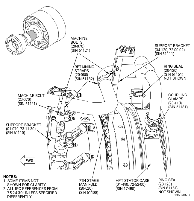
| (j) | Remove two coupling clamps (20-110, 75-24-30) (SIN 61181) that attach the aft end of the 7th stage manifold (20-020) (SIN 61100) to HPT case (01-490, 72-52-00) (SIN 174B0). |
| (k) | Remove the four machine bolts (20-070, 75-24-30) (SIN 61121) and the two retaining straps (20-080) (SIN 61182) that attach the 7th stage manifold (20-020) (SIN 61100) to the support bracket (34-120, 72-00-02) (SIN 61111) and support bracket (01-070, 73-11-30) (SIN 61110). |
| (l) | Remove the 7th stage manifold (20-020, 75-24-30) (SIN 61100), the two ring seals (20-120) (SIN 61151), the metal seal ring (20-060) (SIN 61150), and the support bracket (20-130) (SIN 34114) from the engine. |
| (m) | Ring seals (20-120) (SIN 61151), metal seal ring (20-060) (SIN 61150), and support bracket (20-130) (SIN 34114) will be replaced. Store the remaining components in bags and label them for re-installation. |
| (14) | Remove the TBV (01-010, 75-31-11) (SIN 60700) as follows. Refer to Figure 11. |
| CAUTION: |
|
| CAUTION: |
|
| (a) | Disconnect the W05 harness (20-010, 73-21-65) (SIN 67004) electrical connector P058 and the W06 harness (25-010) (SIN 67005) electrical connector P066 from the TBV (01-010, 75-31-11) (SIN 60700). |
| CAUTION: |
|
| (b) | Put a container to catch the liquid, then disconnect the drain manifold (05-010, 73-11-43) (SIN 37600) B-nut and the fuel PHS hose CCCV TBV manifold (20-010, 73-11-40) (SIN 38400) B-nut from the TBV (01-010, 75-31-11) (SIN 60700). The drain manifold (05-010, 73-11-43) (SIN 37600) can be removed to help with the disassembly. |
| (c) | Remove the ring seal (01-030) (SIN 61A80) and the TBV (01-010) (SIN 60700) from the engine. |
| NOTE: |
|
| (d) | Remove and discard the ring seal (01-020) (SIN 61A52), the preformed packing (20-080, 73-11-40) (SIN 38451), and the preformed packing (20-070) (SIN 38450). |
| (e) | Apply protective covers to all exposed openings. |
| (f) | Store the remaining components in bags and label them for re-installation. |
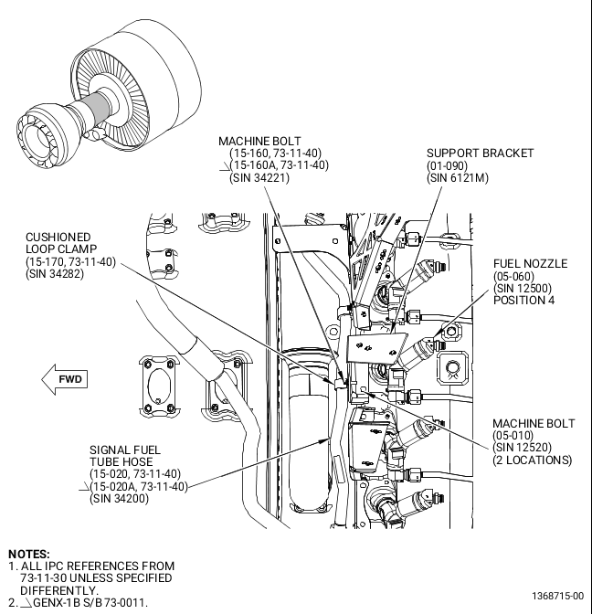
| (15) | Remove the support bracket (01-090, 73-11-30) (SIN 6121M) as follows. Refer to Figure 12. |
| WARNING: |
|
| (a) | Apply C02-053 penetrating oil or equivalent to the two machine bolts (05-010) (SIN 12520) before the bolts are removed. |
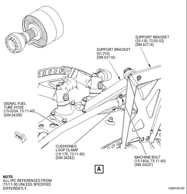
| (b) | Remove the machine bolt (15-160, 73-11-40) (SIN 34221) and the cushioned loop clamp (15-170) (SIN 34282) that attach the signal fuel tube hose (15-020) (SIN 34200) to the support bracket (01-090, 73-11-30) (SIN 6121M). |
| (c) | Remove the two machine bolts (05-010) (SIN 12520) that attach the support bracket (01-090) (SIN 6121M) to the fuel nozzle (05-060) (SIN 12500) at fuel nozzle position 4 aft looking forward (ALF). |
| (d) | Remove the support bracket (01-090) (SIN 6121M) from the engine. |
| (e) | Store all components in bags and label them for re-installation. |
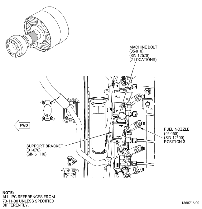
| (16) | Remove the support bracket (01-070, 73-11-30) (SIN 61110) as follows. Refer to Figure 13. |
| WARNING: |
|
| (a) | Apply C02-053 penetrating oil or equivalent to the two machine bolts (05-010) (SIN 12520) before the bolts are removed. |
| (b) | Remove the two machine bolts (05-010) (SIN 12520) that attach the support bracket (01-070) (SIN 61110) to the fuel nozzle (05-050) (SIN 12500) at fuel nozzle position 3 ALF. |
| (c) | Remove the support bracket (01-070) (SIN 61110) from the engine. |
| (d) | Store all components in bags and label them for re-installation. |
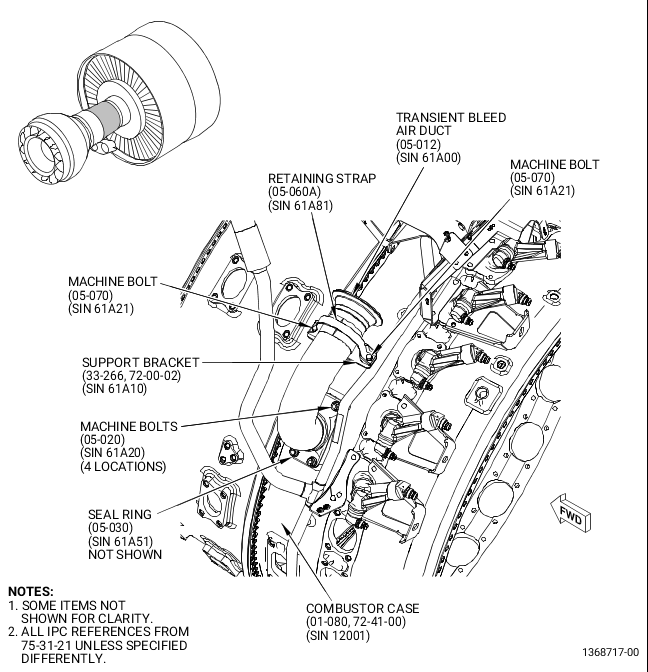
| (17) | Remove the transient bleed air duct (05-012, 75-31-21) (SIN 61A00) as follows. Refer to Figure 14. |
| WARNING: |
|
| (a) | Apply C02-053 penetrating oil or equivalent to the machine bolts (05-020) (SIN 61A20) that attach the transient bleed air duct (05-012) (SIN 61A00) to the combustor case before the bolts are removed. |
| (b) | Remove the two machine bolts (05-070) (SIN 61A21) and the retaining strap (05-060A) (SIN 61A81) that attach the transient bleed air duct (05-012) (SIN 61A00) to the transient bleed air bracket (support bracket) (33-266, 72-00-02) (SIN 61A10). |
| WARNING: |
|
| (c) | Break the torque on four machine bolts (05-020) (SIN 61A20) that attach the transient bleed air duct (05-012) (SIN 61A00) to the combustor case and apply C02-053 penetrating oil or equivalent again to the bolt threads before the bolts are removed. |
| 1 | Remove the four machine bolts (05-020) (SIN 61A20) that attach the transient bleed air duct (05-012) (SIN 61A00) to the combustor case (01-080, 72-41-00) (SIN 12001). |
| (d) | Remove the transient bleed air duct (05-012, 75-31-21) (SIN 61A00) from the engine. |
| (e) | Remove and discard the seal ring (05-030) (SIN 61A51) from the engine. |
| (f) | Apply protective covers to all exposed openings. |
| (g) | Store the remaining components in bags and label them for re-installation. |
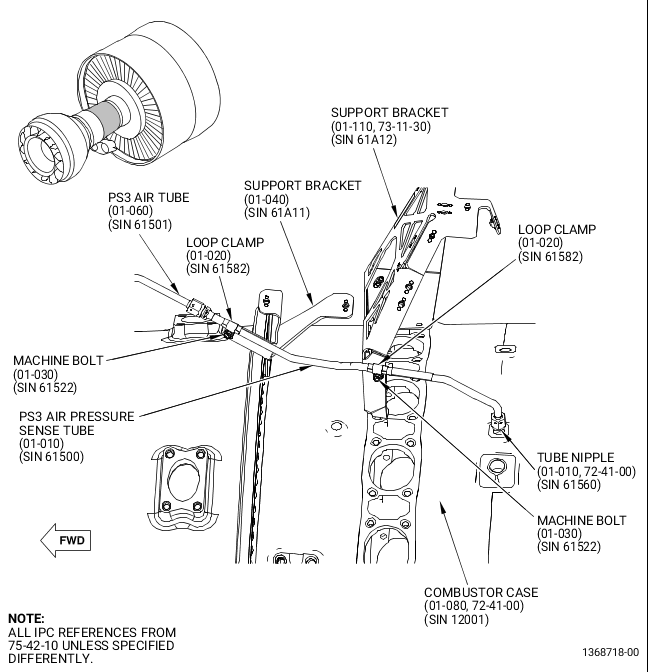
| (18) | Remove the PS3 air pressure sense tube (01-010, 75-42-10) (SIN 61500) as follows. Refer to Figure 15. |
| WARNING: |
|
| (a) | Apply C02-053 penetrating oil or equivalent to the B-nut that attaches the PS3 air pressure sense tube (01-010) (SIN 61500) to the tube nipple (01-010 )(SIN 61560) on the combustor case (01-080) (SIN 12001). |
| (b) | Remove the C10-071 safety wire or C10-143 safety cable that attach the PS3 air pressure sense tube (01-010) (SIN 61500) B-nuts to the tube nipple (01-010, 72-41-00) (SIN 61560) on the combustor case (01-080) (SIN 12001) and to the PS3 air tube (01-060, 75-42-10) (SIN 61501). |
| (c) | Remove the two machine bolts (01-030) (SIN 61522) and the two loop clamps (01-020) (SIN 61582) that attach the PS3 air pressure sense tube (01-010) (SIN 61500) to the support bracket (01-040) (SIN 61A11) and support bracket (01-110, 73-11-30) (SIN 61A12). |
| CAUTION: |
|
| (d) | Disconnect the B-nuts that attach the PS3 air pressure sense tube (01-010, 75-42-10) (SIN 61500) to the tube nipple (01-010, 72-41-00) (SIN 61560) on the combustor case (01-080) (SIN 12001) and to the PS3 air tube (01-060, 75-42-10) (SIN 61501). |
| (e) | Remove the PS3 air pressure sense tube (01-010) (SIN 61500). |
| (f) | Install protective covers to all exposed openings. |
| (g) | Store all components in bags and label them for re-installation. |
| (19) | Remove the transient bleed air bracket (33-266, 72-00-02) (SIN 61A10) as follows. Refer to Figure 16. |
| (a) | Remove the four self-locking nuts (33-080, 72-00-02) (SIN 12040) that attach the transient bleed air bracket (33-266) (SIN 61A10) to the aft face of the combustor case (01-080, 72-41-00) (SIN 12001) forward flange. |
| (b) | Remove the transient bleed air bracket (33-266, 72-00-02) (SIN 61A10) from the engine. Do not remove the four machine bolts (33-070B) (SIN 12022). |
| (c) | Discard the self-locking nuts. Keep the bracket for re-installation. |
| (20) | Remove the signal fuel tube hose (15-010, 73-11-40) (SIN 34300) as follows. Refer to Figure 17. |
| NOTE: |
|
| (a) | Remove the two machine bolts (15-230) (SIN 34322) that attach the signal fuel tube hose (15-010) (SIN 34300) to the FSV (01-010, 73-21-30) (SIN 31700). |
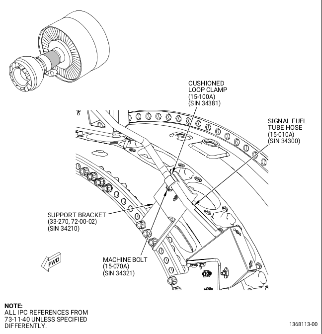
| (b) | Remove the machine bolt (15-070, 73-11-40) (SIN 34321) and the cushioned loop clamp (15-100) (SIN 34381) that attach the signal fuel tube hose (15-010) (SIN 34300) to the support bracket (33-270, 72-00-02) (SIN 34210). |
| (c) | Remove the machine bolt (15-070, 73-11-40) (SIN 34321) and the cushioned loop clamp (15-100) (SIN 34381) that attach the signal fuel tube hose (15-010) (SIN 34300) to the tube oil bracket (05-090, 79-22-30) (SIN 46110). |
| (d) | Remove the machine bolt (15-070, 73-11-40) (SIN 34321) and the cushioned loop clamp (15-100) (SIN 34381) that attach the signal fuel tube hose (15-010) (SIN 34300) to the aft face of fuel manifold bracket (05-040A, 75-31-21) (SIN 34112). |
| (e) | Remove the machine bolt (15-070, 73-11-40) (SIN 34321) and the cushioned loop clamp (15-100) (SIN 34381) that attach the signal fuel tube hose (15-010) (SIN 34300) to the support bracket (01-260, 73-11-30) (SIN 34116). |
| CAUTION: |
|
| (f) | Disconnect the signal fuel tube hose (15-010, 73-11-40) (SIN 34300) from the outer left side (LS) signal fuel manifold (15-040) (SIN 34302). |
| (g) | Disengage the signal fuel tube hose (15-010) (SIN 34300) from the FSV (01-010, 73-21-30) (SIN 31700) and remove it from the engine. |
| (h) | If necessary, record the serial number from the discarded temperature sensor (01-010, 73-31-05) (SIN 65T01) for engine documentation. |
| (i) | The signal fuel tube hose (15-010, 73-11-40) (SIN 34300) and the two preformed packings (15-090) (SIN 34351) will be replaced later. Keep all the cushioned loop clamps and bolts for re-installation. |
| (j) | Remove the preformed packing (15-110) (SIN 34350) from the outer LS signal fuel manifold (15-040) (SIN 34302) and install protective covers to all exposed openings. |
| (k) | Discard the signal fuel tube hose (15-010) (SIN 34300), two preformed packings (15-090) (SIN 34351), and the two machine bolts (15-230) (SIN 34322). |
| (l) | Store the remaining components in bags and label them for re-installation. |
| (21) | Remove the support bracket (33-230, 72-00-02) (SIN 38410) as follows. Refer to Figure 18. |
| (a) | Remove the machine bolt (05-060, 73-11-40) (SIN 34121) and the cushion loop clamp (05-070) (SIN 34182) that attach the fuel supply tube hose (05-010) (SIN 34100) to the support bracket (33-230, 72-00-02) (SIN 38410). |
| (b) | Remove the three machine bolts (20-090, 73-11-40) (SIN 38420), the two cushion loop clamps (20-110) (SIN 38481), and the cushion loop clamp (20-100) (SIN 38480) that attach the three tubes of the fuel PHS hose CCCV TBV manifold (20-010) (SIN 38400) to the support bracket (33-230, 72-00-02) (SIN 38410). |
| (c) | Remove the three self-locking nuts (33-080) (SIN 12040) and the three machine bolts (33-070B) (SIN 12022) and remove the support bracket (33-230) (SIN 38410) from the engine. |
| (d) | Discard the three self-locking nuts (33-080) (SIN 12040). |
| (e) | Store the remaining components in bags and label them for re-installation. |
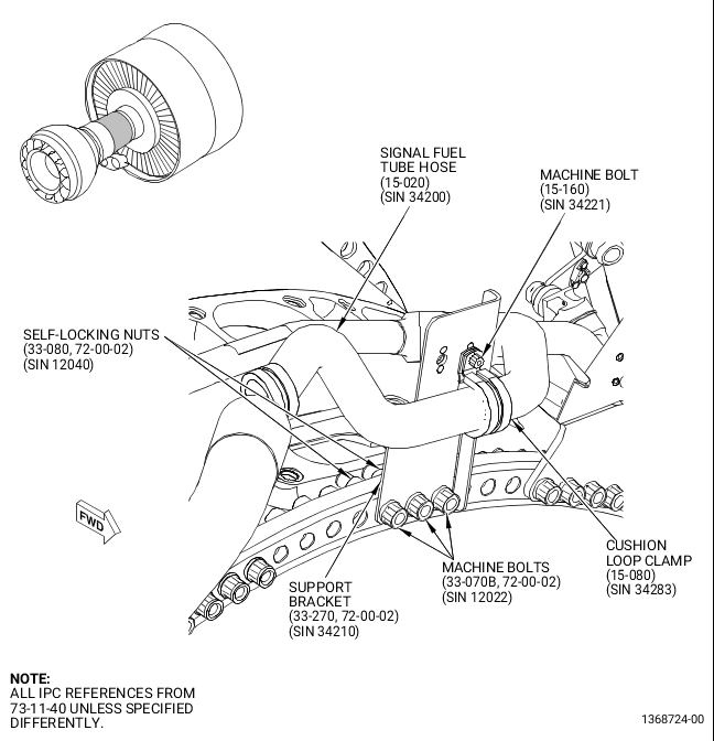
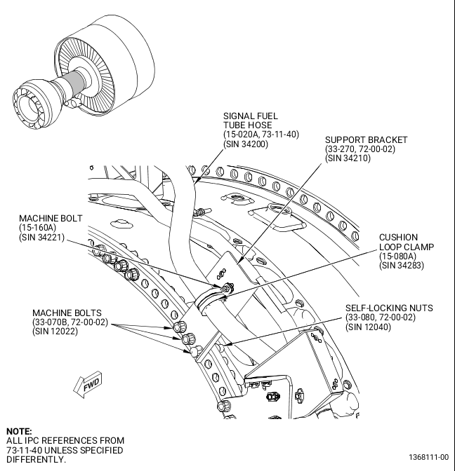
| (22) | Remove the support bracket (33-270, 72-00-02) (SIN 34210) as follows. Refer to Figure 19. |
| (a) | Remove the machine bolt (15-160, 73-11-40) (SIN 34221) and the cushion loop clamp (15-080) (SIN 34283) that attach the signal fuel tube hose (15-020) (SIN 34200) to the support bracket (33-270, 72-00-02) (SIN 34210). |
| (b) | Remove the three self-locking nuts (33-080) (SIN 12040) and the three machine bolts (33-070B) (SIN 12022) and remove the support bracket (33-270) (SIN 34210) from the engine. |
| (c) | Discard the three self-locking nuts (33-080) (SIN 12040). |
| (d) | Store the remaining components in bags and label them for re-installation. |
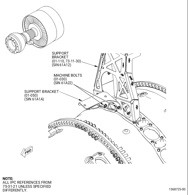
| (23) | Remove the support bracket (01-050, 75-31-21) (SIN 61A1A) as follows. Refer to Figure 20. |
| (a) | Remove the two machine bolts (01-030) (SIN 61A22) that attach the support bracket (01-050) (SIN 61A1A) to the support bracket (01-110, 73-11-30) (SIN 61A12). |
| (b) | Remove the support bracket (01-050, 75-31-21) (SIN 61A1A) from the engine. |
| (c) | Store all components in bags and label them for re-installation. |
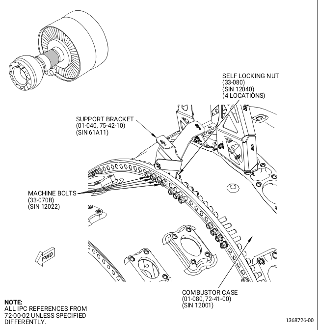
| (24) | Remove the support bracket (01-040, 75-42-10) (SIN 61A11) as follows. Refer to Figure 21. |
| (a) | Remove the four self-locking nuts (33-080, 72-00-02) (SIN 12040) that attach the support bracket (01-040, 75-42-10) (SIN 61A11) to the aft face of the combustor case (01-080, 72-41-00) (SIN 12001) forward flange. |
| (b) | Discard the four self-locking nuts (33-080) (SIN 12040). |
| (c) | Do not remove the four machine bolts (33-070, 72-00-02) (SIN 12022) from the engine. |
| (d) | Remove the support bracket (01-040, 75-42-10) (SIN 61A11) from the engine. |
| (e) | Store the bracket in a bag for re-installation. |
| (25) | Remove the fuel manifold bracket (05-040A, 75-31-21) (SIN 34112) as follows. Refer to Figure 22. |
| (a) | Remove the machine bolt (15-160, 73-11-40) (SIN 34221) and the cushioned loop clamp (15-170) (SIN 34282) that attach the signal fuel tube hose (15-020) (SIN 34200) to the aft face of the fuel manifold bracket (05-040A, 75-31-21) (SIN 34112). |
| (b) | Remove the machine bolt (05-060, 73-11-40) (SIN 34121) and the cushion loop clamp (05-070) (SIN 34182) that attach the fuel supply tube hose (05-010) (SIN 34100) to the forward face of the fuel manifold bracket (05-040A, 75-31-21) (SIN 34112). |
| (c) | Remove the two machine bolts (05-020) (SIN 61A20) that attach the fuel manifold bracket (05-040A) (SIN 34112) to the CDP port cover (05-080) (SIN 61A61). |
| (d) | Remove the fuel manifold bracket (05-040A) (SIN 34112) from the engine. |
| (e) | Store all components in bags and label them for re-installation. |
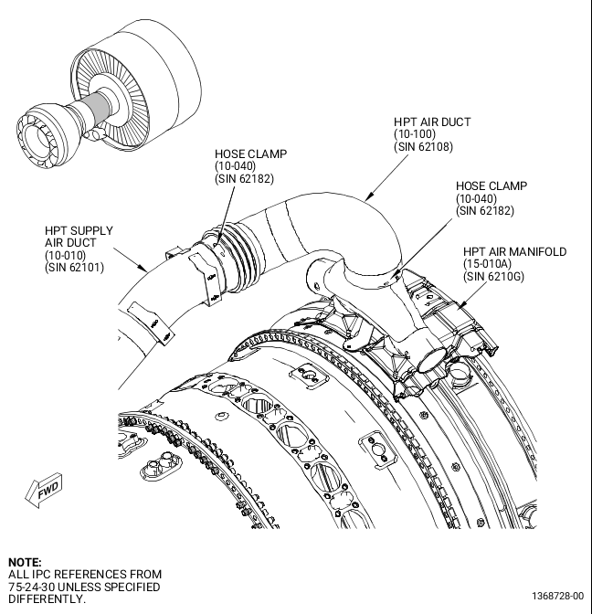
| (26) | Remove the HPT air duct (10-100, 75-24-30) (SIN 62108) from the left side of the engine as follows. Refer to Figure 23. |
| (a) | Loosen the two hose clamps (10-040) (SIN 62182) that attach the HPT air duct (10-100) (SIN 62108) to the HPT air manifold (15-010A) (SIN 6210G) and the HPT supply air duct (10-010) (SIN 62101). |
| (b) | Remove the HPT air duct (10-100) (SIN 62108) and the two hose clamps (10-040) (SIN 62182) from the engine. |
| (c) | Install protective covers on exposed openings. |
| (d) | Store all components in bags and label them for re-installation. |
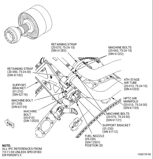
| (27) | Remove the machine bolt (01-250, 73-11-30) (SIN 62124) that attaches the support bracket (01-230) (SIN 61112) to the support bracket (01-210) (SIN 62116). Refer to Figure 24. |
| (28) | Remove the support bracket (01-190) (SIN 6221B) from the left side of the engine as follows. Refer to Figure 25. |
| WARNING: |
|
| (a) | Apply C02-053 penetrating oil or equivalent to the two machine bolts (05-010) (SIN 12520) before the bolts are removed. |
| (b) | Remove the two machine bolts (01-100, 75-24-40) (SIN 61B22) and the retaining strap (01-090) (SIN 61B80) that attach the eductor air tube (01-030) (SIN 61B01) to the support bracket (01-190, 73-11-30) (SIN 6221B). |
| (c) | Remove the machine bolt (15-160, 73-11-40) (SIN 34221) and the cushioned loop clamp (15-170) (SIN 34282) that attach the signal fuel tube hose (15-020) (SIN 34200) to the support bracket (01-190, 73-11-30) (SIN 6221B). |
| (d) | Remove the bolt (05-060, 73-11-40) (SIN 34121) and the cushion loop clamp (05-070) (SIN 34182) that attach the fuel supply tube hose (05-010) (SIN 34100) to the support bracket (01-190, 73-11-30) (SIN 6221B). |
| (e) | Remove the two machine bolts (10-090, 75-24-10) (SIN 62220) that attach the support bracket (01-190, 73-11-30) (SIN 6221B) to the support bracket (10-100, 75-24-10) (SIN 6221C). |
| (f) | Remove two machine bolts (05-010, 73-11-30) (SIN 12520) that attach the support bracket (01-190) (SIN 6221B) to the fuel nozzle (05-200) (SIN 12501) at fuel nozzle position 18 ALF. |
| (g) | Remove the support bracket (01-190) (SIN 6221B) from the engine. |
| (h) | Store all components in bags and label them for re-installation. |
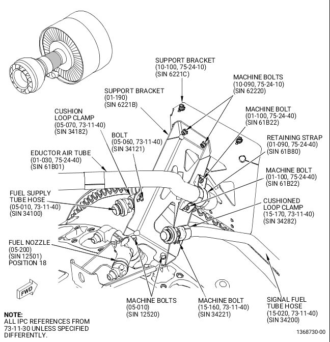
| (29) | Remove the support bracket (01-210, 73-11-30) (SIN 62116) from the left side of the engine as follows. Refer to Figure 26. |
| WARNING: |
|
| (a) | Apply C02-053 penetrating oil or equivalent to one machine bolt (05-010) (SIN 12520) before the bolt is removed. |
| (b) | Remove the machine bolt (15-160, 73-11-40) (SIN 34221) and the cushioned loop clamp (15-170) (SIN 34282) that attach the signal fuel tube hose (15-020) (SIN 34200) to the support bracket (01-210, 73-11-30) (SIN 62116). |
| (c) | Remove the machine bolt (05-010) (SIN 12520) that attaches the support bracket (01-210) (SIN 62116) to the fuel nozzle (05-210) (SIN 12501) at fuel nozzle position 19 ALF. |
| (d) | Remove the two machine bolts (33-090, 72-00-02) (SIN 62123) that attach the support bracket (01-210, 73-11-30) (SIN 62116) to the support bracket (33-130, 72-00-02) (SIN 62114). |
| (e) | Remove the support bracket (01-210, 73-11-30) (SIN 62116) from the engine. |
| (f) | Store all components in bags and label them for re-installation. |
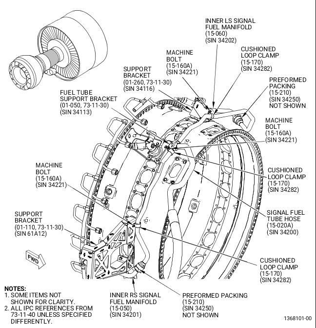
| (30) | Remove the signal fuel tube hose (15-020, 73-11-40) (SIN 34200) as follows. Refer to Figure 27. |
| (a) | Remove the three machine bolts (15-160) (SIN 34221) and the three cushioned loop clamps (15-170) (SIN 34282) that attach the signal fuel tube hose (15-020) (SIN 34200) to the support bracket (01-260, 73-11-30) (SIN 34116), fuel tube support bracket (01-050) (SIN 34113), and support bracket (01-110) (SIN 61A12). |
| CAUTION: |
|
| (b) | Remove the C10-071 safety wire or C10-143 safety cable that attach the inner RS signal fuel manifold (15-050, 73-11-40) (SIN 34201) B-nut to the signal fuel tube hose (15-020) (SIN 34200) and disconnect the B-nut. |
| (c) | Remove the C10-071 safety wire or C10-143 safety cable that secure the inner LS signal fuel manifold (15-060) (SIN 34202) B-nut to the signal fuel tube hose (15-020) (SIN 34200) and disconnect the B-nut. |
| CAUTION: |
|
| (d) | Remove the four machine bolts (15-220) (SIN 34222) that attach the signal fuel tube hose (15-020) (SIN 34200) to the FSV (01-010, 73-21-30) (SIN 31700). Discard two machine bolts (15-220, 73-11-40) (SIN 34222) and keep two for re-installation. |
| (e) | Remove and discard the signal fuel tube hose (15-020, 73-11-40) (SIN 34200) from the engine. Two preformed packings (15-210) (SIN 34250) are discarded with the signal fuel tube hose (15-020) (SIN 34200). |
| (f) | Remove and discard the preformed packing (15-150) (SIN 34251) and preformed packing (15-120) (SIN 34252). |
| (g) | Install protective covers on all exposed openings. |
| (h) | Store the remaining components in bags and label them for re-installation. |
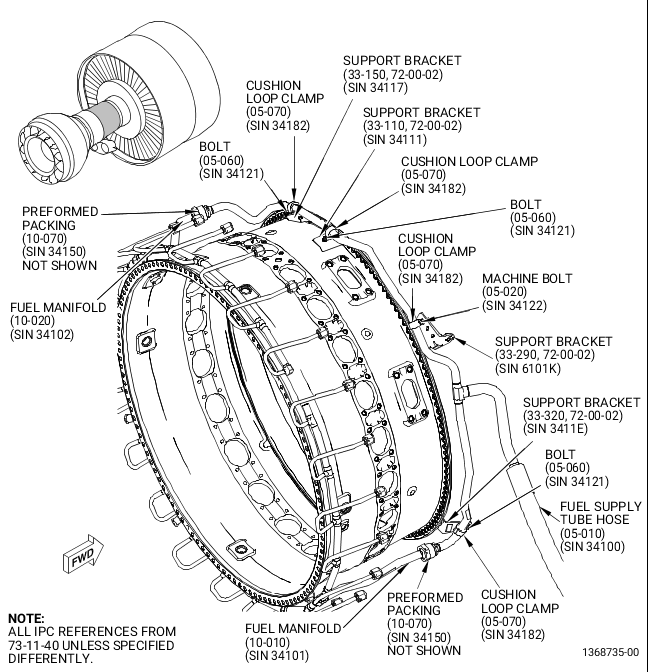
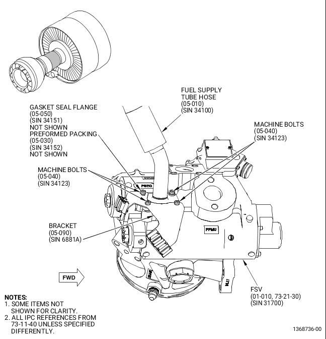
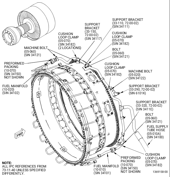
| (31) | Remove the fuel supply tube hose (05-010, 73-11-40) (SIN 34100) and bracket (05-090) (SIN 6881A) as follows. Refer to Figure 28. |
| (a) | Remove the two machine bolts (05-060) (SIN 34121) and the cushion loop clamps (05-070) (SIN 34182) that attach the fuel supply tube hose (05-010) (SIN 34100) to the support bracket (33-320, 72-00-02) (SIN 3411E) and support bracket (33-110) (SIN 34111). |
| (b) | Remove the machine bolt (05-020, 73-11-40) (SIN 34122) and the cushion loop clamp (05-070) (SIN 34182) that attach the fuel supply tube hose (05-010) (SIN 34100) to the support bracket (33-290, 72-00-02) (SIN 6101K). |
| (c) | Remove the bolt (05-060, 73-11-40) (SIN 34121) and cushion loop clamp (05-070) (SIN 34182) that attach the fuel supply tube hose (05-010) (SIN 34100) to the support bracket (33-150, 72-00-02) (SIN 34117). |
| CAUTION: |
|
| (d) | Remove the C10-071 safety wire or C10-143 safety cable that attach the fuel manifold (10-010, 73-11-40) (SIN 34101) B-nut with the fuel supply tube hose (05-010) (SIN 34100), and disconnect the B-nut. |
| (e) | Remove the C10-071 safety wire or C10-143 safety cable that attach the fuel manifold (10-020) (SIN 34102) B-nut with the fuel supply tube hose (05-010) (SIN 34100), and disconnect the B-nut. |
| CAUTION: |
|
| (f) | Remove the four machine bolts (05-040) (SIN 34123) that attach the fuel supply tube hose (05-010) (SIN 34100) and bracket (05-090) (SIN 6881A) to the FSV (01-010, 73-21-30) (SIN 31700). |
| (g) | Remove and discard the fuel supply tube hose (05-010, 73-11-40) (SIN 34100), bracket (05-090) (SIN 6881A), electrical clip insert (25-050, 73-21-65) (SIN 67172), and electrical clip insert (20-020) (SIN 67172) from the FSV (01-010, 73-21-30) (SIN 31700). Two preformed packings (10-070, 73-11-40) (SIN 34150) are discarded with the signal fuel tube hose (15-020) (SIN 34200). |
| (h) | Remove and discard the flange seal gasket (05-050) (SIN 34151) and preformed packing (05-030) (SIN 34152). |
| (i) | Install protective covers on all the exposed openings. |
| (j) | Store the remaining components in bags and label them for re-installation. |
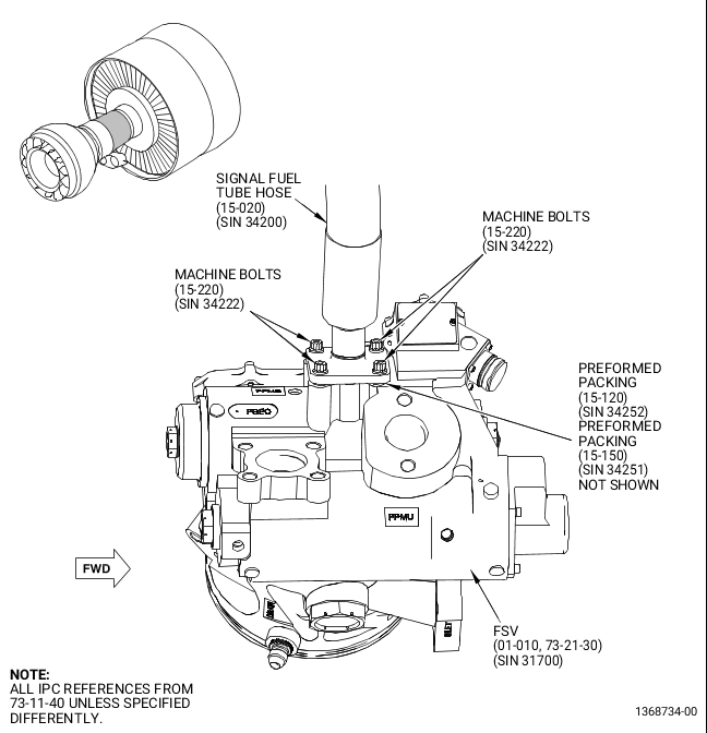
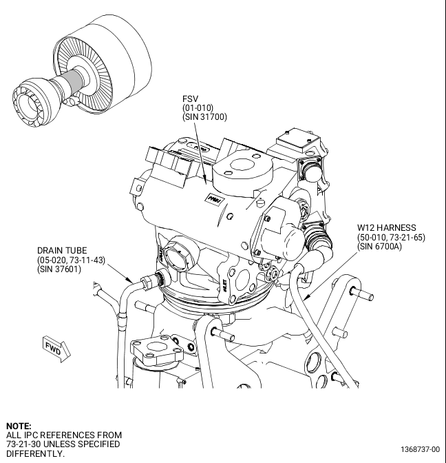
| (32) | Disconnect the drain tube (05-020, 73-11-43) (SIN 37601) and the W12 harness (50-010, 73-21-65) (SIN 6700A) lead from the FSV (01-010, 73-21-30) (SIN 31700) as follows. Refer to Figure 29. |
| CAUTION: |
|
| (a) | Disconnect the drain tube (05-020, 73-11-43) (SIN 37601) from the FSV (01-010, 73-21-30) (SIN 31700). |
| CAUTION: |
|
| CAUTION: |
|
| (b) | Remove the W12 harness (50-010, 73-21-65) (SIN 6700A) lead from the FSV (01-010, 73-21-30) (SIN 31700). |
| (c) | Install protective covers on all exposed orifices and electrical connections. |
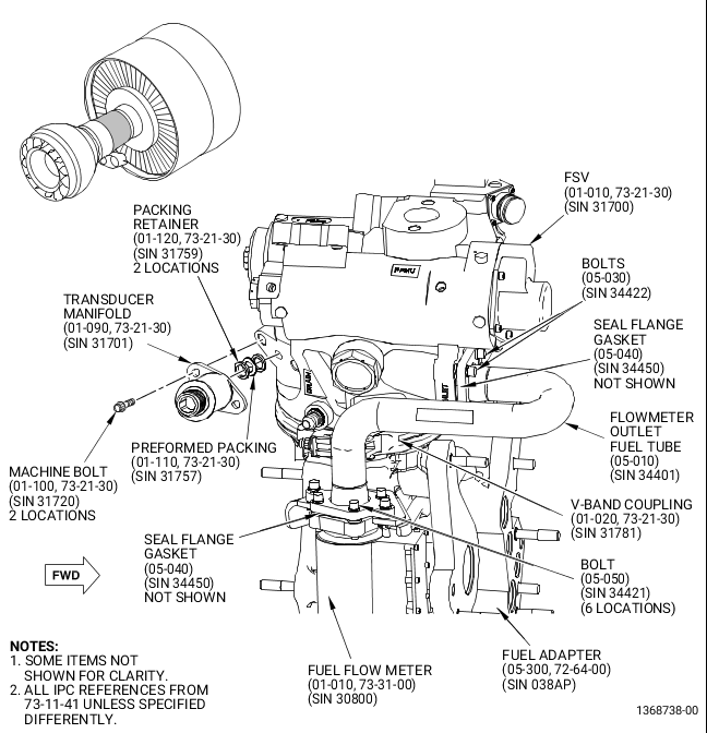
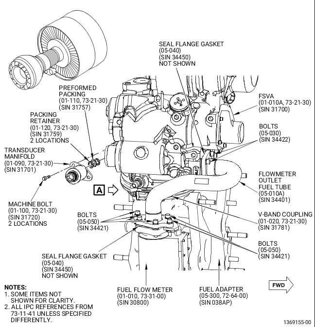
| (33) | Remove flowmeter outlet fuel tube (05-010, 73-11-41) (SIN 34401) and the FSV (01-010, 73-21-30) (SIN 31700) as follows. Refer to Figure 30. |
| CAUTION: |
|
| CAUTION: |
|
| CAUTION: |
|
| (a) | Remove the four machine bolts (05-030, 73-11-41) (SIN 34422) that attach the flowmeter outlet fuel tube (05-010) (SIN 34401) to the FSV (01-010, 73-21-30) (SIN 31700). |
| (b) | Remove the six machine bolts (05-050, 73-11-41) (SIN 34421) that attach the flowmeter outlet fuel tube (05-010) (SIN 34401) to the fuel flow meter (01-010, 73-31-00) (SIN 30800). |
| (c) | Remove the flowmeter outlet fuel tube (05-010, 73-11-41) (SIN 34401) and the two seal flange gaskets (05-040) (SIN 34450) from the engine and install protective covers to the FSV (01-010, 73-21-30) (SIN 31700) and fuel flow meter (01-010, 73-31-00) (SIN 30800). |
| (d) | Discard the flowmeter outlet fuel tube (05-010, 73-11-41) (SIN 34401) and the two seal flange gaskets (05-040) (SIN 34450). Keep the six machine bolts (05-050) (SIN 34421) and the four machine bolts (05-030) (SIN 34422) for installation of the new flowmeter outlet fuel tube. |
| CAUTION: |
|
| (e) | Remove the V-band coupling (01-020, 73-21-30) (SIN 31781) that attach the FSV (01-010) (SIN 31700) to the fuel adapter (05-300, 72-64-00) (SIN 038AP). |
| NOTE: |
|
| NOTE: |
|
| (f) | Remove and discard the FSV (01-010) (SIN 31700) from the fuel adapter (05-300, 72-64-00) (SIN 038AP). |
| (g) | Install protective covers on all the exposed openings. |
| (h) | If necessary, record the serial number from the discarded FSV (01-010, 73-21-30) (SIN 31700) for engine documentation. |
| (i) | Discard all packings and retainers that are attached to the FSV ports. Keep the V-band coupling (01-020, 73-21-30) (SIN 31781) for later installation. The FSV (01-010) (SIN 31700) will be replaced with a new design unit. |
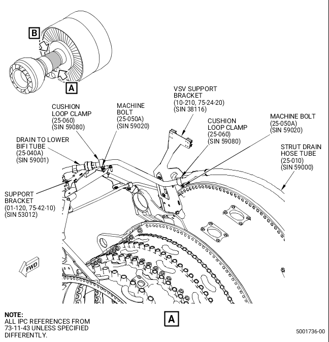
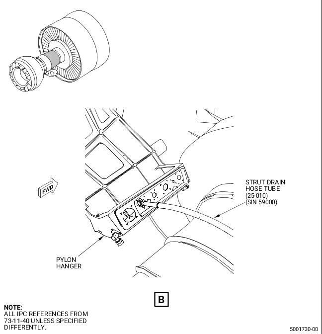
| (34) | Remove the strut drain hose tube (25-010, 73-11-43) (SIN 59000) as follows. Refer to Figure 31. |
| CAUTION: |
|
| (a) | This step is not necessary for in shop performance: Disconnect the strut drain hose tube (25-010, 73-11-43) (SIN 59000) B-nut from the pylon hanger fitting. For the removal of the strut drain hose tube (25-010) (SIN 59000), refer to the GEnx-1B Boeing 787 AMM, DMC-B787-A-G71-00-00-10B-520A-A. |
| (b) | Remove the machine bolt (25-050A, 73-11-43) (SIN 59020) and the cushion loop clamp (25-060) (SIN 59080) that attach the strut drain hose tube (25-010) (SIN 59000) to the support bracket (01-120, 75-42-10) (SIN 53012). |
| (c) | Remove the machine bolt (25-050A, 73-11-43) (SIN 59020) and the cushion loop clamp (25-060) (SIN 59080) that attach the strut drain hose tube (25-010) (SIN 59000) to the VSV support bracket (10-210, 75-24-20) (SIN 38116). |
| (d) | Remove and discard the strut drain hose tube (25-010, 73-11-43) (SIN 59000). |
| (e) | Install protective covers on all exposed openings. |
| (f) | Store the remaining components in bags and label them for re-installation. |
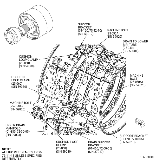
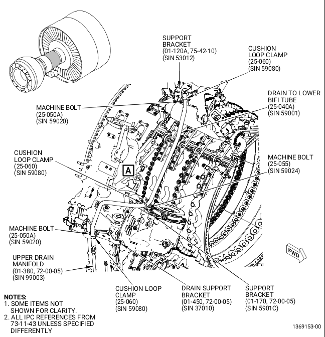
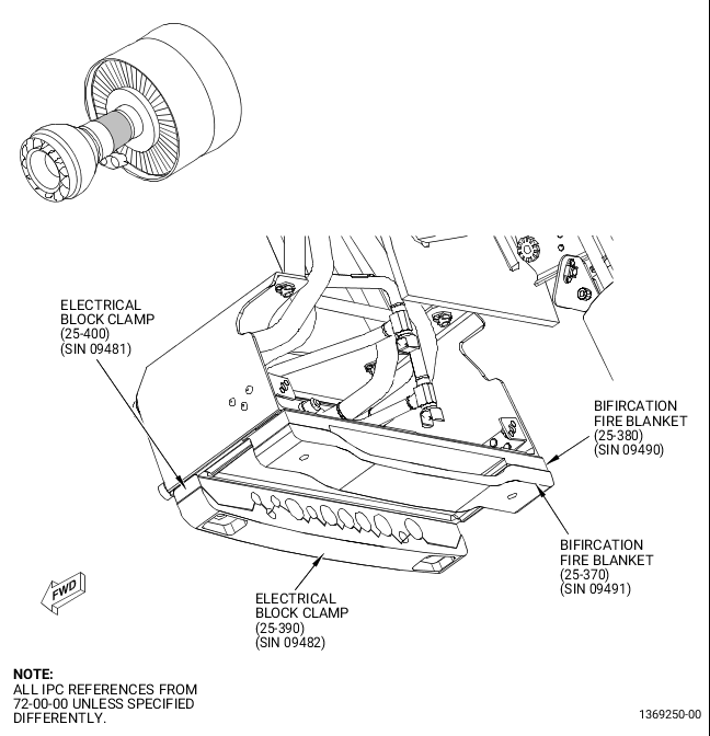
| (35) | Remove the drain to lower bifi tube (25-040, 73-11-43) (SIN 59001) as follows. Refer to Figure 32. |
| CAUTION: |
|
| (a) | Disconnect the drain to lower bifi tube (25-040) (SIN 59001) B-nut connection from the upper drain manifold (01-380, 72-00-05) (SIN 99003). |
| (b) | Remove the machine bolt (25-050A, 73-11-43) (SIN 59020) and the cushion loop clamp (25-060) (SIN 59080) that attach the drain to lower bifi tube (25-040) (SIN 59001) to the support bracket (01-120, 75-42-10) (SIN 53012). |
| (c) | Remove the machine bolt (25-050A, 73-11-43) (SIN 59020) and the cushion loop clamp (25-060) (SIN 59080) that attach the drain to lower bifi tube (25-040) (SIN 59001) to the support bracket (01-170, 72-00-05) (SIN 5901C). |
| (d) | Remove the machine bolt (25-050A, 73-11-43) (SIN 59020) and the cushion loop clamp (25-060) (SIN 59080) that attach the drain to lower bifi tube (25-040) (SIN 59001) to the drain support bracket (01-450, 72-00-05) (SIN 37010). |
| (e) | Remove and discard the drain to lower bifi tube (25-040, 73-11-43) (SIN 59001). |
| (f) | Install protective covers on all exposed openings. |
| (g) | Store the remaining components in bags and label them for re-installation. |
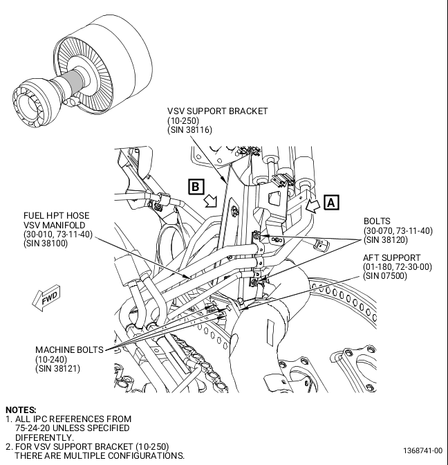
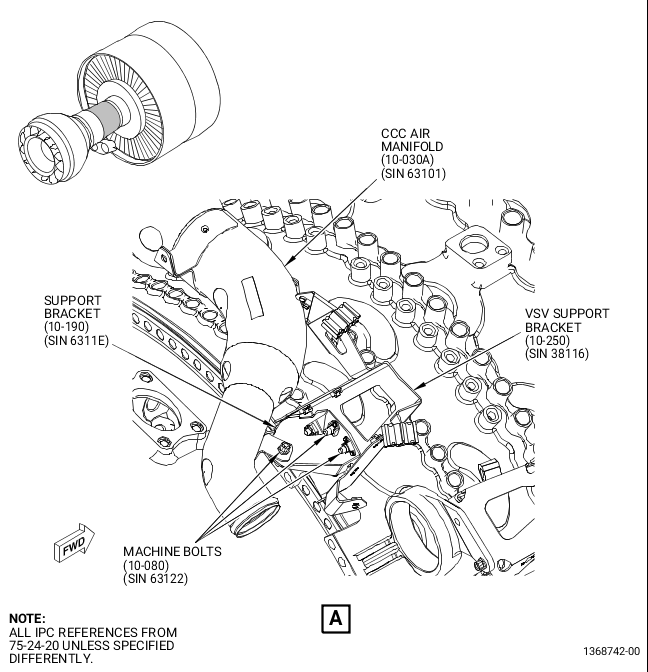
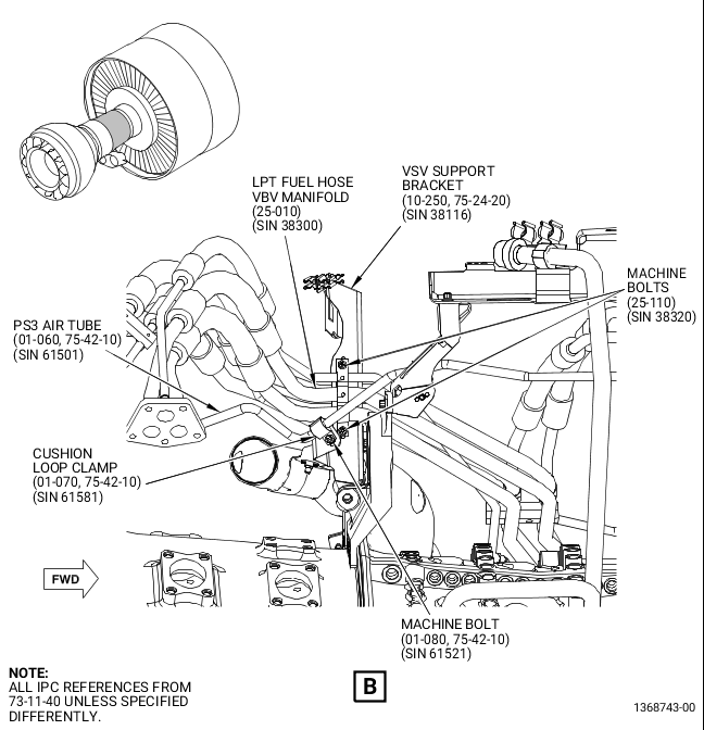
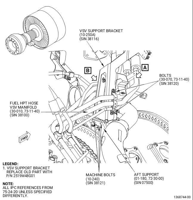
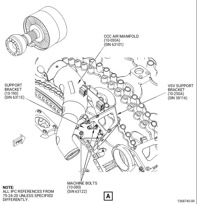
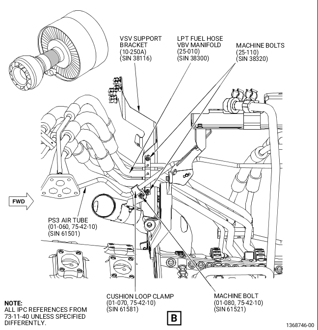
| (36) | Replace the VSV support bracket (10-250, 75-24-20) (SIN 38116) as follows. Refer to Figure 33 and Figure 34. |
| (a) | Remove the machine bolt (01-080, 75-42-10) (SIN 61521) and the cushion loop clamp (01-070) (SIN 61581) that attach the PS3 air tube (01-060) (SIN 61501) to the VSV support bracket (10-250, 75-24-20) (SIN 38116). |
| (b) | Remove the two machine bolts (30-070, 73-11-40) (SIN 38120) that attach the fuel HPT hose VSV manifold (30-010) (SIN 38100) to the VSV support bracket (10-250, 75-24-20) (SIN 38116). |
| (c) | Remove the two machine bolts (25-110, 73-11-40) (SIN 38320) that attach the LPT fuel hose VBV manifold (25-010) (SIN 38300) to the VSV support bracket (10-250, 75-24-20) (SIN 38116). |
| (d) | Remove the three machine bolts (10-080) (SIN 63122) that attach the support bracket (10-190) (SIN 6311E) to the VSV support bracket (10-250) (SIN 38116) and the CCC air manifold (10-030A) (SIN 63101). |
| (e) | Remove the support bracket (10-190) (SIN 6311E) from the engine. |
| (f) | Remove the three machine bolts (10-240) (SIN 38121) that attach the VSV support bracket (10-250) (SIN 38116) to the aft support (01-180, 72-30-00) (SIN 07500). |
| (g) | Remove and discard the VSV support bracket (10-250, 75-24-20) (SIN 38116), two electrical clip inserts (20-020, 73-21-65) (SIN 67172), and two electrical clip inserts (25-050) (SIN 67172) from the engine. |
| (h) | Install the new VSV support bracket (10-250A, 75-24-20) (SIN 38116) and the two machine bolts (30-070, 73-11-40) (SIN 38120) that attach the fuel HPT hose VSV manifold (30-010) (SIN 38100) to the new VSV support bracket (10-250A, 75-24-20) (SIN 38116). Do not torque the machine bolts at this time. |
| (i) | Install the two machine bolts (25-110) (SIN 38320) that attach the LPT fuel hose VBV manifold (25-010) (SIN 38300) to new VSV support bracket (10-250A) (SIN 38116). Do not torque at this time. |
| (j) | Install the three machine bolts (10-240, 75-24-20) (SIN 38121) that attach the new VSV support bracket (10-250A) (SIN 38116) to the aft support (01-180, 72-30-00) (SIN 07500). Do not torque the machine bolts at this time. |
| (k) | Install the support bracket (10-190, 75-24-20) (SIN 6311E) on the new VSV support bracket (10-250A) (SIN 38116) with two machine bolts (10-080) (SIN 63122). |
| (l) | Torque the two machine bolts (10-080) (SIN 63122) and the three machine bolts (10-240) (SIN 38121) to 106-124 lb in. (12.0-14.0 N.m). |
| (m) | Install the machine bolt (10-080) (SIN 63122) that attach the support bracket (10-190) (SIN 6311E) to the CCC air manifold (10-030A) (SIN 63101) and torque to 106-124 lb in. (12.0-14.0 N.m). |
| (n) | Install the machine bolt (01-080, 75-42-10) (SIN 61521) and the cushion loop clamp (01-070) (SIN 61581) that attach the PS3 air tube (01-060) (SIN 61501) to the new VSV support bracket (10-250A) (SIN 38116). Torque the machine bolt (01-080) (SIN 61521) to 32-38 lb in. (3.6-4.3 N.m). |
| (o) | Torque the two machine bolts (25-110, 73-11-40) (SIN 38320) and the two machine bolts (30-070) (SIN 38120) to 32-38 lb in. (3.6-4.3 N.m). |
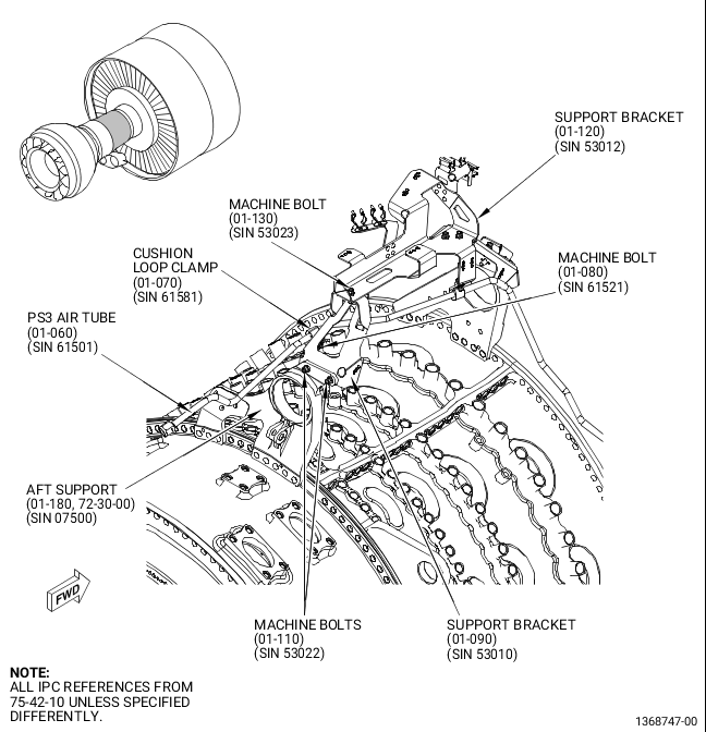
| (37) | Remove the support bracket (01-090, 75-42-10) (SIN 53010) as follows. Refer to Figure 35. |
| (a) | Remove the machine bolt (01-080) (SIN 61521) and the cushion loop clamp (01-070) (SIN 61581) that attach the PS3 air tube (01-060) (SIN 61501) to the support bracket (01-090) (SIN 53010). |
| (b) | Remove the machine bolt (01-130) (SIN 53023) that attaches the support bracket (01-090) (SIN 53010) to the support bracket (01-120) (SIN 53012). |
| (c) | Remove the two machine bolts (01-110) (SIN 53022) that attach the support bracket (01-090) (SIN 53010) to the aft support (01-180, 72-30-00) (SIN 07500). |
| (d) | Remove and discard the support bracket (01-090, 75-42-10) (SIN 53010) from the engine. |
| (e) | Store the remaining components in bags and label them for re-installation. |
| (38) | Remove the support bracket (01-120, 75-42-10) (SIN 53012) as follows. Refer to Figure 36. |
| (a) | Remove the machine bolt (01-080) (SIN 61521) and the cushion loop clamp (01-070) (SIN 61581) that attach the PS3 air tube (01-060) (SIN 61501) to the support bracket (01-120) (SIN 53012). |
| (b) | Remove the two machine bolts (25-060, 73-11-40) (SIN 38322) and the two cushioned loop clamps (25-070) (SIN 38380) that attach the LPT fuel hose VBV manifold (25-010) (SIN 38300) to the support bracket (01-120, 75-42-10) (SIN 53012). |
| (c) | Remove the two machine bolts (05-130, 71-00-00) (SIN 53220) that attach the P-clamp (05-080) (SIN 53080) to the support bracket (01-120, 75-42-10) (SIN 53012) and remove the P-clamp (05-080, 71-00-00) (SIN 53080). |
| (d) | Remove the two machine bolts (01-130) (SIN 53023) that attach the support bracket (01-120) (SIN 53012) to the support bracket (01-100) (SIN 53011). |
| (e) | Remove and discard the support bracket (01-120) (SIN 53012). |
| (f) | Store the remaining components in bags and label them for re-installation. |
| C. | Assembly of the FSVA and External Hardware |
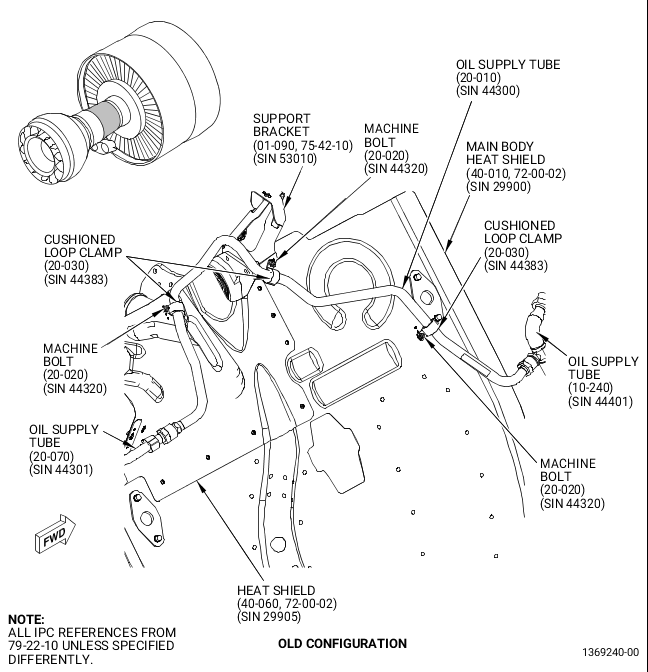
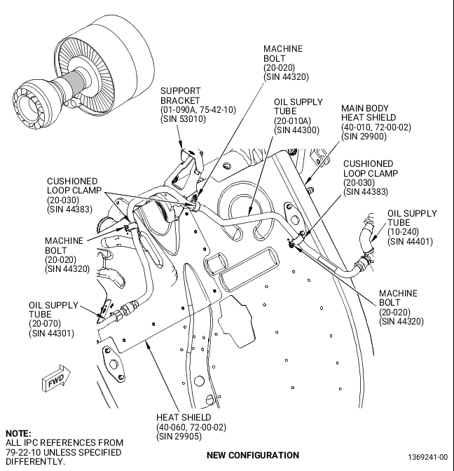
| (1) | Replace the oil supply tube (20-010, 79-22-10) (SIN 44300) with new oil supply tube (20-010A, 79-22-10) (SIN 44300) as follows. Refer to Figure 37. |
| (a) | Remove the machine bolt (20-020) (SIN 44320) and the cushioned loop clamp (20-030) (SIN 44383) that attach the oil supply tube (20-010) (SIN 44300) to the heat shield (40-060, 72-00-02) (SIN 29905). |
| (b) | Remove the machine bolt (20-020, 79-22-10) (SIN 44320) and the cushioned loop clamp (20-030) (SIN 44383) that attach the oil tube (20-010) (SIN 44300) to the support bracket (01-090, 75-42-10) (SIN 53010). |
| (c) | Remove the machine bolt (20-020, 79-22-10) (SIN 44320) and the cushioned loop clamp (20-030) (SIN 44383) that attach the oil supply tube (20-010) (SIN 44300) to the main body heat shield (40-010, 72-00-02) (SIN 29900). |
| CAUTION: |
|
| NOTE: |
|
| (d) | Disconnect the B-nut that attaches the oil supply tube (20-010, 79-22-10) (SIN 44300) to the oil supply tube (20-070) (SIN 44301). |
| (e) | Disconnect the B-nut that attaches the oil supply tube (20-010) (SIN 44300) to the oil supply tube (10-240) (SIN 44401). |
| (f) | Remove and discard the oil supply tube (20-010) (SIN 44300) from the engine. |
| (g) | Install the new oil supply tube (20-010A, 79-22-10) (SIN 44300) on the oil supply tube (20-070) (SIN 44301) and the oil supply tube (10-240) (SIN 44401) and attach the B-nuts. Hand-tighten the B-nuts. |
| (h) | Attach the new oil supply tube (20-010A) (SIN 44300) to heat shield (40-060, 72-00-02) (SIN 29905) and main body heat shield (40-010, 72-00-02) (SIN 29900) with two machine bolts (20-020, 79-22-10) (SIN 44320) and two cushioned loop clamps (20-030) (SIN 44383). Hand-tighten the machine bolts (20-020) (SIN 44320). |
| NOTE: |
|
| CAUTION: |
|
| (i) | Triple-torque the B-nut that attaches the oil supply tube (20-010A, 79-22-10) (SIN 44300) to oil supply tube (20-070) (SIN 44301) to 662-778 lb in. (74.8-87.9 N.m). Refer to the SPM, 70-51-00, TIGHTENING PRACTICES AND TORQUE VALUES, TASK 70-51-00-400-004. |
| (j) | Triple-torque the B-nut that attaches the oil supply tube (20-010A) (SIN 44300) to oil supply tube (10-240) (SIN 44401) to 662-778 lb in. (74.8-87.9 N.m). Refer to the SPM, 70-51-00, TIGHTENING PRACTICES AND TORQUE VALUES, TASK 70-51-00-400-004. |
| (k) | Torque the two machine bolts (20-020) (SIN 44320), installed in paragraph C., step (1) (h), that attach the new oil supply tube (20-010A) (SIN 44300) to 32-38 lb in. (3.6-4.3 N.m). |
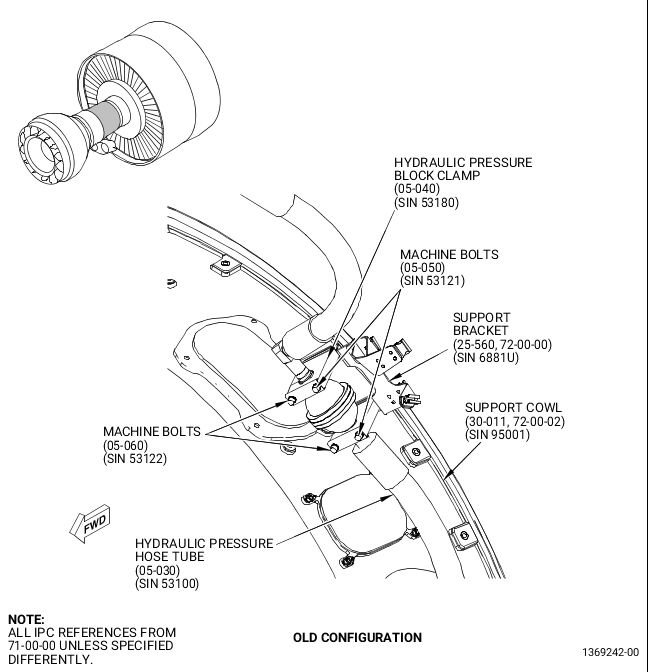
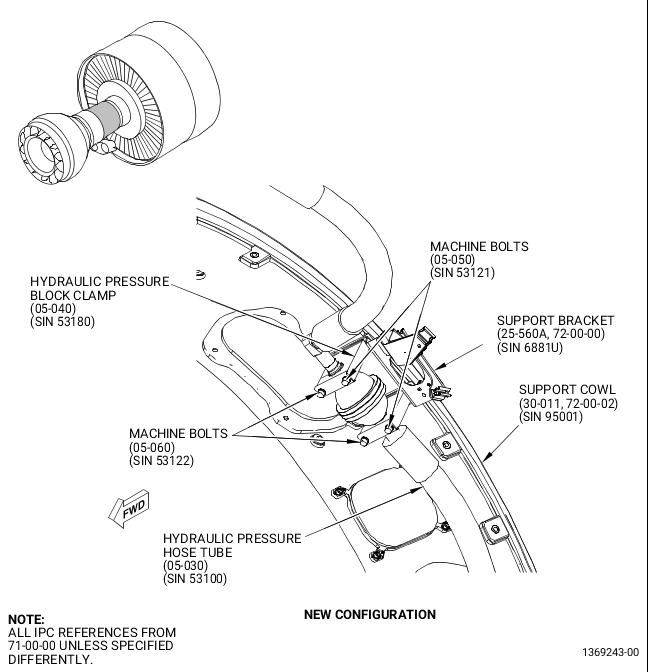
| (2) | Replace the support bracket (25-560, 72-00-00) (SIN 6881U) with new support bracket (25-560A, 72-00-00) (SIN 6881U) as follows. Refer to Figure 38. |
| WARNING: |
|
| (a) | Apply C03-001 primer or an alternative primer to the surface of the new support bracket (25-560A) (SIN 6881U) that will contact the cowl support. |
| (b) | Remove the two machine bolts (05-060, 71-00-00) (SIN 53122) and two machine bolts (05-050) (SIN 53121) that attach the hydraulic pressure hose tube (05-030) (SIN 53100) to the fan cowl support (30-011, 72-00-02) (SIN 95001). Remove the hydraulic pressure block clamps (05-040, 71-00-00) (SIN 53180). |
| (c) | Remove and discard the support bracket (25-560, 72-00-00) (SIN 6881U) and install the new support bracket (25-560A) (SIN 6881U) on the fan cowl support (30-011, 72-00-02) (SIN 95001) with the nut plates boltholes aligned with two machine bolts (05-060, 71-00-00) (SIN 53122) and two machine bolts (05-050) (SIN 53121). |
| NOTE: |
|
| (d) | Install the hydraulic pressure block clamps (05-040) (SIN 53180) on the hydraulic pressure hose tube (05-030) (SIN 53100) and the fan cowl support (30-011, 72-00-02) (SIN 95001) with boltholes aligned. Insert two machine bolts (05-060, 71-00-00) (SIN 53122) thru the forward set of holes in the hydraulic pressure block clamps (05-040) (SIN 53180) and the new support bracket (25-560A, 72-00-00) (SIN 6881U) and hand-tighten them into the fan cowl support (30-011, 72-00-02) (SIN 95001) nut plates. |
| (e) | Insert the aft machine bolts (05-050, 71-00-00) (SIN 53121) thru the hydraulic pressure block clamps (05-040) (SIN 53180) and the new support bracket (25-560A, 72-00-00) (SIN 6881U), and turn and hand-tighten them into the fan cowl support (30-011, 72-00-02) (SIN 95001) nut plates. |
| (f) | Torque two machine bolts (05-060, 71-00-00) (SIN 53122) and two machine bolts (05-050) (SIN 53121) to 106-124 lb in. (12.0-14.0 N.m). |
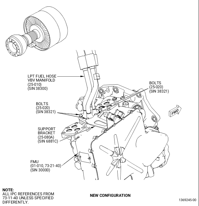
| (3) | Replace the support bracket (25-080,73-11-40) (SIN 6881C) with new support bracket (25-080A, 73-11-40) (SIN 6881C) as follows. Refer to Figure 39. |
| (a) | Remove the two machine bolts (25-020) (SIN 38321) that attach the support bracket (25-080) (SIN 6881C) from the top of LPT fuel hose VBV manifold (25-010) (SIN 38300) flange and remove the support bracket (25-080) (SIN 6881C) from the engine. |
| (b) | Install the new support bracket (25-080A, 73-11-40) (SIN 6881C) on top of the LPT fuel hose VBV manifold (25-010) (SIN 38300) flange with its boltholes aligned and with the two open holes in the manifold flange. |
| (c) | Insert the two machine bolts (25-020) (SIN 38321) thru the new support bracket (25-080A) (SIN 6881C) and the flange of LPT fuel hose VBV manifold (25-010) (SIN 38300) and put them into the FMU (01-010, 73-21-40) (SIN 30000). Torque the two machine bolts (25-020, 73-11-40) (SIN 38321) to 106-124 lb in. (12.0-14.0 N.m). |
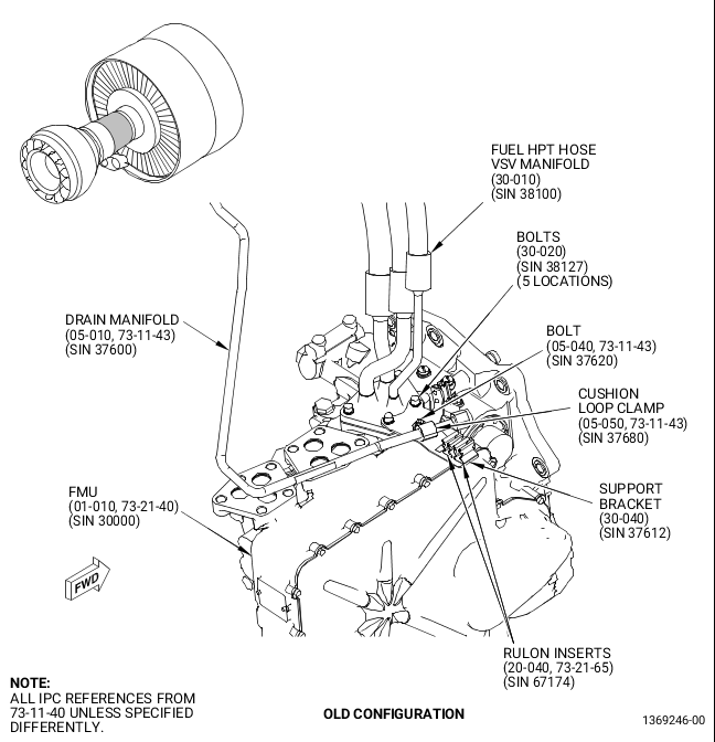
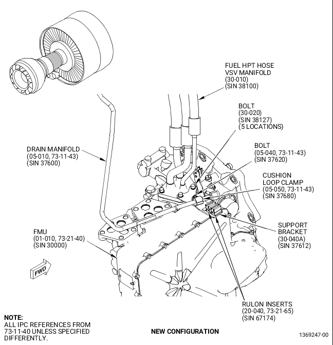
| (4) | Replace support bracket (30-040, 73-11-40) (SIN 37612) with new support bracket (30-040A, 73-11-40) (SIN 37612) as follows. Refer to Figure 40. |
| (a) | Remove the machine bolt (05-040, 73-11-43) (SIN 37620) and the cushioned loop clamp (05-050) (SIN 37620) that attach the drain manifold (05-010) (SIN 37600) to the support bracket (30-040, 73-11-40) (SIN 37612). |
| (b) | Remove the two machine bolts (30-020, 73-11-40) (SIN 38127) that attach the support bracket (30-040) (SIN 37612) to the top of the fuel HPT hose VSV manifold (30-010) (SIN 38100) mounting flange and remove the support bracket (30-040) (SIN 37612) from the engine. |
| NOTE: |
|
| (c) | Put the new support bracket (30-040A, 73-11-40) (SIN 37612) on top of the fuel HPT hose VSV manifold (30-010) (SIN 38100) mounting flange with its boltholes aligned with the open boltholes in the fuel HPT hose VSV manifold (30-010) (SIN 38100) mounting flange. |
| (d) | Install the two machine bolts (30-020) (SIN 38127) thru the new support bracket (30-040A) (SIN 37612) and fuel HPT hose VSV manifold (30-010) (SIN 38100) mounting flange and attach them into the FMU (01-010, 73-21-40) (SIN 30000). |
| (e) | Torque the two machine bolts (30-020, 73-11-40) (SIN 38127) to 106-124 lb in. (12.0-14.0 N.m). |
| (f) | Install the drain manifold (05-010, 73-11-43) (SIN 37600) to the new support bracket (30-040A, 73-11-40) (SIN 37612) with one machine bolt (05-040, 73-11-43) (SIN 37620) and one cushioned loop clamp (05-050) (SIN 37680). |
| (g) | Torque the machine bolt (05-040) (SIN 37620) to 32-38 lb in. (3.6-4.3 N.m). |
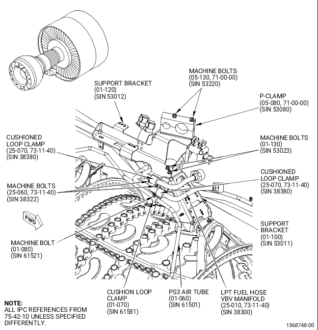
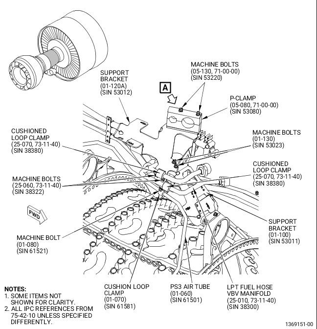
| (5) | Install the new support bracket (01-120A, 75-42-10) (SIN 53012) as follows. Refer to Figure 41. |
| (a) | Install the new support bracket (01-120A) (SIN 53012) to the support bracket (01-100) (SIN 53011) with two machine bolts (01-130) (SIN 53023). |
| (b) | Torque the two machine bolts (01-130) (SIN 53023) that attach the support bracket (01-120A) (SIN 53012) to the support bracket (01-100) (SIN 53011) to 106-124 lb in. (12.0-14.0 N.m). |
| (c) | Install the P-clamp (05-080, 71-00-00) (SIN 53080) on the tube hose (05-070) (SIN 53000) and the tube hose (05-110) (SIN 53200), and install the two machine bolts (05-130) (SIN 53220) thru P-clamp (05-080) (SIN 53080) and into the nut plates on the new support bracket (01-120A, 75-42-10) (SIN 53012). |
| (d) | Torque the two machine bolts (05-130, 71-00-00) (SIN 53220) to 106-124 lb in. (12.0-14.0 N.m). |
| (e) | Install the LPT fuel hose VBV manifold (25-010, 73-11-40) (SIN 38300) to the support bracket (01-120A, 75-42-10) (SIN 53012) with two machine bolts (25-060, 73-11-40) (SIN 38322) and two cushioned loop clamps (25-070) (SIN 38380). |
| (f) | Torque the two machine bolts (25-060) (SIN 38322) to 32-38 lb in. (3.6-4.3 N.m). |
| (g) | Install the PS3 air tube (01-060, 75-42-10) (SIN 61501) to the support bracket (01-120A) (SIN 53012) with one machine bolt (01-080) (SIN 61521) and one cushioned loop clamp (01-070) (SIN 61581). Torque the machine bolt (01-080) (SIN 61521) to 32-38 lb in. (3.6-4.3 N.m). |
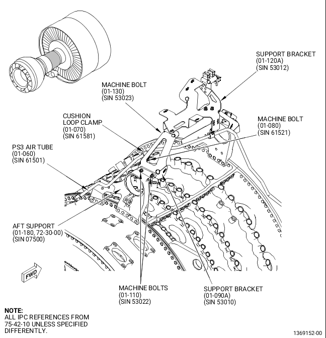
| (6) | Install the new support bracket (01-090A) (SIN 53010) as follows. Refer to Figure 42. |
| (a) | Put the new support bracket (01-090A) (SIN 53010) on the new support bracket (01-120A) (SIN 53012) and the aft flange on the AFT support (01-180, 72-30-00) (SIN 07500) with boltholes aligned. |
| (b) | Install one machine bolt (01-130, 75-42-10) (SIN 53023) thru support bracket (01-120A) (SIN 53012) and into the nut plate on the support bracket (01-090A) (SIN 53010). Hand-tighten the machine bolt (01-130) (SIN 53023). |
| (c) | Install the support bracket (01-090A) (SIN 53010) to the AFT support (01-180, 72-30-00) (SIN 07500) with two machine bolts (01-110, 75-42-10) (SIN 53022). Hand-tighten the machine bolts (01-110) (SIN 53022). |
| (d) | Torque the machine bolt (01-130) (SIN 53023) that attaches the support bracket (01-120A) (SIN 53012) to support bracket (01-090A) (SIN 53010) and the two machine bolts (01-110) (SIN 53022) to 106-124 lb in. (12.0-14.0 N.m). |
| (e) | Install the PS3 air tube (01-060) (SIN 61501) to the support bracket (01-090A) (SIN 53010) with one machine bolt (01-080) (SIN 61521) and one cushioned loop clamp (01-070) (SIN 61581). |
| (f) | Torque the machine bolt (01-080) (SIN 61521) to 32-38 lb in. (3.6-4.3 N.m). |
| (g) | Install the oil supply tube (20-010A, 79-22-10) (SIN 44300) to new support bracket (01-090A, 75-42-10) (SIN 53010) with one machine bolt (20-020, 79-22-10) (SIN 44320) and one cushioned loop clamp (20-030) (SIN 44383). Refer to Figure 37. |
| (h) | Torque the machine bolt (20-020) (SIN 44320) to 32-38 lb in. (3.6-4.3 N.m). |
| (7) | Install the new drain to lower bifi tube (25-040A, 73-11-43) (SIN 59001) as follows. Refer to Figure 43. |
| CAUTION: |
|
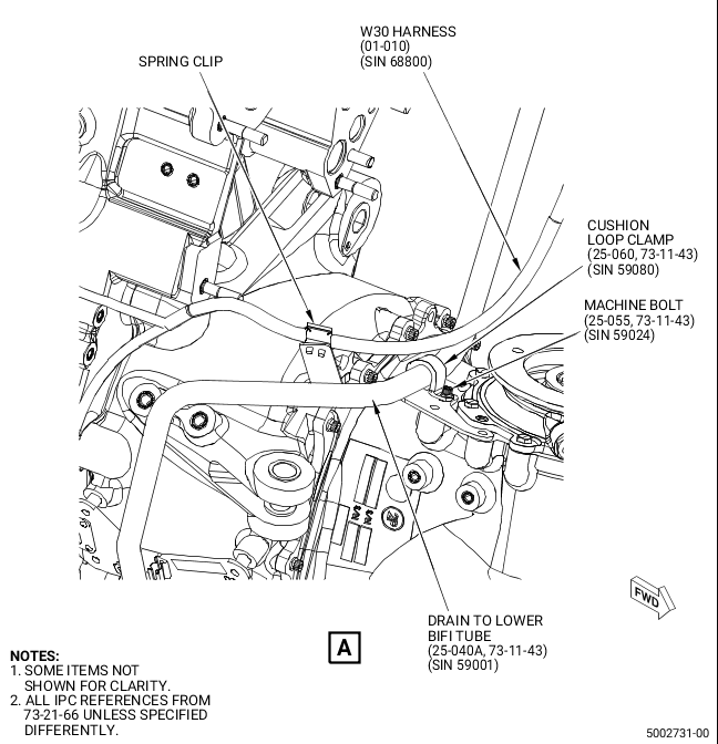
| (a) | To make the installation easier for drain to lower bifi tube (25-040A, 73-11-43) (SIN 59001), remove the W05 harness connector P056 at the fuel flow meter and attach it out of the way. |
| (b) | Install the new drain to lower bifi tube (25-040A) (SIN 59001) on the upper drain manifold (01-380, 72-00-05) (SIN 99003) and hand-tighten the B-nut. |
| (c) | Attach the drain to lower bifi tube (25-040A, 73-11-43) (SIN 59001) to support bracket (01-120A, 75-42-10) (SIN 53012) with one machine bolt (25-050A, 73-11-43) (SIN 59020) and one cushioned loop clamp (25-060) (SIN 59080). Hand-tighten the machine bolt (25-050A) (SIN 59020). |
| (d) | Attach the drain to lower bifi tube (25-040A) (SIN 59001) to drain support bracket (01-170, 72-00-05) (SIN 5901C) with one machine bolt (25-055, 73-11-43) (SIN 59024) and one cushioned loop clamp (25-060) (SIN 59080). Hand-tighten the machine bolt (25-055) (SIN 59024). |
| (e) | Attach the drain to lower bifi tube (25-040A) (SIN 59001) to drain support bracket (01-450, 72-00-05) (SIN 37010) with one machine bolt (25-050A, 73-11-43) (SIN 59020) and one cushioned loop clamp (25-060) (SIN 59080). Hand-tighten the machine bolt (25-050A) (SIN 59020). |
| CAUTION: |
|
| (f) | Torque the B-nut of the new drain to lower bifi tube (25-040A, 73-11-43) (SIN 59001) to the upper drain manifold (01-380, 72-00-05) (SIN 99003) to 460-540 lb in. (52.0-61.0 N.m). |
| (g) | Torque the two machine bolts (25-050A, 73-11-43) (SIN 59020) and one machine bolt (25-055) (SIN 59024) to 32-38 lb in. (3.6-4.3 N.m). |
| CAUTION: |
|
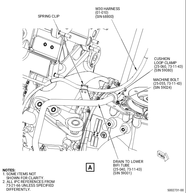
| (h) | Install W30 harness (01-010, 73-21-66) (SIN 68800) to spring clip in bracket attached to new drain to lower bifi tube (25-040A, 73-11-43) (SIN 59001) again and reconnect the W05 harness connector P056 to the fuel flow meter with soft jawed pliers. |
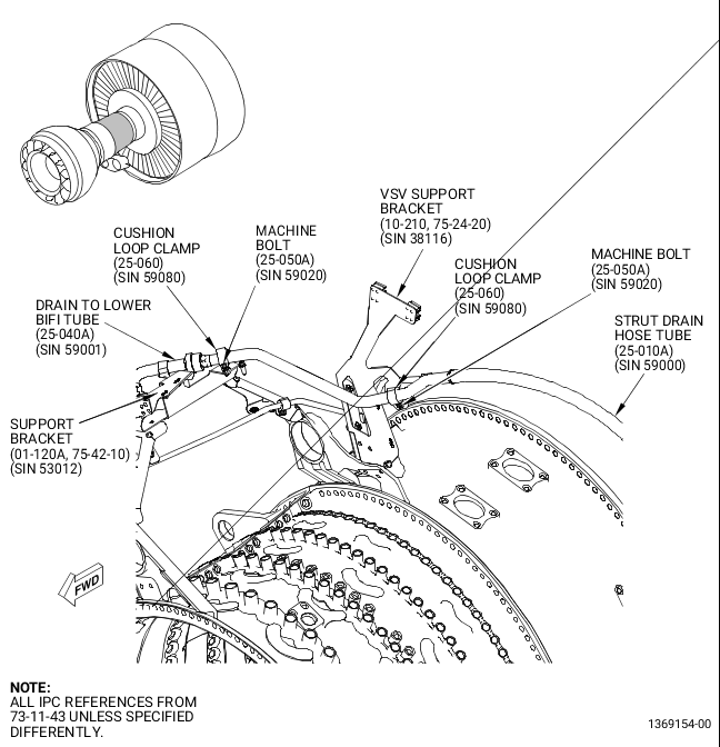
| (8) | Install the new strut drain hose tube (25-010A, 73-11-43) (SIN 59000) as follows. Refer to Figure 1 and Figure 44. |
| (a) | This step is not necessary for in shop performance: Install the new strut drain hose tube (25-010A, 73-11-43) (SIN 59000) with the B-nut finger tight on the fitting on the pylon hanger. |
| (b) | Install the new strut drain hose tube (25-010A) (SIN 59000) to the new drain to lower bifi tube (25-040A) (SIN 59001). Hand-tighten the B-nut. |
| (c) | Attach the new strut drain hose tube (25-010A) (SIN 59000) to the new VSV support bracket (10-210A, 75-24-20) (SIN 38116) with one machine bolt (25-050A, 73-11-43) (SIN 59020) and one cushioned loop clamp (25-060) (SIN 59080). Hand-tighten the machine bolt (25-050A) (SIN 59020). |
| (d) | Attach the new strut drain hose tube (25-010A) (SIN 59000) to the support bracket (01-120A, 75-42-10) (SIN 53012) with one machine bolt (25-050A, 73-11-43) (SIN 59020) and one cushioned loop clamp (25-060) (SIN 59080). Hand-tighten the machine bolt (25-050A) (SIN 59020). |
| CAUTION: |
|
| (e) | Torque the B-nut of the new strut drain hose tube (25-010A) (SIN 59000) and new drain to lower bifi tube (25-040A) (SIN 59001) to 938-1102 lb in. (106.0-124.5 N.m). |
| (f) | This step is not necessary for in shop performance: Install and torque the B-nut fitting that attach the new strut drain hose tube (25-010A) (SIN 59000) to the pylon hanger. Refer to the GEnx-1B Boeing 787 AMM, DMC-B787-A-G71-00-00-10B-720A-A, step 1.C.(26)(d) and Figure 1. |
| (g) | Torque the machine bolt (25-050A, 73-11-43) (SIN 59020) installed at paragraph C., step (8)(c) and (8)(d) to 32-38 lb in. (3.6-4.3 N.m). |
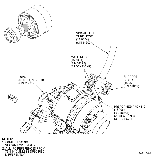
| (9) | Prepare the new FSVA (01-010A, 73-21-30) (SIN 31700) and install as follows. Refer to Figure 45 and Figure 46. |
| (a) | Before the FSVA (01-010A) (SIN 31700) is installed, if necessary record the serial number from the new FSVA (01-010A, 73-21-30) (SIN 31700) for engine documentation. |
| (b) | Install the new cap (01-130) (SIN 31760) on the new FSVA PD fitting attachment. Triple-torque to 262-308 lb in. (29.6-34.8 N.m) and install the C10-143 safety cable to the adjacent blue cap. Refer to Figure 46. |
| NOTE: |
|
| (c) | On a work bench, install the new packings and retainers as follows: |
| WARNING: |
|
| 1 | Apply C02-019 engine oil or C02-023 engine oil on all preformed packings and retainers before installation. |
| 2 | Install four preformed packings and eight packing retainers on the FSVA (01-010A) (SIN 31700) at the fuel inlet ports. Refer to Figure 45 for significant item number (SIN) installation locations. |
| (d) | Install FSVA (01-010A) (SIN 31700) on engine as follows: |
| 1 | Install the new FSVA (01-010A) (SIN 31700) on the lift fixture as follows: |
| WARNING: |
|
| a | Use an overhead hoist with a minimum lifting capacity of 45 kg (100 lbs) and lift the new FSVA (01-010A) (SIN 31700) up to the mounting interface on the 11C4641 adapter. |
| b | Align the three threaded bosses of the new FSVA (01-010A) (SIN 31700) with the mount holes on the adapter interface and attach them with three 0.250-28 cap screws. |
| c | Remove the overhead hoist from the new FSVA (01-010A) (SIN 31700). |
| CAUTION: |
|
| NOTE: |
|
| d | Move the 9446M93 jack stand and adapter assembly with the new FSVA (01-010A) (SIN 31700) attached at the installation location. |
| WARNING: |
|
| CAUTION: |
|
| e | Lift the 9446M93 jack stand to the applicable height to where the new FSVA (01-010A) (SIN 31700) will be installed on the gearbox fuel adapter (05-300, 72-64-00) (SIN 038AP). |
| 2 | Align the new FSVA (01-010A, 73-21-30) (SIN 31700) with the two pins on the gearbox fuel adapter (05-300, 72-64-00) (SIN 038AP) FSVA mounting pad and install the FSVA (01-010A, 73-21-30) (SIN 31700). Keep the flange of the FSVA (01-010A) (SIN 31700) parallel to the mating surface of the gearbox fuel adapter (05-300, 72-64-00) (SIN 038AP) during assembly. Keep them parallel until the mating flanges are fully seated. |
| a | After the FSVA (01-010A, 73-21-30) (SIN 31700) is mounted on the AGB fuel adapter (05-300, 72-64-00) (SIN 038AP) FSVA mounting pad, remove the three screws from the mounting interface on the adapter and move it and the jack stand away from the engine. |
| 3 | Install the V-band coupling (01-020, 73-21-30) (SIN 31781) that attach the new FSVA (01-010A) (SIN 31700) to the gearbox fuel adapter (05-300, 72-64-00) (SIN 038AP) FSVA mounting pad. Torque to 110-130 lb in. (12.4-14.7 N.m). Use a non-marring hammer to tap around the circumference of the clamp. Torque again and repeat the process until there is no rotation of the V-band coupling (01-020, 73-21-30) (SIN 31781) nut. |
| CAUTION: |
|
| (e) | Connect the drain tube (05-020, 73-11-43) (SIN 37601) B-nut on the fitting on the new FSVA (01-010A, 73-21-30) (SIN 31700) and torque to 262-308 lb in. (29.6-34.8 N.m). Refer to Figure 46. |
| (f) | Install fuel manifold transducer (01-090, 73-21-30) (SIN 31701) as follows. Refer to Figure 45. |
| 1 | Remove two machine bolts (01-100) (SIN 31720) and remove manifold transducer (01-090) (SIN 31701) from the discarded FSV (01-010) (SIN 31700). |
| 2 | Remove and discard packing (01-110) (SIN 31757) and two packing retainers (01-120) (SIN 31759) from the manifold transducer (01-090, 73-21-30) (SIN 31701). |
| WARNING: |
|
| 3 | Lubricate one new packing (01-110) (SIN 31757) with C02-019 engine oil or C02-023 engine oil. |
| 4 | Install one new packing (01-110) (SIN 31757) and two new packing retainers (01-120) (SIN 31759) on the fuel manifold transducer (01-090) (SIN 31701). |
| 5 | Remove protective cover and install the fuel manifold transducer (01-090) (SIN 31701) on the new FSVA (01-010A) (SIN 31700) mounting flange. |
| 6 | Install the two machine bolts (01-100) (SIN 31720) that attach the fuel manifold transducer (01-090) (SIN 31701) to the new FSVA (01-010A) (SIN 31700) and torque to 106-124 lb in. (12.0-14.0 N.m). |
| CAUTION: |
|
| (g) | Remove protective cover and install W12 harness (50-010, 73-21-65) (SIN 6700A) on the fuel manifold transducer (01-090, 73-21-30) (SIN 31701) with a soft-jawed pliers. Refer to Figure 46. |
| (10) | Install the new flowmeter outlet fuel tube (05-010A, 73-11-41) (SIN 34401) as follows. Refer to Figure 45. |
| WARNING: |
|
| (a) | Lubricate the threads of the four machine bolts (05-030, 73-11-41) (SIN 34422) and six machine bolts (05-050) (SIN 34421) with C02-058 lubricant. |
| (b) | Install a new seal flange gasket (05-040) (SIN 34450) on the FSVA (01-010A, 73-21-30) (SIN 31700) mounting flange and install the new flowmeter outlet fuel tube (05-010A, 73-11-41) (SIN 34401) on the FSVA (01-010A, 73-21-30) (SIN 31700) with the tube and gasket boltholes aligned with the FSVA threaded inserts. |
| (c) | Install the flowmeter outlet fuel tube (05-010A, 73-11-41) (SIN 34401) to the FSVA (01-010A, 73-21-30) (SIN 31700) with the four machine bolts (05-030, 73-11-41) (SIN 34422). Hand-tighten the four machine bolts (05-030) (SIN 34422). |
| (d) | Install a new seal flange gasket (05-040) (SIN 34450) between the fuel flow meter (01-010, 73-31-00) (SIN 30800) mounting flange and the flowmeter outlet fuel tube (05-010A, 73-11-41) (SIN 34401) with the boltholes aligned. |
| (e) | Attach the flowmeter outlet fuel tube (05-010A) (SIN 34401) to the fuel flow meter (01-010, 73-31-00) (SIN 30800) with six machine bolts (05-050, 73-11-41) (SIN 34421). |
| (f) | Torque the six machine bolts (05-050) (SIN 34421) to 106-124 lb in. (12.0-14.0 N.m). |
| (g) | Torque the four machine bolts (05-030) (SIN 34422) that attach the flowmeter outlet fuel tube (05-010A) (SIN 34401) to the FSVA (01-010A, 73-21-30) (SIN 31700) to 106-124 lb in. (12.0-14.0 N.m). |
| (11) | Install the new fuel supply tube hose (05-010A, 73-11-40) (SIN 34100) and new support bracket (05-090A) (SIN 6881A) as follows. Refer to Figure 47. |
| WARNING: |
|
| (a) | Lubricate the two new preformed packings (10-070) (SIN 34150) with C02-019 engine oil or C02-023 engine oil, remove the protective covers and install them on each open end of the new fuel supply tube hose (05-010A, 73-11-40) (SIN 34100). |
| (b) | Put the new fuel supply tube hose (05-010A) (SIN 34100) on the engine and attach the B-nut fittings of fuel manifolds (10-010) (SIN 34101) and (10-020) (SIN 34102) to the fuel supply tube hose (05-010A) (SIN 34100). Hand-tighten the B-nuts. |
| (c) | Attach the new fuel supply tube hose (05-010A) (SIN 34100) to support bracket (33-320, 72-00-02) (SIN 3411E) with one machine bolt (05-060, 73-11-40) (SIN 34121) and one cushioned loop clamp (05-070) (SIN 34182). Hand-tighten the machine bolt (05-060) (SIN 34121). |
| (d) | Attach the new fuel supply tube hose (05-010A) (SIN 34100) to support bracket (33-110, 72-00-02) (SIN 34111) with one machine bolt (05-060, 73-11-40) (SIN 34121) and one cushioned loop clamp (05-070) (SIN 34182). Hand-tighten the machine bolt (05-060) (SIN 34121). |
| (e) | Attach the new fuel supply tube hose (05-010A) (SIN 34100) to support bracket (33-150, 72-00-02) (SIN 34117) with one bolt (05-060, 73-11-40) (SIN 34121) and one cushioned loop clamp (05-070) (SIN 34182). Hand-tighten the bolt (05-060) (SIN 34121). |
| (f) | Attach the new fuel supply tube hose (05-010A) (SIN 34100) to support bracket (33-290, 72-00-02) (SIN 6101K) with one machine bolt (05-020, 73-11-40) (SIN 34122) and one cushioned loop clamp (05-070) (SIN 34182). Hand-tighten the machine bolt (05-020) (SIN 34122). |
| CAUTION: |
|
| (g) | Triple-torque the B-nut of the fuel supply tube hose (05-010A) (SIN 34100) and fuel manifold (10-020) (SIN 34102) to 1325-1555 lb in. (149.7-175.7 N.m) and install the C10-143 safety cable or C10-071 safety wire. Refer to the SPM, 70-51-00, TIGHTENING PRACTICES AND TORQUE VALUES, TASK 70-51-00-400-004. |
| (h) | Triple-torque the B-nut of the fuel supply tube hose (05-010A) (SIN 34100) and fuel manifold (10-010) (SIN 34101) to 1325-1555 lb in. (149.7-175.7 N.m) and install the C10-143 safety cable or C10-071 safety wire. Refer to the SPM, 70-51-00, TIGHTENING PRACTICES AND TORQUE VALUES, TASK 70-51-00-400-004. |
| WARNING: |
|
| (i) | Lubricate two preformed packings (05-030A) (SIN 34152) with C02-019 engine oil or C02-023 engine oil. |
| (j) | Install two new preformed packings (05-030A) (SIN 34152) on the flange end of new fuel supply tube hose (05-010A) (SIN 34100). |
| (k) | Insert the flange end of new fuel supply tube hose (05-010A) (SIN 34100) into the FSVA (01-010A, 73-21-30) (SIN 31700). |
| (l) | Put the new bracket (05-090A, 73-11-40) (SIN 6881A) on the top of the fuel supply tube hose (05-010A) (SIN 34100) mounting flange. |
| 1 | Do not transfer two rulon electrical clip insert (20-020, 73-21-65) (SIN 67172) from the existing bracket (05-090, 73-11-40) (SIN 6881A) to the new bracket (05-090A, 73-11-40) (SIN 6881A). |
| (m) | Install the fuel supply tube hose (05-010A) (SIN 34100) to the FSVA (01-010A, 73-21-30) (SIN 31700) with two machine bolts (05-040A, 73-11-40) (SIN 34123). |
| (n) | Torque the two machine bolts (05-040A) (SIN 34123) to 106-124 lb in. (12.0-14.0 N.m). |
| (o) | Torque the machine bolt (05-020) (SIN 34122) and the four machine bolts (05-060) (SIN 34121) to 32-38 lb in. (3.6-4.3 N.m). |
| (12) | Install the new signal fuel tube hose (15-020A) (SIN 34200), support bracket (01-190, 73-11-30) (SIN 6221B), and support bracket (01-210) (SIN 62116) on the left side of the engine as follows. Refer to Figure 48. |
| WARNING: |
|
| (a) | Lubricate the two new preformed packings (15-210, 73-11-40) (SIN 34250) with C02-019 engine oil or C02-023 engine oil, remove the protective covers and install them on each open end of the new signal fuel tube hose (15-020A, 73-11-40) (SIN 34200). |
| (b) | Put the new signal fuel tube hose (15-020A, 73-11-40) (SIN 34200) on the engine and engage the B-nut fittings of the signal fuel tube hose to the manifold (15-050) (SIN 34201) and manifold (15-060) (SIN 34202) to the new signal fuel tube hose (15-020A, 73-11-40) (SIN 34200). Hand-tighten the B-nuts. |
| (c) | Install the support bracket (01-190, 73-11-30) (SIN 6221B) on the support bracket (10-100, 75-24-10) (SIN 6221C) and fuel nozzle (05-200, 73-11-30) (SIN 12501) at fuel nozzle position 18 ALF with the boltholes aligned as follows: |
| 1 | Install the support bracket (01-190) (SIN 6221B) to support bracket (10-100, 75-24-10) (SIN 6221C) with two machine bolts (10-090) (SIN 62220). Hand-tighten the two machine bolts (10-090) (SIN 62220). |
| WARNING: |
|
| 2 | Lubricate the threads of the two machine bolts (05-010, 73-11-30) (SIN 12520) with C02-058 lubricant. |
| 3 | Install the support bracket (01-190, 73-11-30) (SIN 6221B) to fuel nozzle (05-200) (SIN 12501) with two machine bolts (05-010) (SIN 12520). |
| 4 | Torque the two machine bolts (05-010) (SIN 12520) and the two machine bolts (10-090, 75-24-10) (SIN 62220) to 106-124 lb in. (12.0-14.0 N.m). |
| 5 | Install the retaining strap (01-090, 75-24-40) (SIN 61B80) on the eductor air tube (01-030) (SIN 61B01) and to the support bracket (01-190, 73-11-30) (SIN 6221B) with two machine bolts (01-100, 75-24-40) (SIN 61B22). |
| 6 | Torque the two machine bolts (01-100) (SIN 61B22) to 106-124 lb in. (12.0-14.0 N.m). |
| (d) | Install the support bracket (01-210, 73-11-30) (SIN 62116) on the fuel nozzle (05-200) (SIN 12501) at fuel nozzle position 19 ALF as follows: |
| 1 | Put the support bracket (01-210) (SIN 62116) on the support bracket (33-130, 72-00-02) (SIN 62114), support bracket (01-230, 73-11-30) (SIN 61112), and fuel nozzle (05-220) (SIN 12501) with the boltholes aligned. |
| WARNING: |
|
| 2 | Lubricate the threads of the machine bolt (05-010) (SIN 12520) with C02-058 lubricant. |
| 3 | Attach the support bracket (01-210) (SIN 62116) to fuel nozzle (05-210) (SIN 12501) with one machine bolt (05-010) (SIN 12520). |
| 4 | Attach the support bracket (01-210) (SIN 62116) to the support bracket (01-230) (SIN 61112) with one machine bolt (01-250) (SIN 62124). |
| 5 | Attach the support bracket (01-210, 73-11-30) (SIN 62116) to support bracket (33-130, 72-00-02) (SIN 62114) with two machine bolts (33-090) (SIN 62123). |
| 6 | Torque the machine bolt (05-010, 73-11-30) (SIN 12520) to 106-124 lb in. (12.0-14.0 N.m). |
| 7 | Torque the two machine bolts (33-090, 72-00-02) (SIN 62123) to 106-124 lb in. (12.0-14.0 N.m). |
| 8 | Torque the machine bolt (01-250, 73-11-30) (SIN 62124) to 106-124 lb in. (12.0-14.0 N.m). |
| (e) | Attach the signal fuel tube hose (15-020A, 73-11-40) (SIN 34200) to support bracket (01-210, 73-11-30) (SIN 62116) with one machine bolt (15-160A, 73-11-40) (SIN 34221) and one cushioned loop clamp (15-170) (SIN 34282). Hand-tighten the machine bolt (15-160A) (SIN 34221). |
| (f) | Attach the signal fuel tube hose (15-020A, 73-11-40) (SIN 34200) to support bracket (01-190, 73-11-30) (SIN 6221B) with one machine bolt (15-160A, 73-11-40) (SIN 34221) and one cushioned loop clamp (15-170) (SIN 34282). Hand-tighten the machine bolt (15-160A) (SIN 34221). |
| (g) | Attach the fuel supply tube hose (05-010) (SIN 34100) to support bracket (01-190, 73-11-30) (SIN 6221B) with one machine bolt (05-060, 73-11-40) (SIN 34121) and one cushioned loop clamp (05-070) (SIN 34182). Torque the machine bolt (05-060) (SIN 34121) to 32-38 lb in. (3.6-4.3 N.m). |
| (h) | Attach the signal fuel tube hose (15-020A) (SIN 34200) to support bracket (01-110) (SIN 61A12) with one machine bolt (15-160A) (SIN 34221) and one cushioned loop clamp (15-170) (SIN 34282). Hand-tighten the machine bolt (15-160A) (SIN 34221). |
| (i) | Attach the signal fuel tube hose (15-020A) (SIN 34200) to fuel tube support bracket (01-050, 73-11-30) (SIN 34113) with one machine bolt (15-160A, 73-11-40) (SIN 34221) and one cushioned loop clamp (15-170) (SIN 34282). Hand-tighten the machine bolt (15-160A) (SIN 34221). |
| (j) | Attach the signal fuel tube hose (15-020A) (SIN 34200) to support bracket (01-260) (SIN 34116) with one machine bolt (15-160A) (SIN 34221) and one cushioned loop clamp (15-170) (SIN 34282). Hand-tighten the machine bolt (15-160A) (SIN 34221). |
| CAUTION: |
|
| (k) | Triple-torque the B-nut of the signal fuel tube hose (15-020, 73-11-40) (SIN 34200) to LS signal fuel manifold (15-060) (SIN 34202) to 1325-1555 lb in (149.7-175.7 N.m). Refer to the SPM, 70-51-00, TIGHTENING PRACTICES AND TORQUE VALUES, TASK 70-51-00-400-004. |
| (l) | Triple-torque the B-nut of the signal fuel tube hose (15-020) (SIN 34200) to inner RS signal fuel manifold (15-050) (SIN 34201) to 1325-1555 lb in (149.7-175.7 N.m). Refer to the SPM, 70-51-00, TIGHTENING PRACTICES AND TORQUE VALUES, TASK 70-51-00-400-004. |
| (m) | Safety the two B-nuts with C10-143 safety cable or C10-071 safety wire. |
| WARNING: |
|
| (n) | Lubricate two new packings (15-120A, 73-11-40) (SIN 34252) with C02-019 engine oil or C02-023 engine oil. |
| (o) | Remove the protective cover and install two new packings (15-120A, 73-11-40) (SIN 34252) on the flange end of the signal fuel tube hose (15-020A) (SIN 34200). |
| (p) | Install and fully seat the flanged end of signal fuel tube hose (15-020A) (SIN 34200) into the FSVA (01-010A, 73-21-30) (SIN 31700). |
| WARNING: |
|
| (q) | Lubricate the threads of two machine bolts (15-220A, 73-11-40) (SIN 34222) with C02-058 lubricant. |
| (r) | Install the two machine bolts (15-220A) (SIN 34222) that attach the new signal fuel tube hose (15-020A, 73-11-40) (SIN 34200) to the FSVA (01-010A, 73-21-30) (SIN 31700). |
| (s) | Torque the two machine bolts (15-220A) (SIN 34222) to 106-124 lb in. (12.0-14.0 N.m). |
| (t) | Torque the five machine bolts (15-160A, 73-11-40) (SIN 34221) that attach the cushioned loop clamps (15-170, 73-11-40) (SIN 34282) to brackets (01-260, 73-11-30) (SIN 34116), fuel tube support bracket (01-050) (SIN 34113), support bracket (01-110, 73-11-30) (SIN 61A12), support bracket (01-190, 73-11-30) (SIN 6221B), and support bracket (01-210) (SIN 62116) to 32-38 lb in. (3.6-4.3 N.m). |
| (13) | Install HPT air duct (10-100, 75-24-30) (SIN 62108) on the left side of the engine as follows. Refer to Figure 23. |
| (a) | Install the two hose clamps (10-040) (SIN 62182) loosely on HPT air duct (10-100) (SIN 62108). |
| (b) | Remove protective covers from the openings and install the HPT air duct (10-100) (SIN 62108) and the two hose clamps (10-040) (SIN 62182) on HPT air manifold (15-010A) (SIN 6210G) and HPT supply air duct (10-010) (SIN 62101). |
| (c) | Torque the hose clamps (10-040) (SIN 62182) to 32-38 lb in. (3.6-4.3 N.m). |
| (14) | Install the fuel manifold bracket (05-040A, 75-31-21) (SIN 34112) as follows. Refer to Figure 22. |
| WARNING: |
|
| (a) | Lubricate the threads of two machine bolts (05-020) (SIN 61A20) with C02-058 lubricant. |
| (b) | Install the fuel manifold bracket (05-040A) (SIN 34112) on top of CDP port cover (05-080) (SIN 61A61) with the boltholes aligned. |
| (c) | Insert two machine bolts (05-020) (SIN 61A20) through the fuel manifold bracket (05-040A) (SIN 34112) and CDP port cover (05-080) (SIN 61A61) and put them into the combustor case (01-080, 72-41-00) (SIN 12001). |
| (d) | Torque the two machine bolts (05-020, 75-31-21) (SIN 61A20) to 368-432 lb in. (41.6-48.8 N.m). |
| (e) | Attach the signal fuel tube hose (15-020, 73-11-40) (SIN 34200) to the aft face of fuel manifold bracket (05-040A, 75-31-21) (SIN 34112) with one machine bolt (15-160A, 73-11-40) (SIN 34221) and one cushioned loop clamp (15-170) (SIN 34282). |
| (f) | Torque the machine bolt (15-160A) (SIN 34221) to 32-38 lb in. (3.6-4.3 N.m). |
| (g) | Attach the fuel supply tube hose (05-010) (SIN 34100) to the forward face of fuel manifold bracket (05-040A, 75-31-21) (SIN 34112) with one machine bolt (05-060, 73-11-40) (SIN 34121) and one cushioned loop clamp (05-070) (SIN 34182). |
| (h) | Torque the machine bolt (05-060) (SIN 34121) to 32-38 lb in. (3.6-4.3 N.m). |
| (15) | Install the support bracket (33-270, 72-00-02) (SIN 34210) as follows. Refer to Figure 49. |
| WARNING: |
|
| (a) | Lubricate the threads of the three machine bolts (33-070B) (SIN 12022) with C02-058 lubricant. |
| (b) | Install the support bracket (33-270) (SIN 34210) on the forward face of the HPC extension case aft flange with the boltholes aligned and install three machine bolts (33-070B) (SIN 12022) thru the support bracket and case flange boltholes. |
| (c) | Install three new self-locking nuts (33-080) (SIN 12040) on the three machine bolts (33-070B) (SIN 12022) and torque to 368-432 lb in. (41.6-48.8 N.m). |
| (d) | Attach the signal fuel tube hose (15-020A, 73-11-40) (SIN 34200) to support bracket (33-270, 72-00-02) (SIN 34210) with one machine bolt (15-160A, 73-11-40) (SIN 34221) and one cushion loop clamp (15-080A) (SIN 34283). |
| (e) | Torque the machine bolt (15-160A) (SIN 34221) to 32-38 lb in. (3.6-4.3 N.m). |
| (16) | Install the transient bleed air bracket (33-266, 72-00-02) (SIN 61A10) as follows. Refer to Figure 16. |
| (a) | Install the transient bleed air bracket (33-266) (SIN 61A10) with four machine bolts (33-070B) (SIN 12022) on the aft face of the combustor case (01-080, 72-41-00) (SIN 12001) forward flange. |
| WARNING: |
|
| (b) | Lubricate the threads of the four new self-locking nuts (33-080, 72-00-02) (SIN 12040) with C02-058 lubricant. |
| (c) | Install the four new self-locking nuts (33-080) (SIN 12040) on the four machine bolts (33-070B) (SIN 12022). |
| (d) | Torque the self-locking nuts (33-080) (SIN 12040) to 368-432 lb in. (41.6-48.8 N.m). |
| (17) | Install the support bracket (33-230) (SIN 38410) as follows. Refer to Figure 18. |
| WARNING: |
|
| (a) | Lubricate the threads of the three machine bolts (33-070B) (SIN 12022) with C02-058 lubricant. |
| (b) | Install the support bracket (33-230) (SIN 38410) on the forward face of the combustor case (01-080, 72-41-00) (SIN 12001) aft flange with the boltholes aligned. |
| (c) | Insert the three machine bolts (33-070B, 72-00-02) (SIN 12022) thru the support bracket (33-230) (SIN 38410) and the combustor case (01-080, 72-41-00) (SIN 12001) aft flange with the boltheads forward. |
| (d) | Install the three new self-locking nuts (33-080, 72-00-02) (SIN 12040) on the three machine bolts (33-070B) (SIN 12022). |
| (e) | Torque the three new self-locking nuts (33-080) (SIN 12040) to 368-432 lb in. (41.6-48.8 N.m). |
| (f) | Attach the fuel supply tube hose (05-010A, 73-11-40) (SIN 34100) to support bracket (33-230, 72-00-02) (SIN 38410) with one machine bolt (05-060, 73-11-40) (SIN 34121) and one cushioned loop clamp (05-070) (SIN 34182). |
| (g) | Torque the machine bolt (05-060) (SIN 34121) to 32-38 lb in. (3.6-4.3 N.m). |
| (h) | Install the three tubes of fuel PHS hose TBV manifold (20-010) (SIN 38400) to the support bracket (33-230, 72-00-02) (SIN 38410) with three machine bolts (20-090, 73-11-40) (SIN 38420), two cushioned loop clamps (20-110) (SIN 38481), and one cushioned loop clamp (20-100) (SIN 38480). For positioning of the cushion loop clamps, tubes, and support brackets refer to Figure 18. |
| (i) | Torque the three machine bolts (20-090) (SIN 38420) to 32-38 lb in. (3.6-4.3 N.m). |
| (18) | Install the support bracket (01-040, 75-42-10) (SIN 61A11) as follows. Refer to Figure 21. |
| WARNING: |
|
| (a) | Lubricate the threads of the four machine bolts (33-070B, 72-00-02) (SIN 12022) with C02-058 lubricant. |
| (b) | Install the support bracket (01-040, 75-42-10) (SIN 61A11) on the aft face of the combustor case (01-080, 72-41-00) (SIN 12001) forward flange with the four machine bolts (33-070B, 72-00-02) (SIN 12022). |
| (c) | Install the four new self-locking nuts (33-080) (SIN 12040) on the four machine bolts (33-070B, 72-00-02) (SIN 12022). |
| (d) | Torque the self-locking nuts (33-080) (SIN 12040) to 368-432 lb in. (41.6-48.8 N.m). |
| (19) | Install the support bracket (01-050, 75-31-21) (SIN 61A1A) as follows. Refer to Figure 20. |
| (a) | Install the support bracket (01-050) (SIN 61A1A) on the support bracket (01-110, 73-11-30) (SIN 61A12) with the boltholes aligned. |
| (b) | Attach the support bracket (01-050) (SIN 61A1A) to support bracket (01-110, 73-11-30) (SIN 61A12) with two machine bolts (01-030, 75-31-21) (SIN 61A22). |
| (c) | Torque the two machine bolts (01-030) (SIN 61A22) to 106-124 lb in. (12.0-14.0 N.m). |
| (20) | Install the new signal fuel tube hose (15-010A, 73-11-40) (SIN 34300) and the new support bracket (15-250) (SIN 6881Y) as follows. Refer to Figure 50. |
| WARNING: |
|
| (a) | Lubricate one new packing (15-110) (SIN 34350) with C02-019 engine oil or C02-023 engine oil, remove the protective cover and install a new packing (15-110) (SIN 34350) on the open end of the new signal fuel tube hose (15-010A, 73-11-40) (SIN 34300). |
| (b) | Remove all the protective covers. |
| (c) | Maneuver the new signal fuel tube hose (15-010A) (SIN 34300) into position from the right side of the engine (ALF) and put the tube outer LS signal fuel manifold (15-040) (SIN 34302) B-nut end on the new fuel manifold finger-tight only. |
| (d) | Attach the new signal fuel tube hose (15-010A) (SIN 34300) to the aft face of fuel manifold bracket (05-040A, 75-31-21) (SIN 34112) with one machine bolt (15-070A, 73-11-40) (SIN 34321) and one cushioned loop clamp (15-100A) (SIN 34381). |
| (e) | Torque the machine bolt (15-070A) (SIN 34321) to 32-38 lb in. (3.6-4.3 N.m). |
| (f) | Attach the new fuel signal tube hose (15-010A) (SIN 34300) to support bracket (33-270, 72-00-02) (SIN 34210) with one machine bolt (15-070A, 73-11-40) (SIN 34321) and one cushioned loop clamp (15-100A) (SIN 34381). |
| (g) | Torque the machine bolt (15-070A) (SIN 34321) to 32-38 lb in. (3.6-4.3 N.m). |
| (h) | Attach the new fuel signal tube hose (15-010A) (SIN 34300) to support bracket (01-260, 73-11-30) (SIN 34116) with one machine bolt (15-070A, 73-11-40) (SIN 34321) and one cushioned loop clamp (15-100A) (SIN 34381). |
| (i) | Torque the machine bolt (15-070A) (SIN 34321) to 32-38 lb in. (3.6-4.3 N.m). |
| (j) | Attach the new signal fuel tube hose (15-010A) (SIN 34300) to tube oil bracket (05-090, 79-22-30) (SIN 46110) with one machine bolt (15-070A, 73-11-40) (SIN 34321) and one cushioned loop clamp (15-100A) (SIN 34381). |
| (k) | Torque the machine bolt (15-070A) (SIN 34321) to 32-38 lb in. (3.6-4.3 N.m). |
| CAUTION: |
|
| (l) | Triple-torque the B-nut of the signal fuel tube hose (15-010A) (SIN 34300) and outer LS signal fuel manifold (15-040) (SIN 34302) to 662-778 lb in. (74.8-87.9 N.m). Refer to the SPM, 70-51-00, TIGHTENING PRACTICES AND TORQUE VALUES, TASK 70-51-00-400-004. |
| (m) | Safety the B-nut of the signal fuel tube hose (15-010A) (SIN 34300) and outer LS signal fuel manifold (15-040) (SIN 34302) with safety cable C10-143. |
| WARNING: |
|
| (n) | Lubricate the threads of the two new machine bolts (15-230A) (SIN 34322) with C02-058 lubricant. |
| WARNING: |
|
| (o) | Lubricate two new preformed packings (15-090) (SIN 34351) with C02-019 engine oil or C02-023 engine oil and install them on the flange end of the new signal fuel tube hose (15-010A) (SIN 34300). |
| (p) | Insert the flanged end of the new signal fuel tube hose (15-010A)(SIN 34300) fully into the FSVA (01-010A, 73-21-30) (SIN 31700). |
| (q) | Install the new support bracket (15-250, 73-11-40) (SIN 6881Y) on top of the signal fuel tube hose (15-010A) (SIN 34300) mounting flange. |
| (r) | Install two new machine bolts (15-230A) (SIN 34322) thru the new support bracket (15-250) (SIN 6881Y) and signal fuel tube hose (15-010A) (SIN 34300) flange boltholes and put them into the FSVA (01-010A, 73-21-30) (SIN 31700). |
| (s) | Torque the two new machine bolts (15-230) to 106-124 lb in. (12.0-14.0 N.m). |
| (21) | Install the transient bleed air duct (05-012, 75-31-21) (SIN 61A00) as follows. Refer to Figure 14. |
| (a) | Remove all the protective covers. |
| WARNING: |
|
| (b) | Lubricate the threads of four machine bolts (05-020, 75-31-21) (SIN 61A20) with C02-058 lubricant. |
| (c) | Install a new seal ring (05-030) (SIN 61A51) on the combustor case (01-080, 72-41-00) (SIN 12001). |
| (d) | Install the transient bleed air duct (05-012, 75-31-21) (SIN 61A00) on the combustor case (01-080, 72-41-00) (SIN 12001). |
| NOTE: |
|
| (e) | Make sure that the new seal ring (05-030, 75-31-21) (SIN 61A51) is in position and install the transient bleed air duct (05-012) (SIN 61A00) to the combustor case (01-080, 72-41-00) (SIN 12001) with four machine bolts (05-020, 75-31-21) (SIN 61A20). |
| (f) | Torque the four machine bolts (05-020) (SIN 61A20) to 368-432 lb in. (41.6-48.8 N.m) in a criss-cross pattern. |
| (g) | Install the transient bleed air duct (05-012) (SIN 61A00) to the support bracket (33-266, 72-00-02) (SIN 61A10) with the two machine bolts (05-070, 75-31-21) (SIN 61A21) and the retaining strap (05-060A) (SIN 61A81). |
| (h) | Torque the two machine bolts (05-070) (SIN 61A21) to 106-124 lb in. (12.0-14.0 N.m). |
| (22) | Install PS3 air pressure sense tube (01-010, 75-42-10) (SIN 61500) as follows. Refer to Figure 15. |
| (a) | Remove all the protective covers. |
| (b) | Put the B-nut of the PS3 air pressure sense tube (01-010) (SIN 61500) to the tube nipple (01-010, 72-41-00) (SIN 61560) on the combustor case (01-080) (SIN 12001). Hand-tighten the B-nut. |
| (c) | Put the B-nut of the PS3 air pressure sense tube (01-010, 75-42-10) (SIN 61500) to the PS3 air tube (01-060) (SIN 61501). Hand-tighten the B-nut. |
| (d) | Install the PS3 air pressure sense tube (01-010) (SIN 61500) to the support bracket (01-110, 73-11-30) (SIN 61A12) with the machine bolt (01-030, 75-42-10) (SIN 61522) and the loop clamp (01-020) (SIN 61582). Hand-tighten the machine bolt (01-030) (SIN 61522). |
| (e) | Install the PS3 air pressure sense tube (01-010) (SIN 61500) to the support bracket (01-040) (SIN 61A11) with the machine bolt (01-030) (SIN 61522) and the loop clamp (01-020) (SIN 61582). Hand-tighten the machine bolt (01-030) (SIN 61522). |
| CAUTION: |
|
| (f) | Triple-torque the B-nut of the PS3 air pressure sense tube (01-010) (SIN 61500) to the tube nipple (01-010, 72-41-00) (SIN 61560) to 262-308 lb in. (29.6-34.8 N.m). Refer to the SPM, 70-51-00, TIGHTENING PRACTICES AND TORQUE VALUES, TASK 70-51-00-400-004. |
| (g) | Triple-torque the B-nut of the PS3 air pressure sense tube (01-010, 75-42-10) (SIN 61500) to the PS3 air tube (01-060) (SIN 61501) to 262-308 lb in. (29.6-34.8 N.m). Refer to the SPM, 70-51-00, TIGHTENING PRACTICES AND TORQUE VALUES, TASK 70-51-00-400-004. |
| (h) | Torque the two machine bolts (01-030) (SIN 61522) that attach the PS3 air pressure sense tube (01-010) (SIN 61500) to the support bracket (01-110, 73-11-30) (SIN 61A12) and support bracket (01-040, 75-42-10) (SIN 61A11) with loop clamps (01-020) (SIN 61582) to 106-124 lb in. (12.0-14.0 N.m). |
| (i) | Safety the two B-nuts of the PS3 air pressure sense tube (01-010) (SIN 61500) with C10-143 safety cable or C10-071 safety wire. |
| (23) | Install the support bracket (01-070, 73-11-30) (SIN 61110) as follows. Refer to Figure 13. |
| WARNING: |
|
| (a) | Lubricate the threads of the two machine bolts (05-010) (SIN 12520) with C02-058 lubricant. |
| (b) | Install the support bracket (01-070) (SIN 61110) to the fuel nozzle (05-050) (SIN 12500) at fuel nozzle position 3 ALF with the two machine bolts (05-010) (SIN 12520). |
| (c) | Torque the two machine bolts (05-010) (SIN 12520) to 106-124 lb in. (12.0-14.0 N.m). |
| (24) | Install the support bracket (01-090) (SIN 6121M) as follows. Refer to Figure 12. |
| WARNING: |
|
| (a) | Lubricate the threads of the two machine bolts (05-010) (SIN 12520) with C02-058 lubricant. |
| (b) | Install the support bracket (01-090) (SIN 6121M) to the fuel nozzle (05-060) (SIN 12500) at fuel nozzle position 4 ALF with the two machine bolts (05-010) (SIN 12520). |
| (c) | Torque the two machine bolts (05-010) (SIN 12520) to 106-124 lb in. (12.0-14.0 N.m). |
| (d) | Install the signal fuel tube hose (15-020A, 73-11-40) (SIN 34200) to the support bracket (01-090, 73-11-30) (SIN 6121M) with the machine bolt (15-160A, 73-11-40) (SIN 34221) and the cushioned loop clamp (15-170) (SIN 34282). |
| (e) | Torque the machine bolt (15-160A) (SIN 34221) to 32-38 lb in. (3.6-4.3 N.m). |
| (25) | Install the TBV (01-010, 75-31-11) (SIN 60700) as follows. Refer to Figure 11. |
| (a) | Remove all the protective covers. |
| (b) | Install a new ring seal (01-020) (SIN 61A52) to the transient bleed air duct (05-012, 75-31-21) (SIN 61A00). |
| (c) | Align the TBV (01-010, 75-31-11) (SIN 60700) with the fuel PHS hose CCCV TBV manifold (20-010, 73-11-40) (SIN 38400) and the drain manifold (05-010, 73-11-43) (SIN 37600). |
| (d) | Install the ring seal (01-030, 75-31-11) (SIN 61A80) and tighten it to keep the TBV (01-010) (SIN 60700) attached to the transient bleed air duct (05-012, 75-31-21) (SIN 61A00) but make sure that the ring seal (01-030) (SIN 61A80) is sufficiently loose to permit a light rotation of the TBV. |
| WARNING: |
|
| (e) | Lubricate one new preformed packing (20-080) (SIN 38451) and one new preformed packing (20-070) (SIN 38450) with C02-019 engine oil or C02-023 engine oil. |
| (f) | Install a new preformed packing (20-080, 73-11-40) (SIN 38451) to the TBV (01-010, 75-31-11) (SIN 60700) head fitting. |
| (g) | Install a new preformed packing (20-070, 73-11-40) (SIN 38450) to the TBV (01-010, 75-31-11) (SIN 60700) rod fitting. |
| (h) | Install the two B-nuts of fuel PHS hose CCCV TBV manifold (20-010, 73-11-40) (SIN 38400) and one B-nut of drain manifold (05-010, 73-11-43) (SIN 37600) to the TBV (01-010, 75-31-11) (SIN 60700) until the tubes seat on the TBV fittings. |
| (i) | If removed, install the drain manifold (05-010, 73-11-43) (SIN 37600) and thread the B-nuts again to the TBV (01-010, 75-31-11) (SIN 60700) and drain tube (05-020, 73-11-43) (SIN 37601), finger-tight only. |
| (j) | Torque the ring seal (01-030) (SIN 61A80) to 106-124 lb in. (12.0-14.0 N.m). |
| (k) | Tap around the circumference of the ring seal (01-030) (SIN 61A80) with a soft mallet and torque the ring seal (01-030) (SIN 61A80) to 106-124 lb in. (12.0-14.0 N.m) again. |
| CAUTION: |
|
| (l) | Triple-torque the larger B-nut of fuel PHS hose CCCV TBV manifold (20-010, 73-11-40) (SIN 38400) to the TBV (01-010, 75-31-11) (SIN 60700) to 938-1102 lb in. (106.0-124.5 N.m). Refer to the SPM, 70-51-00, TIGHTENING PRACTICES AND TORQUE VALUES, TASK 70-51-00-400-004. |
| (m) | Triple-torque the smaller B-nut of fuel PHS hose CCCV TBV manifold (20-010, 73-11-40) (SIN 38400) to TBV (01-010, 75-31-11) (SIN 60700) to 662-778 lb in. (74.8-87.9 N.m). Refer to the SPM, 70-51-00, TIGHTENING PRACTICES AND TORQUE VALUES, TASK 70-51-00-400-004. |
| (n) | Torque the B-nut of the drain manifold (05-010, 73-11-43) (SIN 37600) to the TBV (01-010, 75-31-11) (SIN 60700) to 262-308 lb in. (29.6-34.8 N.m). |
| (o) | If applicable, torque the B-nut that attaches the drain manifold (05-010, 73-11-43) (SIN 37600) to the drain tube (05-020, 73-11-43) (SIN 37601) to 262-308 lb in. (29.6-34.8 N.m). |
| (26) | Install the 7th stage manifold (20-020, 75-24-30) (SIN 61100) and the new support bracket (20-130A) (SIN 34114) as follows. Refer to Figure 51. |
| WARNING: |
|
| (a) | Lubricate the threads of the four machine bolts (20-050, 75-24-30) (SIN 61120) with C02-058 lubricant. |
| (b) | Remove all the protective covers and put a new metal seal ring (20-060) (SIN 61150) on the extension case (10-080, 72-30-00) (SIN 080AL). |
| (c) | First, put the new support bracket (20-130A, 75-24-30) (SIN 34114) above the 7th stage manifold (20-020, 75-24-30) (SIN 61100) forward flange at the extension case (10-080, 72-30-00) (SIN 080AL) before the 7th stage manifold (20-020, 75-24-30) (SIN 61100) is installed. Then, put the 7th stage manifold (20-020) (SIN 61100) on the extension case (10-080, 72-30-00) (SIN 080AL) and insert two machine bolts (20-050, 75-24-30) (SIN 61120) thru 7th stage manifold (20-020, 75-24-30) (SIN 61100) lower boltholes threading them into the extension case (10-080, 72-30-00) (SIN 080AL) finger-tight only. |
| (d) | Install the new support bracket (20-130A, 75-24-30) (SIN 34114) to the 7th stage manifold (20-020) (SIN 61100) and the extension case (10-080, 72-30-00) (SIN 080AL) to align with the upper boltholes and install two machine bolts (20-050, 75-24-30) (SIN 61120) through the new support bracket holes in the extension case (10-080, 72-30-00) (SIN 080AL). Hand-tighten the two machine bolts (20-050, 75-24-30) (SIN 61120). |
| (e) | Put two new ring seals (20-120) (SIN 61151) between the aft end of the 7th stage manifold (20-020) (SIN 61100) and the HPT stator case (01-490, 72-52-00) (SIN 174B0). |
| (f) | Make sure that the new ring seals (20-120, 75-24-30) (SIN 61151) are in position and install the two coupling clamps (20-110) (SIN 61181) that attach the 7th stage manifold (20-020) (SIN 61100) to the HPT stator case (01-490, 72-52-00) (SIN 174B0). |
| (g) | Torque the two coupling clamps (20-110, 75-24-30) (SIN 61181) to 60-70 lb in. (6.8-7.9 N.m). |
| (h) | Tap around the circumference of the coupling clamps (20-110) (SIN 61181) with a soft face mallet and torque to 60-70 lb in. (6.8-7.9 N.m) again. |
| (i) | Torque the four machine bolts (20-050) (SIN 61120) that attach the forward flange of the 7th stage manifold (20-020) (SIN 61100) to 106-124 lb in. (12.0-14.0 N.m) in a criss-cross pattern. |
| (j) | Install the four machine bolts (20-070) (SIN 61121) and the two retaining straps (20-080) (SIN 61182) that attach the 7th stage manifold (20-020) (SIN 61100) to the support bracket (34-120, 72-00-02) (SIN 61111) and support bracket (01-070, 73-11-30) (SIN 61110). |
| (k) | Torque the four machine bolts (20-070) (SIN 61121) to 106-124 lb in. (12.0-14.0 N.m). |
| (l) | Install the fuel supply tube hose (05-010A, 73-11-40) (SIN 34100) to the forward face of the new support bracket (20-130A, 75-24-30) (SIN 34114) with the cushion loop clamp (05-080, 73-11-40) (SIN 34183) and the machine bolt (05-060) (SIN 34121). |
| (m) | Torque the machine bolt (05-060) (SIN 34121) to 32-38 lb in. (3.6-4.3 N.m). |
| (n) | Install the cooling inlet tube hose (01-020, 73-11-41) (SIN 34501) to the forward face of the new support bracket (20-130A, 75-24-30) (SIN 34114) with the P-clamp (01-060, 73-11-41) (SIN 34580) and the two machine bolts (01-050) (SIN 34520). |
| (o) | Torque the two machine bolts (01-050) (SIN 34520) to 32-38 lb in. (3.6-4.3 N.m). |
| (p) | Install the fuel supply tube hose (05-010A) (SIN 34100) to the aft face of the new support bracket (20-130A, 75-24-30) (SIN 34114) with the cushion loop clamp (05-070, 73-11-40) (SIN 34182) and the machine bolt (05-060) (SIN 34121). |
| (q) | Torque the machine bolt (05-060) (SIN 34121) to 32-38 lb in. (3.6-4.3 N.m). |
| (r) | Install the signal fuel tube hose (15-010A) (SIN 34300) to the new support bracket (20-130A, 75-24-30) (SIN 34114) with one cushioned loop clamp (15-100A, 73-11-40) (SIN 34381) and one machine bolt (15-070A) (SIN 34321). |
| (s) | Torque the machine bolt (15-070A) (SIN 34321) to 32-38 lb in. (3.6-4.3 N.m). |
| (27) | Install the transient bleed air duct assembly as follows. Refer to Figure 9. |
| (a) | Remove all the protective covers. |
| (b) | Install a new ring seal (01-020, 75-31-11) (SIN 61A52) on the TBV (01-010) (SIN 60700). |
| (c) | Put the transient bleed air duct (01-010, 75-31-21) (SIN 61A01) on the TBV (01-010, 75-31-11) (SIN 60700) and to the transient bleed support tube (01-100, 75-31-21) (SIN 61A17). |
| (d) | Install the four machine bolts (01-060) (SIN 61A23) that attach the transient bleed air duct (01-010) (SIN 61A01) to the transient bleed support tube (01-100) (SIN 61A17). Hand-tighten the four machine bolts (01-060) (SIN 61A23). |
| (e) | Make sure that the new ring seal (01-020, 75-31-11) (SIN 61A52) is in position and install the ring seal (01-030) (SIN 61A80) that attaches the transient bleed air duct (01-010, 75-31-21) (SIN 61A01) to the TBV (01-010, 75-31-11) (SIN 60700). |
| NOTE: |
|
| (f) | Torque the ring seal (01-030) (SIN 61A80) to 106-124 lb in. (12.0-14.0 N.m). |
| (g) | Tap around the circumference of the ring seal (01-030) (SIN 61A80) with a soft mallet, and torque the ring seal (01-030) (SIN 61A80) to 106-124 lb in. (12.0-14.0 N.m) again. |
| (h) | Install the two machine bolts (01-020, 75-31-21) (SIN 61A21) and the retaining strap (01-040) (SIN 61A82) that attach the transient bleed air duct (01-010) (SIN 61A01) to the support bracket (01-050) (SIN 61A1A). Hand-tighten the two machine bolts (01-020) (SIN 61A21). |
| (i) | Install the two machine bolts (01-030) (SIN 61A22) and the retaining strap (01-040) (SIN 61A82) that attach the transient bleed air duct (01-010) (SIN 61A01) to the support bracket (01-110, 73-11-30) (SIN 61A12). Hand-tighten the two machine bolts (01-030, 75-31-21) (SIN 61A22). |
| (j) | Torque the four machine bolts (01-060) (SIN 61A23), the two machine bolts (01-020) (SIN 61A21), and the two machine bolts (01-030) (SIN 61A22) to 106-124 lb in. (12.0-14.0 N.m). |
| (28) | Install the support bracket (01-060, 73-11-40) (SIN 34011) as follows. Refer to Figure 8. |
| (a) | Install the support bracket (01-060) (SIN 34011) on the support bracket (01-110, 73-11-30) (SIN 61A12) with two machine bolts (01-030, 73-11-40) (SIN 34020). |
| (b) | Torque the two machine bolts (01-030) (SIN 34020) to 106-124 lb in (12.0-14.0 N.m). |
| (c) | Make sure that the electrical clip insert (20-020, 73-21-65) (SIN 67172) and the electrical clip insert (25-040) (SIN 67173) are installed in the spring clips of the support bracket (01-060, 73-11-40) (SIN 34011). |
| (29) | Install the support bracket (01-070) (SIN 65T10) as follows. Refer to Figure 7. |
| (a) | Install the support bracket (01-070) (SIN 65T10) on the support bracket (01-110, 73-11-30) (SIN 61A12) with two machine bolts (01-120, 73-11-40) (SIN 65T22). |
| (b) | Torque the two machine bolts (01-120) (SIN 65T22) to 106-124 lb in. (12.0-14.0 N.m). |
| (30) | Install the AFT drain assembly hose tube (25-030, 73-11-43) (SIN 59003) as follows. Refer to Figure 1, Figure 6, and Figure 8. |
| (a) | Insert the AFT drain assembly hose tube (25-030) (SIN 59003) thru support bracket (01-050, 73-21-10) (SIN 65N10) before routing the bracket behind the TBV duct assembly. Let the support bracket (01-050, 73-21-10) (SIN 65N10) hang freely out of the way and complete installation of the AFT drain assembly hose tube (25-030) (SIN 59003). Refer to Figure 8. |
| (b) | Install the three machine bolts (25-050A) (SIN 59020) and the three P-clamps (25-090) (SIN 59082) that attach the AFT drain assembly hose tube (25-030) (SIN 59003) to the forward face of the support bracket (01-070, 73-11-30) (SIN 61110), support bracket (01-090) (SIN 6121M), and support bracket (25-110, 73-11-43) (SIN 59015). Refer to Figure 6. |
| (c) | Torque the three machine bolts (25-050A) (SIN 59020) to 32-38 lb in. (3.6-4.3 N.m). |
| (d) | Install one machine bolt (25-050A) (SIN 59020) and P-clamp (25-090) (SIN 59082) that attach the AFT drain assembly hose tube (25-030, 73-11-43) (SIN 59003) to bracket support bracket (01-060, 73-11-40) (SIN 34011) and torque machine bolt to 32-38 lb in. (3.6-4.3 N.m). Refer to Figure 8. |
| CAUTION: |
|
| (e) | This step is not necessary for in shop performance: Install the B-nut fitting that attaches the AFT drain assembly hose tube (25-030) (SIN 59003) to the pylon hanger. Refer to the GEnx-1B Boeing 787 AMM, DMC-B787-A-G71-00-00-10B-720A-A, step 1.C.(26)(g). Refer to Figure 1. |
| (31) | Install the support bracket (01-050, 73-21-10) (SIN 65N10) as follows. Refer to Figure 5. |
| (a) | Install the support bracket (01-050) (SIN 65N10) on the support bracket (01-110, 73-11-30) (SIN 61A12), support bracket (01-070, 73-11-40) (SIN 65T10), and support bracket (01-060) (SIN 34011) with the boltholes aligned. |
| (b) | Install the two machine bolts (01-020, 73-21-10) (SIN 65N22) that attach the support bracket (01-050) (SIN 65N10) to the support bracket (01-110, 73-11-30) (SIN 61A12). Hand-tighten the two machine bolts (01-020, 73-21-10) (SIN 65N22). |
| (c) | Install the two machine bolts (01-020, 73-11-40) (SIN 65N22) that attach the support bracket (01-050, 73-21-10) (SIN 65N10) to the support bracket (01-070, 73-11-40) (SIN 65T10). Hand-tighten the two machine bolts (01-020) (SIN 65N22). |
| (d) | Install the two machine bolts (01-080, 73-21-10) (SIN 34020) that attach the support bracket (01-050) (SIN 65N10) to the support bracket (01-060, 73-11-40) (SIN 34011). |
| (e) | Torque the two machine bolts (01-080, 73-21-10) (SIN 34020) to 106-124 lb in (12.0-14.0 N.m). |
| (f) | Torque the two machine bolts (01-020, 73-21-10) (SIN 65N22) and the two machine bolts (01-020, 73-11-40) (SIN 65N22) to 106-124 lb in (12.0-14.0 N.m). |
| (g) | Attach the drain manifold (05-010, 73-11-43) (SIN 37600) to the support bracket (01-050, 73-21-10) (SIN 65N10) with one machine bolt (05-040, 73-11-43) (SIN 37620) and one cushion loop clamp (05-050) (SIN 37680). |
| (h) | Torque the machine bolt (05-040) (SIN 37620) to 32-38 lb in. (3.6-4.3 N.m). |
| (32) | Install the T3 sensor (01-010, 73-21-10) (SIN 65N00) and CC temperature sensor (01-010, 75-41-11) (SIN 65T00) as follows. Refer to Figure 4. |
| (a) | Install the T3 sensor (01-010) (SIN 65N00) on the support bracket (01-050) (SIN 65N10) with two machine bolts (01-020) (SIN 65N22). Hand-tighten the two machine bolts (01-020) (SIN 65N22). |
| WARNING: |
|
| (b) | Apply C02-058 lubricant to the threads on the boss of the combustor case (01-080, 72-41-00) (SIN 12001) that will accept the T3 sensor B-nut. |
| CAUTION: |
|
| (c) | Connect the T3 sensor (01-010) (SIN 65N00) lead to the boss on the combustor case (01-080, 72-41-00) (SIN 12001) and torque to 262-308 lb in. (29.6-34.8 N.m). |
| (d) | Safety the B-nut with C10-143 safety cable or C10-071 safety wire. |
| (e) | Install the two machine bolts (01-030, 73-21-10) (SIN 65N21) that attach the T3 sensor (01-010) (SIN 65N00) lead to the support bracket (01-110, 73-11-30) (SIN 61A12) in two places with two loop clamps (01-040, 73-21-10) (SIN 65N80). |
| (f) | Torque the two machine bolts (01-030) (SIN 65N21) to 32-38 lb in. (3.6-4.3 N.m). |
| (g) | Torque the two machine bolts (01-020) (SIN 65N22) to 106-124 lb in. (12.0-14.0 N.m). |
| (h) | Install the CC temperature sensor (01-010, 75-41-11) (SIN 65T00) to the support bracket (01-050, 73-21-10) (SIN 65N10) with four machine bolts (01-020, 75-41-11) (SIN 65T22). |
| (i) | Torque the four machine bolts (01-020) (SIN 65T22) to 106-124 lb in. (12.0-14.0 N.m). |
| (j) | Attach the CC temperature sensor (01-010) (SIN 65T00) lead to the support bracket (01-070, 73-11-40) (SIN 65T10) with one machine bolt (01-030, 75-41-11) (SIN 65T20) and cushion loop clamp (01-040) (SIN 65T80). |
| (k) | Torque the machine bolt (01-030) (SIN 65T20) to 32-38 lb in. (3.6-4.3 N.m). |
| (33) | Install the 4th stage air tube (25-011, 75-24-10) (SIN 61200) as follows. Refer to Figure 3. |
| WARNING: |
|
| (a) | Lubricate the threads of the four machine bolts (25-050) (SIN 61220) with C02-058 lubricant. |
| (b) | Remove all the protective covers and install a new metal seal ring (25-070) (SIN 61250) on the extension case (10-080, 72-30-00) (SIN 080AL). |
| (c) | Install the 4th stage air tube (25-011, 75-24-10) (SIN 61200) on the extension case (10-080, 72-30-00) (SIN 080AL) and position the two support brackets (25-060, 75-24-10) (SIN 38411) located on the top of the 4th stage air tube (25-011) (SIN 61200) mounting flange with the boltholes aligned. |
| (d) | Make sure that the new metal seal ring (25-070) (SIN 61250) is in position and install the four machine bolts (25-050) (SIN 61220) thru the support brackets (25-060) (SIN 38411) and the 4th stage air tube (25-011) (SIN 61200) mounting flange and put them into the extension case (10-080, 72-30-00) (SIN 080AL). Hand-tighten the four machine bolts (25-050, 75-24-10) (SIN 61220). |
| (e) | Install a new ring seal (25-100) (SIN 61254) between the 4th stage air tube (25-011, 75-24-10) (SIN 61200) and the 4th stage air manifold (25-031) (SIN 61204) and attach them with the ring seal (25-110) (SIN 6128A). Do not torque at this time. |
| (f) | Torque the four machine bolts (25-050) (SIN 61220) to 106-124 lb in. (12.0-14.0 N.m) in a criss-cross pattern. |
| (g) | Torque the ring seal (25-110) (SIN 6128A) to 106-124 lb in. (12.0-14.0 N.m). |
| (h) | Tap around the ring seal (25-110) (SIN 6128A) circumference with a soft faced hammer and torque to 106-124 lb in. (12.0-14.0 N.m) again. |
| (i) | Attach the 4th stage air tube (25-011) (SIN 61200) to the support bracket (34-120, 72-00-02) (SIN 61111) and the support bracket (01-090, 73-11-30) (SIN 6121M) with two retaining straps (25-090, 75-24-10) (SIN 61283) and four machine bolts (25-080) (SIN 61222). |
| (j) | Torque the four machine bolts (25-080) (SIN 61222) to 106-124 lb in. (12.0-14.0 N.m). |
| (34) | Connect the W05 harness (20-010, 73-21-65) (SIN 67004) electrical connectors P055 and P065 and W06 harness (25-010) (SIN 67005) electrical connector P063 to the T3 sensor (01-010, 73-21-10) (SIN 65N00) and the CC temperature sensor (01-010, 75-41-11) (SIN 65T00) as follows. Refer to Figure 2. |
| CAUTION: |
|
| (a) | Use soft-jawed pliers to connect the W05 harness (20-010, 73-21-65) (SIN 67004) electrical connector P055 and W06 harness (25-010) (SIN 67005) electrical connector P063 to the T3 sensor (01-010, 73-21-10) (SIN 65N00) and electrical connector P065 to the CC temperature sensor (01-010, 75-41-11) (SIN 65T00). |
| (35) | Attach the fuel main tube hose (01-010, 73-11-40) (SIN 34000) as follows. Refer to Figure 1. |
| WARNING: |
|
| (a) | Lubricate the threads of the two machine bolts (01-130) (SIN 34025) with C02-058 lubricant. |
| (b) | Attach the fuel main tube hose (01-010) (SIN 34000) to the support bracket (01-060) (SIN 34011) with the P-clamp (01-050) (SIN 34082) and two machine bolts (01-130) (SIN 34025). Hand-tighten the machine bolts (01-130) (SIN 34025). |
| (c) | Torque the two machine bolts (01-130) (SIN 34025) to 52-58 lb in. (5.9-6.6 N.m). |
| (d) | This step is not necessary for in shop performance: Connect the fuel main tube hose (01-010, 73-11-40) (SIN 34000) to the pylon. Refer to the GEnx-1B Boeing 787 AMM, DMC-B787-A-G71-00-00-10B-720A-A, step 1.C.(26)(e). |
| (e) | This step is not necessary for in shop performance: Attach the splash boot again. Refer to the GEnx-1B Boeing 787 AMM, DMC-B787-A-G71-00-00-10B-720A-A, step 1.C.(27). |
| (36) | Remove the support strap (25-257, 72-00-00) (SIN 09494), blanket (25-620) (SIN 09492), and firewall retainer (25-360) (SIN 09403) as follows. Refer to Figure 52. |
| NOTE: |
|
| (a) | Remove the two machine bolts (25-254) (SIN 09424) that attach the support strap (25-257) (SIN 09494) to the support bracket (25-270) (SIN 67115) and support bracket (25-300) (SIN 67116). |
| (b) | Remove the two machine bolts (25-025) (SIN 09423) that attach the support strap (25-257) (SIN 09494) and the blanket (25-620) (SIN 09492) to the lower bifurcation firewall (01-180, 72-00-03) (SIN 09401). |
| (c) | Remove the support strap (25-257, 72-00-00) (SIN 09494) from the blanket (25-620) (SIN 09492). |
| (d) | Remove the blanket (25-620) (SIN 09492) as follows: |
| 1 | Remove the machine bolt (25-020A) (SIN 09422) that attach the blanket (25-620) (SIN 09492) to the lower bifurcation assembly (25-010) (SIN 09400). |
| 2 | Remove the safety wire in three places. |
| 3 | Remove the blanket (25-620) (SIN 09492) from the engine. |
| (e) | Remove the firewall retainer (25-360) (SIN 09403), electrical block clamp (25-390) (SIN 09482), and bifurcation fire blanket (25-380) (SIN 09490) as follows: |
| 1 | Remove the four machine bolts (25-350) (SIN 09421) that attach the firewall retainer (25-360) (SIN 09403). |
| 2 | Remove the firewall retainer (25-360) (SIN 09403) from the engine. |
| 3 | Remove the electrical block clamps (25-390) (SIN 09482) and the bifurcation fire blanket (25-370) (SIN 09491). |
| (f) | Place the components in bags and label them for re-installation. |
| (37) | Replace the W32 harness (10-010, 73-21-66) (SIN 68802), W33 harness (15-010) (SIN 68803), W07 harness (30-010, 73-21-65) (SIN 67006), and W13 harness (55-010) (SIN 6700B) as follows: |
| (a) | Remove all the protective covers. |
| CAUTION: |
|
| (b) | Replace the W32 harness (10-010, 73-21-66) (SIN 68802) with W32 harness (10-010A) (SIN 68802). Replace the W33 harness (15-010) (SIN 68803) with W33 harness (15-010A) (SIN 68803). Replace the W07 harness (30-010, 73-21-65) (SIN 67006) with W07 harness (30-010A) (SIN 67006). Replace the W13 harness (55-010) (SIN 6700B) with W13 harness (55-010A) (SIN 6700B). Start the replacement at the electronic engine control (EEC) (01-013B, 73-21-20) (SIN 65H00) as follows: |
| 1 | This step is necessary for on wing performance: Refer to the GEnx-1B Boeing 787 AMM, DMC-B787-A-G73-22-01-00A-720A-A, DMC-B787-A-24-11-24-00B-720A-A, DMC-B787-A-G73-22-01-00A-520A-A, and DMC-B787-A-24-11-24-00B-520A-A. |
| 2 | This step is necessary for in shop performance: Refer to the GEnx-1B EM, 72-00-00, ASSEMBLY 001 and 72-00-02, ASSEMBLY 006. |
| (c) | If necessary, record the serial number from the existing harnesses for engine documentation. |
| (d) | If necessary, record the serial number from the new harnesses for engine documentation. |
| (38) | Install the firewall retainer (25-360, 72-00-00) (SIN 09403), blanket (25-620) (SIN 09492), and support strap (25-257) (SIN 09494) as follows. Refer to Figure 52. |
| (a) | Install the firewall retainer (25-360) (SIN 09403), electrical block clamp (25-390) (SIN 09482), and bifurcation fire blanket (25-380) (SIN 09490) as follows: |
| 1 | Put the harnesses into the electrical block clamp (25-400) (SIN 09481) and bifurcation fire blanket (25-380) (SIN 09490), and install the electrical block clamp (25-390) (SIN 09482) and the bifurcation fire blanket (25-370) (SIN 09491). |
| 2 | Install the firewall retainer (25-360) (SIN 09403) to the engine. |
| 3 | Attach the firewall retainer (25-360) (SIN 09403) with four machine bolts (25-350) (SIN 09421). |
| 4 | Torque the four machine bolts (25-350) (SIN 09421) to 106-125 lb in. (12.0-14.0 N.m). |
| (b) | Install the blanket (25-620) (SIN 09492) as follows: |
| 1 | Install the blanket (25-620) (SIN 09492). |
| 2 | Install the machine bolt (25-020A) (SIN 09422) and torque to 32-38 lb in. (3.6-4.3 N.m). |
| 3 | Lace the three sets of lugs on the blanket (25-620) (SIN 09492) together with C10-071 safety wire. |
| (c) | Install the support strap (25-257) (SIN 09494) as follows: |
| 1 | Install the two machine bolts (25-254, 72-00-00) (SIN 09424) that attach the support strap (25-257) (SIN 09494) to the support bracket (25-270) (SIN 67115) and support bracket (25-300) (SIN 67116). |
| 2 | Install the two machine bolts (25-025) (SIN 09423) that attach the support strap (25-257) (SIN 09494) and the blanket (25-620) (SIN 09492) to the lower bifurcation firewall (01-180, 72-00-03) (SIN 09401). |
| 3 | Torque the two machine bolts (25-025, 72-00-00) (SIN 09423) and two machine bolts (25-254) (SIN 09424) to 32-38 lb in. (3.6-4.3 N.m). |
| (39) | Remove the protective covers to the thrust links. |
| (a) | Remove the commercially available material that was installed to protect the forward halves of the two thrust links from minor impact, dents, and scratches that can be caused by hand tools and hardware during the removal and installation processes. |
| NOTE: |
|
| D. | Put the Aircraft Back to its Usual Condition and Do the Installation Tests |
| NOTE: |
|
| WARNING: |
|
| (1) | Fill with engine oil. Refer to the GEnx-1B Boeing 787 AMM, DMC-B787-A-12-13-01- 00B-200A-A. |
| (2) | Make the necessary log entries including a notation in the engine log that engine tests 1, 2, 3, 13, and 15 must be done. Refer to the GEnx-1B Boeing 787 AMM, G71-00-00. |
| (3) | Put the engine and aircraft back to normal-usual condition. Refer to the GEnx-1B Boeing 787 AMM, DMC-B787-A-G73-11-11-00A-720A-A, paragraph 1. D., (1) thru (2). |
| (4) | Do a dry-motor-leak test (Test #1). Refer to the GEnx-1B Boeing 787 AMM, DMC-B787-A-G71-00-00-48A-364A-A. |
| (5) | Do a Wet-Motor - Leak Test (Test #2). Refer to the GEnx-1B Boeing 787 AMM, DMC-B787-A-G71-00-00-49A-364A-A. |
| (6) | Do an idle-leak test (Test #3). Refer to the GEnx-1B Boeing 787 AMM, DMC-B787-A-G71-00-00-12A-364A-A. |
| (7) | Do an engine fuel driven actuator operational test (Test #13). Refer to the GEnx-1B Boeing 787 AMM, DMC-B787-A-G71-00-00-42B-300B-A. |
| (8) | Do an electronic engine control system test (Test #15). Refer to the GEnx-1B Boeing 787 AMM, DMC-B787-A-G71-00-00-46B-300B-A. |
| NOTE: |
|