| GEnx-1B SERVICE BULLETIN - 73-0075 R 03 | Revised: 03/13/2025 | |
| SB 73-0075 R 03 ENGINE FUEL AND CONTROL - General (73-00-00) - Introduction of Split Bushing for the Fuel Manifolds and Signal Fuel Manifolds | Issued: 01/15/2019 | |
| GEnx-1B SERVICE BULLETIN - 73-0075 R 03 | Revised: 03/13/2025 | |
| SB 73-0075 R 03 ENGINE FUEL AND CONTROL - General (73-00-00) - Introduction of Split Bushing for the Fuel Manifolds and Signal Fuel Manifolds | Issued: 01/15/2019 | |
| GE Designated: -CONFIDENTIAL- | |
| The information contained in this document is GE proprietary information and is disclosed in confidence. It is the property of GE and shall not be used, disclosed to others or reproduced without the express written consent of GE, including, but without limitation, it is not to be used in the creation, manufacture, development, or derivation of any repairs, modifications, spare parts, designs, or configuration changes or to obtain FAA or any other government or regulatory approval to do so. If consent is given for reproduction in whole or in part, this notice and the notice set forth on each page of this document shall appear in any such reproduction in whole or part. | |
| This technical data is considered subject to the Export Administration Regulations (EAR) pursuant to 15 CFR Parts 730-774. Transfer of this data by any means to a Non-U.S. Person, whether in the United States or abroad, without the proper U.S. Government authorization (e.g., License, exemption, NLR, etc.), is strictly prohibited. | |
| Copyright (2025) General Electric Company, U.S.A. |
| TRANSMITTAL INFORMATION |
| REVISION 3 TO SERVICE BULLETIN 73-0075 |
| Revision 3 is issued to update paragraphs 1., PLANNING INFORMATION and 2., MATERIAL INFORMATION. |
| Revision 2 was issued June 26, 2019. Revision 1 was issued April 24, 2019. The original was issued January 15, 2019. Revision bars in the left margin identify changes. |
| 1. | PLANNING INFORMATION |
| A. | Effectivity |
| * * * FOR GEnx-1B64, -1B64/P1, -1B64/P2, -1B67, -1B67/P1, -1B67/P2, -1B70, -1B70/75/P1, -1B70/75/P2, -1B70/P1, -1B70/P2, -1B70C/P1, -1B70C/P2, -1B74/75/P1, -1B74/75/P2, -1B76/P2, -1B76A/P2 |
| This Service Bulletin is applicable to all GEnx-1B engines. |
| This Service Bulletin has been introduced in production to these GEnx-1B engines: |
| • |
|
| These serial numbers are the best available data. |
| The cushioned loop clamps (loop clamps) P/N J1432P06, P/N J1432P12, P/N J1432P10, P/N MS9025-06, P/N MS9025-10, and P/N MS9025-12 , inner right-side signal fuel manifold P/N 2411M78G01, inner left-side signal fuel manifold P/N 2411M79G01, and fuel manifolds P/N 2538M36G01 and P/N 2538M37G01 are affected by this Service Bulletin. |
| B. | Description |
| The purpose of this Service Bulletin is to recommend the removal, inspection, and replacement of the affected loop clamps. |
| In addition, the purpose of this Service Bulletin is to provide instructions to inspection and, if necessary, replace the affected inner right-side signal fuel manifold, inner left-side signal fuel manifold, and fuel manifolds with a serviceable part. |
| C. | Compliance |
| Category 3 |
| GE recommends that you do this Service Bulletin at the next shop visit of the engine/module. |
| Impact E |
| This recommendation is to improve the cost of ownership, reduce maintenance requirements or is a product improvement. |
| NOTE: |
|
| NOTE: |
|
| This Service Bulletin is offered to improve the reliability or performance of your GE product, or to help prevent the occurrence of the event or condition described in this Service Bulletin. If the operator elects not to participate in the bulletin, that decision will be taken into consideration by GE in evaluating future product performance issues that may arise in the operator’s fleet. |
| D. | Concurrent Requirements |
| None. |
| E. | Reason |
| (1) | Objective: |
| To inspect fuel manifold and introduce split bushing if chafing is found. |
| (2) | Condition: |
| The fuel manifolds and the signal fuel manifolds have been found worn on certain locations. |
| (3) | Cause: |
| The chaffing is caused by fuel coupled dynamics induced displacement. This is due to findings of wear at these locations caused by increased dynamic displacement of the fuel manifolds and signal fuel manifolds during operation. |
| (4) | Improvement: |
| The addition of the split bushing will ensure no wear of the fuel manifolds and signal fuel manifolds parent material. |
| (5) | Substantiation: |
| Substantiation is by comparative analysis. |
| F. | Approval |
| The data contained in this Service Bulletin has been reviewed by the FAA or authorized entity representing the FAA and the repair(s) and modification(s) herein comply with the applicable Aviation Regulations and are APPROVED for installation in the model(s) listed in this Service Bulletin. |
| G. | Manpower |
| After you get access to the engine, you will need approximately 4 man-hours to do the inspection portion of this Service Bulletin. |
| NOTE: |
|
| H. | Weight and Balance |
| Weight and balance are not changed. |
| I. | References (Use the latest version of these documents) |
| GEnx-1B, Boeing 787 Aircraft Maintenance Manual (AMM) |
| GEK 9250, Commercial Engine Standard Practices Manual (SPM) |
| GEK 112851, GEnx-1B Engine Manual (EM) |
| GEK 112862, GEnx-1B Cleaning, Inspection, and Repair Manual (CIR) |
| GEK 112864, GEnx-1B Engine Illustrated Parts Catalog (EIPC) |
| NOTE: |
|
| J. | Publications Affected |
| GEnx-1B, Boeing 787 Aircraft Maintenance Manual (AMM) |
| GEK 9250, Commercial Engine Standard Practices Manual (SPM) |
| GEK 112851, GEnx-1B Engine Manual (EM) |
| GEK 112864, GEnx-1B Engine Illustrated Parts Catalog (EIPC) |
| K. | Interchangeability |
| Qualified interchangeability. |
| Proposed configurations have qualified interchangeability with baseline configuration, since it needs to be introduced as a set at the non-carrying fluid location loop clamps P/N J1432P10 and P/N MS122909 (SIN 3428G) and carrying fluid location loop clamps P/N MS122905 (SIN 3415J) and P/N MS122911 (SIN 34281), a loop clamp is removed and a split bushing, a shim bracket and a metallic clamp are introduced instead. |
| The old loop clamps P/N MS9025-06, P/N MS9025-10 , and P/N MS9025-12 are two-way interchangeable with the new loop clamps P/N MS122905, P/N MS122909, and P/N MS122911. |
| NOTE: |
|
| L. | Software Accomplishment Summary |
| Not applicable. |
| 2. | MATERIAL INFORMATION |
| A. | Material - Price and Availability |
| (1) | Parts necessary to do this Service Bulletin: |
|
|||||||||||||||||||||||||||||||||||||||||||||||||||||||||||||||||||||||||||||||||||||||||||||||||||||||||||||||||||||||||||||||||||||||||||||||||||||||||||||||||||||||||||||||||||||||||||||||||||||||||||||||||||||||||||||||||||||||||||||||||||||||||||||||||||||
| NOTE: |
|
| (2) | Other Spare Parts: |
|
| NOTE: |
|
| (3) | Consumables: |
| None. |
| B. | Industry Support Information |
| None. |
| C. | Configuration Chart |
|
||||||||||||||||||||||||||||||||||||||||||||||||||||||||||||||||||||||||||||||||||||||||||||||||||||||||||||||||||||||||||||||||||||||||||||||||||||||||||||||||||||||||||||||||||||||||||||||||||||||||||||||||||||||||||||||||||||||||||||||||||||||||||||||||||||||||||||||||||||||||||||||||||||||||||||||||||||||||||||||||||||||||||||||||||||||||||||||||||||||||||||||||||||||||||||||||||||||||||||||||||||||||||||||||||||||||||||||||||||||||||||||||||||||||||||||||||||||||||||||||||||||||||||||||||||||||||||||||||||||||||||||||||||||||||||||||||||||||||||||||||||||||||||||||||||||||||||||||||||||||||||||||||||||||||||||||||||||||||||||||||||||||||||||||||||||||||||||||||||||||||||||||||||||||||||||||||||||||||||||||||||||||||||||||||||||||||||||||||||||||||||||||||||||||||||||||||||||||||||||||||||||||||||||
| Operation Codes AD=Add QTC=Quantity Change RE=Replace RM=Remains |
| Change Codes 2=Two-way interchangeable. 5=Qualified interchangeability. Refer to paragraph 1.K., Interchangeability. |
| Support Codes B=Old parts will be supplied until all old parts are sold. E=Old parts will be supplied, and can be used at other engine locations. |
| D. | Parts Disposition |
| Use serviceable old parts at other engine locations. |
| Send the fuel manifold to Unison Industries for repair as follows: |
|
|
|
|
|
| E. | Tooling - Price and Availability |
| None. |
| 3. | ACCOMPLISHMENT INSTRUCTIONS |
| A. | In-Shop Instructions |
| (1) | Before you start this procedure, read the assembly and disassembly techniques section. Refer to the SPM, 70-10-00, ASSEMBLY AND DISASSEMBLY TECHNIQUES. |
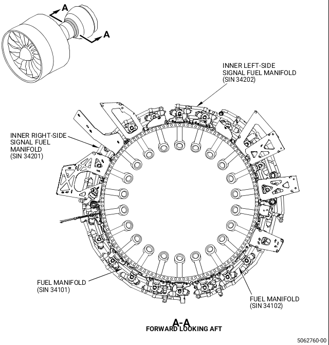
| (2) | Remove the inner right-side signal fuel manifold (SIN 34201, Figure 1), inner left-side signal fuel manifold (SIN 34202), and fuel manifolds (SIN 34101 and SIN 34102). Refer to the GEnx-1B EM, 72-50-00, DISASSEMBLY 001. |
| (3) | Clean the inner right-side signal fuel manifold (SIN 34201, Figure 1), inner left-side signal fuel manifold (SIN 34202), and fuel manifolds (SIN 34101 and SIN 34102). Refer to the GEnx-1B CIR, 72-41-80, CLEANING 002 or to the SPM, 70-21-23, CLEANING METHOD NO. 23 - HAND-WIPE DEGREASING. |
| (4) | Do an inspection of the inner right-side signal fuel manifold (SIN 34201, Figure 1), inner left-side signal fuel manifold (SIN 34202), and fuel manifolds (SIN 34101 and SIN 34102). Refer to the GEnx-1B CIR, 72-41-80, INSPECTIONS 001. |
| NOTE: |
|
| (6) | Assemble the inner right-side signal fuel manifold (SIN 34201, Figure 1), inner left-side signal fuel manifold (SIN 34202), and fuel manifolds (SIN 34101 and SIN 34102). Refer to the GEnx-1B EM, 72-40-00, ASSEMBLY 001, post-GEnx-1B S/B 73-0075 configurations. |
| B. | On-Wing Preparation |
| (1) | Do these steps to make sure that the ENGINE START switch and the FUEL CONTROL switch are not operated: |
| (a) | On the pilot's overhead panel, P5, make sure that the applicable ENGINE START switch is in the NORM position. |
| (b) | Put a DO NOT OPERATE tag on the applicable ENGINE START switch. |
| (c) | On the control stand, P10, make sure that the applicable FUEL CONTROL switch is in the CUT-OFF position. |
| (d) | Put a DO NOT OPERATE tag on the applicable FUEL CONTROL switch. |
| (2) | Make sure that the EEC maintenance (MAINT) switch is in the NORM position. Refer to the GEnx-1B, Boeing 787 AMM, G73-21-05, SOFTWARE OPERATION, DMC-B787-A-G73-21-05-01A-110B-A. |
| (3) | Do these tasks in sequence to safely open the left and right thrust reversers on the applicable engine: |
| (a) | Leading edge slat retraction. Refer to the GEnx-1B, Boeing 787 AMM, 27-81-00, LEADING EDGE SLAT RETRACTION (TASK SELECTION) - OPERATION, DMC-B787-A-27-81-00-27B-110A-A. |
| (b) | Leading edge slat system deactivation. Refer to the GEnx-1B, Boeing 787 AMM, 27-81-00, LEADING EDGE SLAT SYSTEM - DEACTIVATION, DMC-B787-A-27-81-00-24A-510B-A. |
| (c) | Thrust reverser deactivation. Refer to the GEnx-1B, Boeing 787 AMM, G78-31-00, THRUST REVERSER (FOR GROUND MAINTENANCE) - DEACTIVATION, DMC-B787-A-G78-31-00-15H-510B-A. |
| (d) | For the applicable engine, open the left and right fan cowls. Refer to the GEnx-1B, Boeing 787 AMM, G71-11-04, FAN COWL (TASK SELECTION) - OPEN FOR ACCESS, DMC-B787-A-G71-11-04-00B-540A-A and as follows: |
| • |
|
| • |
|
| • |
|
| • |
|
| (e) | For the applicable engine, open the left and right thrust reversers. Refer to the GEnx-1B, Boeing 787 AMM, G78-31-00, THRUST REVERSER (TASK SELECTION ) - OPEN FOR ACCESS, DMC-B787-A-G78-31-00-15B-540A-A and as follows: |
| • |
|
| • |
|
| • |
|
| • |
|
| (f) | Install the protective covers P/N SPL-13475 on the left and right variable frequency starter generator (VFSG) air/oil heat exchangers. |
| (g) | Install the protective cover P/N SPL-13475 on the engine air cooled oil cooler (ACOC). |
| C. | On-Wing Instructions |
| (1) | Do an inspection of the inner right-side signal fuel manifold (SIN 34201, Figure 1), inner left-side signal fuel manifold (SIN 34202), and fuel manifolds (SIN 34101 and SIN 34102) (do not remove them). Refer to the GEnx-1B, Boeing 787 AMM, TUBE AND HOSE INSPECTION CRITERIA AND DAMAGE LIMITS - DETAILED INSPECTION, DMC-B787-A-G70-00-05-00A-280B-A. |
| (2) | If necessary, remove and replace inner right-side signal fuel manifold (SIN 34201, Figure 1), inner left-side signal fuel manifold (SIN 34202), and fuel manifolds (SIN 34101 and SIN 34102). Refer to the GEnx-1B, Boeing 787 AMM, FUEL SIGNAL MANIFOLD - REMOVAL, DMC-B787-A-G73-11-15-00A-520A-A and FUEL SIGNAL MANIFOLD - INSTALLATION, DMC-B787-A-G73-11-15-00A-720A-A. |
| D. | Aircraft Return to Service |
| (1) | Do these tasks in sequence to close the left and right thrust reversers on the applicable engine as follows: |
| (a) | Remove the protective covers P/N SPL-13475 from the left and right VFSG air/oil heat exchangers. |
| (b) | Remove the protective cover P/N SPL-13475 from the ACOC. |
| (c) | For the applicable engine, close the left and right thrust reversers. Refer to the GEnx-1B, Boeing 787 AMM, G78-31-00, THRUST REVERSER (TASK SELECTION) - CLOSE AFTER ACCESS, DMC-B787-A-G78-31-00-15B-740A-A and as follows: |
| • |
|
| • |
|
| • |
|
| • |
|
| (d) | For the applicable engine, close the left and right fan cowls. Refer to the GEnx-1B, Boeing 787 AMM, G71-11-04, FAN COWL (TASK SELECTION) - CLOSE AFTER ACCESS, DMC-B787-A-G71-11-04-00B-740A-A and as follows: |
| • |
|
| • |
|
| • |
|
| • |
|
| (e) | Do the thrust reverser activation. Refer to the GEnx-1B, Boeing 787 AMM, G78-31-00, THRUST REVERSER (AFTER GROUND MAINTENANCE) - ACTIVATION, DMC-B787-A-G78-31-00-15G-730B-A. |
| (f) | Do the leading edge slat system activation. Refer to the GEnx-1B, Boeing 787 AMM, 27-81-00, LEADING EDGE SLAT SYSTEM - ACTIVATION, DMC-B787-A-27-81-00-24A-730B-A. |
| (g) | Do these steps to remove the DO NOT OPERATE tags from the applicable ENGINE START switch and the FUEL CONTROL switch: |
| 1 | On the pilot's overhead panel, P5, remove the DO NOT OPERATE tag from the applicable ENGINE START switch. |
| 2 | On the pilot's aisle control stand, P10, remove the DO NOT OPERATE tag from the applicable FUEL CONTROL switch. |
| 3 | Do an idle leak test (test No. 3). Refer to the GEnx-1B Boeing 787 AMM, G71-00-00, TEST NO.3 - IDLE LEAK TEST, DMC-B787-A-G71-00-00-12A-364A-A. |