| GEnx-1B SERVICE BULLETIN - 73-0093 R00 | Revised: 08/06/2020 | |
| SB 73-0093 R00 ENGINE FUEL AND CONTROL - Fuel Manifold Pigtail Hardware (73-11-40) - Introduction of New Pigtail Brackets | Issued: 08/06/2020 | |
| GEnx-1B SERVICE BULLETIN - 73-0093 R00 | Revised: 08/06/2020 | |
| SB 73-0093 R00 ENGINE FUEL AND CONTROL - Fuel Manifold Pigtail Hardware (73-11-40) - Introduction of New Pigtail Brackets | Issued: 08/06/2020 | |
| GE Designated: -CONFIDENTIAL- | |
| The information contained in this document is GE proprietary information and is disclosed in confidence. It is the property of GE and shall not be used, disclosed to others or reproduced without the express written consent of GE, including, but without limitation, it is not to be used in the creation, manufacture, development, or derivation of any repairs, modifications, spare parts, designs, or configuration changes or to obtain FAA or any other government or regulatory approval to do so. If consent is given for reproduction in whole or in part, this notice and the notice set forth on each page of this document shall appear in any such reproduction in whole or part. | |
| This technical data is considered subject to the Export Administration Regulations (EAR) pursuant to 15 CFR Parts 730-774. Transfer of this data by any means to a Non-U.S. Person, whether in the United States or abroad, without the proper U.S. Government authorization (e.g., License, exemption, NLR, etc.), is strictly prohibited. | |
| Copyright (2020) General Electric Company, U.S.A. |
| 1. | PLANNING INFORMATION |
| A. | Effectivity |
| * * * FOR GEnx-1B64, -1B64/P1, -1B64/P2, -1B67, -1B67/P1, -1B67/P2, -1B70, -1B70/75/P1, -1B70/75/P2, -1B70/P1, -1B70/P2, -1B70C/P1, -1B70C/P2, -1B74/75/P1, -1B74/75/P2, -1B76/P2, -1B76A/P2 |
| This Service Bulletin is applicable to these GEnx-1B engines: |
| • |
|
| This Service Bulletin has been introduced in production to these GEnx-1B engines: |
| • |
|
| These serial numbers are the best available data. |
| The combustor diffuser assemblies P/N 2376M54G01, P/N 2376M54G02, P/N 2376M54G03, P/N 2376M54G04, P/N 2376M54G05, P/N 2376M54G06, P/N 2376M54G07, P/N 2376M54G08, P/N 2376M54G09, P/N 2376M54G10, and P/N 2376M54G11 are affected by this Service Bulletin. |
| B. | Description |
| This Service Bulletin releases new manifold fuel support brackets (pigtail brackets) P/N 2821M79G01, P/N 2821M80G01, P/N 2821M81G01, P/N 2821M82G01, P/N 2821M83G01, P/N 2821M84G01, and P/N 2821M85G01, cushioned loop clamps P/N J1432P06, P/N J1432P08, and P/N J1432P10, and machine bolts P/N AS3236-06 and P/N AS3237-06. |
| This Service Bulletin also provides instructions to install the new pigtail brackets, cushioned loop clamps, and machine bolts to the left side fuel manifold outer segment (fuel manifold) (SIN 34202), left side fuel manifold outer signal enriched segment (fuel manifold) (SIN 34302), left side fuel manifold inner segment (fuel manifold) (SIN 34102), right side fuel manifold outer segment (fuel manifold) (SIN 34201), and right side fuel manifold inner segment (fuel manifold) (SIN 34101). |
| C. | Compliance |
| Category 2 |
| GE recommends that you do this Service Bulletin as soon as possible without effect on revenue service but before 550 engine cycles from the issue date of this Service Bulletin revision. |
| Impact B |
| This recommendation is to address a condition that may result in an Increased Rate of In-Flight Shutdowns (IFSD), Take-Off Aborts (TOA), Air Turn Backs (ATB) or Diversions (DIV). |
| NOTE: |
|
| This Service Bulletin is offered to improve the reliability or performance of your GE product, or to help prevent the occurrence of the event or condition described in this Service Bulletin. If the operator elects not to participate in the bulletin, that decision will be taken into consideration by GE in evaluating future product performance issues that may arise in the operators fleet. |
| D. | Concurrent Requirements |
| None. |
| E. | Reason |
| (1) | Objective: |
| To introduce new parts, improve reliability, and reduce significant events. |
| (2) | Condition: |
| The fuel manifolds (SIN 34101, SIN 34102, SIN 34201, SIN 34202, and SIN 34302) experienced high stress concentration induced by loss of stiffness of the support brackets with age. The fuel manifolds (SIN 34101 and SIN 34201) are mainly affected by this condition. |
| (3) | Cause: |
| High rate fuel couple dynamics, support bracket wear, and repaired manual weld on the fuel manifolds (SIN 34101, SIN 34102, SIN 34201, SIN 34202, and SIN 34302). |
| (4) | Improvement: |
| A new set of pigtail brackets is introduced to prevent high stress concentration on the fuel manifolds (SIN 34101, SIN 34102, SIN 34201, SIN 34202, and SIN 34302), which will address field findings. |
| (5) | Substantiation: |
| Substantiation is by analysis and comparative analysis. |
| F. | Approval |
| The data contained in this Service Bulletin has been reviewed by the FAA or authorized entity representing the FAA and the repair(s) and modification(s) herein comply with the applicable Aviation Regulations and are APPROVED for installation in the model(s) listed in this Service Bulletin. |
| G. | Manpower |
| After you get access to the fuel manifolds (SIN 34101, SIN 34102, SIN 34201, SIN 34202, and SIN 34302), you will need approximately 5 man-hours for each engine or component. |
| H. | Weight and Balance |
| The complete compliance with this Service Bulletin increases weight by 3.40 lb (1.54 kg). |
| I. | References (Use the latest version of these documents) |
| GEnx-1B, Boeing 787 Aircraft Maintenance Manual (AMM) |
| GEK 9250, Commercial Engine Standard Practices Manual (SPM) |
| GEK 112851, GEnx-1B Engine Manual (EM) |
| GEK 112862, GEnx-1B Cleaning, Inspection, and Repair Manual (CIR) |
| GEK 112864, GEnx-1B Engine Illustrated Parts Catalog (EIPC) |
| NOTE: |
|
| J. | Publications Affected |
| GEnx-1B, Boeing 787 Aircraft Maintenance Manual (AMM) |
| GEK 112851, GEnx-1B Engine Manual (EM) |
| GEK 112864, GEnx-1B Engine Illustrated Parts Catalog (EIPC) |
| K. | Interchangeability |
| Qualified interchangeability - Parts added. The pigtail brackets, cushioned loop clamps, and machine bolts must be introduced as a complete set. |
| L. | Software Accomplishment Summary |
| Not applicable. |
| 2. | MATERIAL INFORMATION |
| A. | Material - Price and Availability |
| (1) | Parts necessary to do this Service Bulletin: |
|
||||||||||||||||||||||||||||||||||||||||||||||||||
| NOTE: |
|
| NOTE: |
|
|
| *Part not supplied by GE Engine Services Distribution L.L.C. Procure through local purchase. |
| NP = Not Provisioned |
| NOTE: |
|
| (2) | Other Spare Parts: |
| None. |
| (3) | Consumables: |
|
| B. | Industry Support Information |
| For engines complying to this Service Bulletin 73-0093 (GEnx-1B) on wing, General Electric Company, doing business through its GE Aviation Business Unit (GE) will provide the following commercial support: |
| • |
|
| • |
|
|
| For engines complying to this Service Bulletin 73-0093 (GEnx-1B) in the shop, GE will provide the following commercial support: |
| • |
|
| The back-end spare parts credit may be applied by the customer to future invoices for parts and materials provided by GE Engine Services Distribution LLC. |
| All claims for spare parts credit must be submitted electronically using the myGEAviation.com portal. The back-end spare parts credit is available for customers who complete this Service Bulletin in its entirety before December 31, 2021. All claims must be submitted within 12 months of completion of this Service Bulletin and no later than December 31, 2022. |
| All claims submitted to GE must include the following information: |
| • |
|
| • |
|
| • |
|
| • |
|
| • |
|
| The support offered in this Service Bulletin is contingent on the customer having an active general term agreement (GTA) for the applicable GE engine model. This offer may not be assigned or otherwise transferred to any other party without the written consent of GE. The offer is extended to the customer based on unique facts and circumstances, which the customer hereby acknowledges to be a non-precedent setting between the customer and GE. GEs commitments in this Service Bulletin are subject to the terms and conditions of the current GTA between the customer and GE for the applicable GE engine model. By accepting the commercial support offered by GE under this Service Bulletin, the customer agrees that the Service Bulletin offering satisfies customers commercial needs, and the customer and its officers, agents, partners, subsidiaries, affiliates successors and assigns, forever release, waive and discharge GE, its officers, directors, parents, partners, affiliates, subsidiaries, employees, successors and assigns, from any and all liability solely with respect to subject matter of this Service Bulletin. If compensation becomes available to the customer under guarantees, warranty, Service Bulletins or other engine program consideration, the customer will not receive duplicate compensation but will receive the compensation most beneficial to customer through the single guarantee, warranty, Service Bulletin or other engine program consideration. The terms and conditions of the customers GTA are applicable and remain in effect. |
| Please contact your Customer Support Manager (CSM) with any questions regarding this support. |
| C. | Configuration Chart |
|
| Operation Codes AD=Add RM=Remains |
| Change Codes 5=Qualified interchangeability. Refer to paragraph 1.K., Interchangeability. |
| Support Codes None. |
| D. | Parts Disposition |
| None. |
| E. | Tooling - Price and Availability |
| None. |
| 3. | ACCOMPLISHMENT INSTRUCTIONS |
| A. | On-Wing Removal |
| (1) | Prepare the aircraft as follows: |
| (a) | Do the steps below to make sure that the ENGINE START switch and the FUEL CONTROL switch are not operated: |
| 1 | On the pilot's overhead panel, P5, make sure that the applicable ENGINE START switch is in the NORM position. |
| 2 | Put a DO NOT OPERATE tag on the applicable ENGINE START switch. |
| 3 | On the pilot's aisle control stand, P10, make sure that the applicable FUEL CONTROL switch is in the CUT-OFF position. |
| 4 | Put a DO NOT OPERATE tag on the applicable FUEL CONTROL switch. |
| (b) | Do the tasks below in sequence to safely open the left and right thrust reversers on the applicable engine: |
| 1 | Leading edge slat retraction. Refer to the GEnx-1B, Boeing 787 AMM, 27-81-00, LEADING EDGE SLAT RETRACTION (TASK SELECTION) - OPERATION, DMC-B787-A-27-81-00-27B-110A-A. |
| 2 | Leading edge slat system deactivation. Refer to the GEnx-1B, Boeing 787 AMM, 27-81-00, LEADING EDGE SLAT SYSTEM - DEACTIVATION, DMC-B787-A-27-81-00-24A-510B-A. |
| 3 | Thrust reverser deactivation. Refer to the GEnx-1B, Boeing 787 AMM, G78-31-00, THRUST REVERSER (FOR GROUND MAINTENANCE) - DEACTIVATION, DMC-B787-A-G78-31-00-15H-510B-A. |
| 4 | For the applicable engine, open the left and right fan cowls. Refer to the GEnx-1B, Boeing 787 AMM, G71-11-04, FAN COWL (TASK SELECTION) - OPEN FOR ACCESS, DMC-B787-A-G71-11-04-00B-540A-A and do as follows: |
| • |
|
| • |
|
| • |
|
| • |
|
| 5 | For the applicable engine, open the left and right thrust reversers. Refer to the GEnx-1B, Boeing 787 AMM, G78-31-00, THRUST REVERSER (TASK SELECTION) - OPEN FOR ACCESS, DMC-B787-A-G78-31-00-15B-540A-A and do as follows: |
| • |
|
| • |
|
| • |
|
| • |
|
| (c) | Install protective covers P/N SPL-13475 on the left and right air cooled oil coolers (ACOCs). |
| (d) | Install protective covers P/N SPL-13475 on the left and right variable frequency starter generator (VFSG) air/oil heat exchangers. |
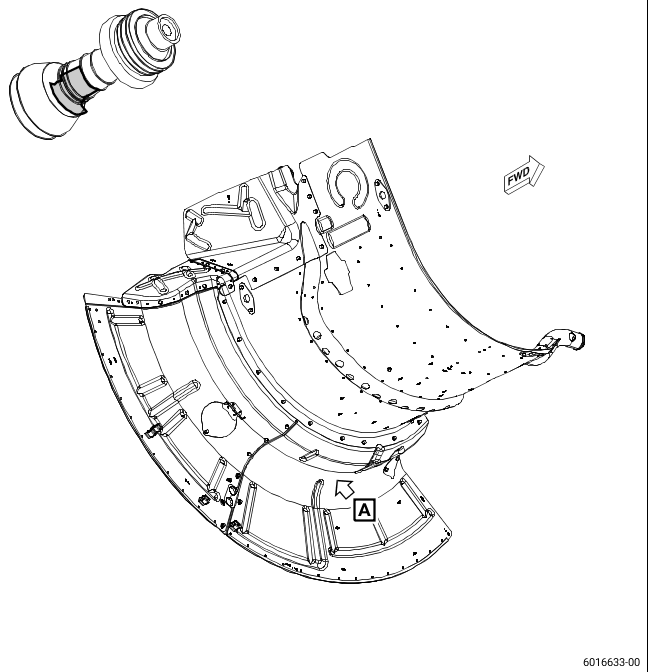
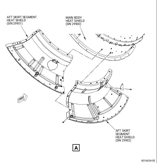
| (2) | Remove the aft skirt segment heat shields (SIN 29901 and SIN 29902, Figure 1) from the main body heat shield (SIN 29900). Refer to the GEnx-1B, Boeing 787 AMM, G73-11-05, FUEL NOZZLE - REMOVAL, DMC-B787-A-G73-11-05-00A-520A-A. |
| B. | In-Shop Removal |
| (1) | Before you start this procedure, read the assembly and disassembly techniques section. Refer to the SPM, 70-10-00, ASSEMBLY AND DISASSEMBLY TECHNIQUES. |
| (2) | Do a general visual inspection of the fuel manifolds (SIN 34101, SIN 34102, SIN 34201, SIN 34202, and SIN 34302). Refer to the GEnx-1B CIR, 72-41-80, INSPECTION 001. |
| (3) | Remove the aft skirt segment heat shields (SIN 29901 and SIN 29902, Figure 1) from the main body heat shield (SIN 29900). Refer to the GEnx-1B EM, 72-00-02, DISASSEMBLY 003, Subtask 72-00-02-030-614. |
| C. | On-Wing Installation |
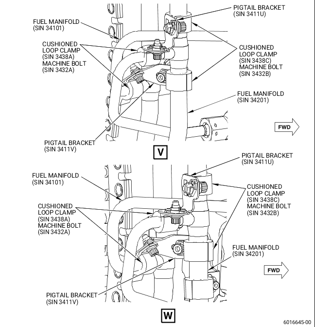
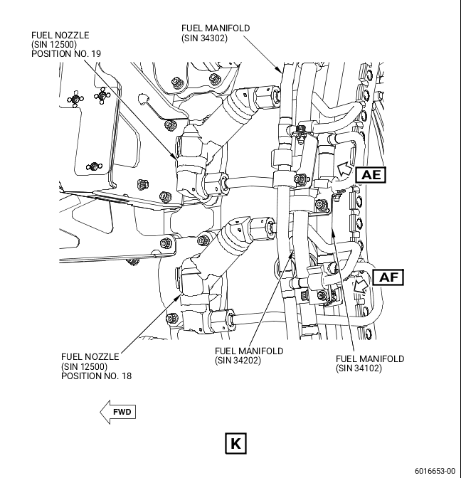
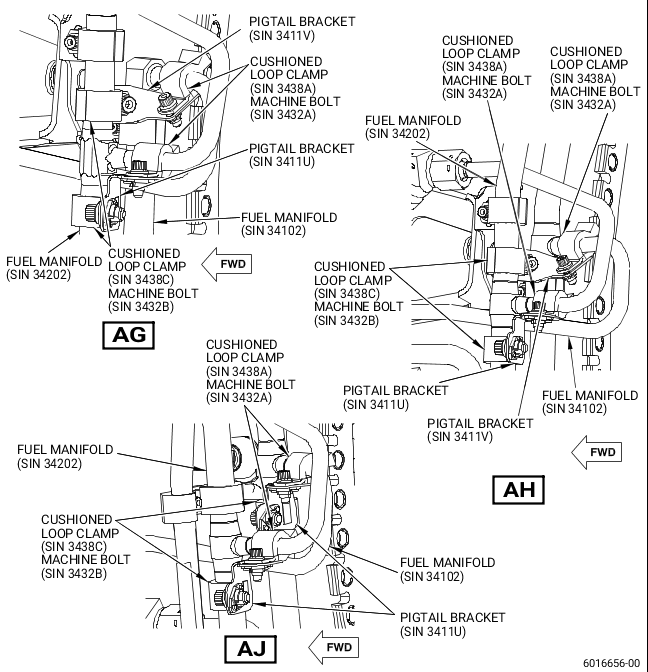
| (1) | Install the new pigtail brackets (SIN 3411U, SIN 3411V, SIN 3411W, SIN 3411Y, SIN 3431J, SIN 3431K, and SIN 3431L) at the fuel manifolds (SIN 34101, SIN 34102, SIN 34201, SIN 34202, and SIN 34302). Refer to Figure 2 and do as follows: |
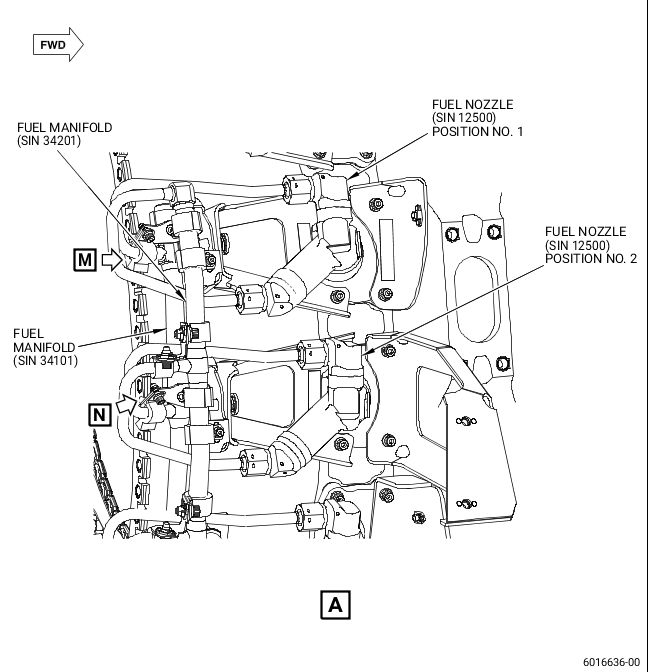
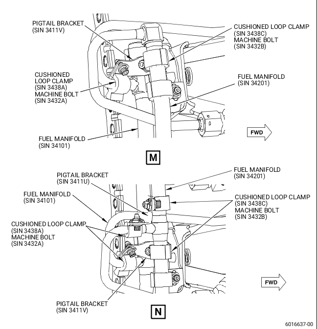
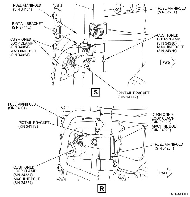
| (a) | Install a new pigtail bracket (SIN 3411V) to attach the fuel manifold (SIN 34201) with a new cushioned loop clamp (SIN 3438C) and a new machine bolt (SIN 3432B) to the pigtail of the fuel manifold (SIN 34101) that connects to the fuel nozzle (SIN 12500) at position No. 1 with a new cushioned loop clamp (SIN 3438A) and a new machine bolt (SIN 3432A). Tighten the machine bolts (SIN 3432A and SIN 3432B) with your hands. |
| (b) | Install a new pigtail bracket (SIN 3411U) to attach the fuel manifold (SIN 34201) with a new cushioned loop clamp (SIN 3438C) and a new machine bolt (SIN 3432B) to the pigtail of the fuel manifold (SIN 34201) that connects to the fuel nozzle (SIN 12500) at position No. 2 with a new cushioned loop clamp (SIN 3438A) and a new machine bolt (SIN 3432A). Tighten the machine bolts (SIN 3432A and SIN 3432B) with your hands. |
| (c) | Install a new pigtail bracket (SIN 3411V) to attach the fuel manifold (SIN 34201) with a new cushioned loop clamp (SIN 3438C) and a new machine bolt (SIN 3432B) to the pigtail of the fuel manifold (SIN 34101) that connects to the fuel nozzle (SIN 12500) at position No. 2 with a new cushioned loop clamp (SIN 3438A) and a new machine bolt (SIN 3432A). Tighten the machine bolts (SIN 3432A and SIN 3432B) with your hands. |
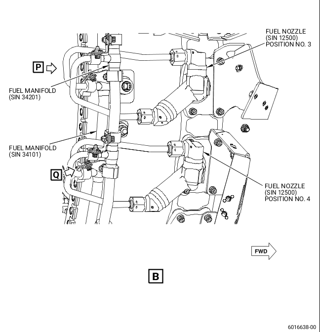
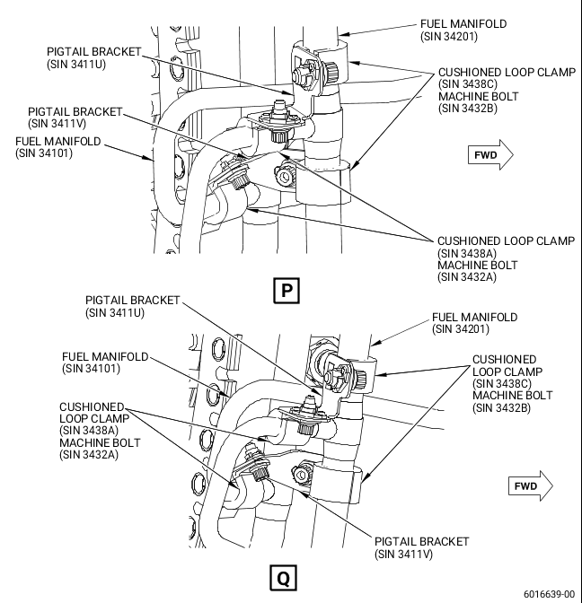
| (d) | Install a new pigtail bracket (SIN 3411U) to attach the fuel manifold (SIN 34201) with a new cushioned loop clamp (SIN 3438C) and a new machine bolt (SIN 3432B) to the pigtail of the fuel manifold (SIN 34201) that connects to the fuel nozzle (SIN 12500) at position No. 3 with a new cushioned loop clamp (SIN 3438A) and a new machine bolt (SIN 3432A). Tighten the machine bolts (SIN 3432A and SIN 3432B) with your hands. |
| (e) | Install a new pigtail bracket (SIN 3411V) to attach the fuel manifold (SIN 34201) with a new cushioned loop clamp (SIN 3438C) and a new machine bolt (SIN 3432B) to the pigtail of the fuel manifold (SIN 34101) that connects to the fuel nozzle (SIN 12500) at position No. 3 with a new cushioned loop clamp (SIN 3438A) and a new machine bolt (SIN 3432A). Tighten the machine bolts (SIN 3432A and SIN 3432B) with your hands. |
| (f) | Install a new pigtail bracket (SIN 3411U) to attach the fuel manifold (SIN 34201) with a new cushioned loop clamp (SIN 3438C) and a new machine bolt (SIN 3432B) to the pigtail of the fuel manifold (SIN 34201) that connects to the fuel nozzle (SIN 12500) at position No. 4 with a new cushioned loop clamp (SIN 3438A) and a new machine bolt (SIN 3432A). Tighten the machine bolts (SIN 3432A and SIN 3432B) with your hands. |
| (g) | Install a new pigtail bracket (SIN 3411V) to attach the fuel manifold (SIN 34201) with a new cushioned loop clamp (SIN 3438C) and a new machine bolt (SIN 3432B) to the pigtail of the fuel manifold (SIN 34101) that connects to the fuel nozzle (SIN 12500) at position No. 4 with a new cushioned loop clamp (SIN 3438A) and a new machine bolt (SIN 3432A). Tighten the machine bolts (SIN 3432A and SIN 3432B) with your hands. |
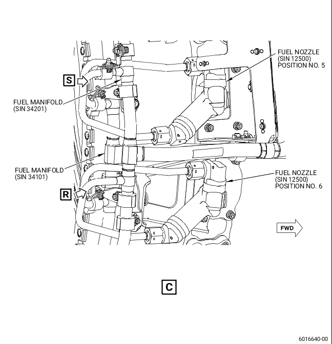
| (h) | Install a new pigtail bracket (SIN 3411U) to attach the fuel manifold (SIN 34201) with a new cushioned loop clamp (SIN 3438C) and a new machine bolt (SIN 3432B) to the pigtail of the fuel manifold (SIN 34201) that connects to the fuel nozzle (SIN 12500) at position No. 5 with a new cushioned loop clamp (SIN 3438A) and a new machine bolt (SIN 3432A). Tighten the machine bolts (SIN 3432A and SIN 3432B) with your hands. |
| (i) | Install a new pigtail bracket (SIN 3411V) to attach the fuel manifold (SIN 34201) with a new cushioned loop clamp (SIN 3438C) and a new machine bolt (SIN 3432B) to the pigtail of the fuel manifold (SIN 34101) that connects to the fuel nozzle (SIN 12500) at position No. 5 with a new cushioned loop clamp (SIN 3438A) and a new machine bolt (SIN 3432A). Tighten the machine bolts (SIN 3432A and SIN 3432B) with your hands. |
| (j) | Install a new pigtail bracket (SIN 3411V) to attach the fuel manifold (SIN 34201) with a new cushioned loop clamp (SIN 3438C) and a new machine bolt (SIN 3432B) to the pigtail of the fuel manifold (SIN 34101) that connects to the fuel nozzle (SIN 12500) at position No. 6 with a new cushioned loop clamp (SIN 3438A) and a new machine bolt (SIN 3432A). Tighten the machine bolts (SIN 3432A and SIN 3432B) with your hands. |
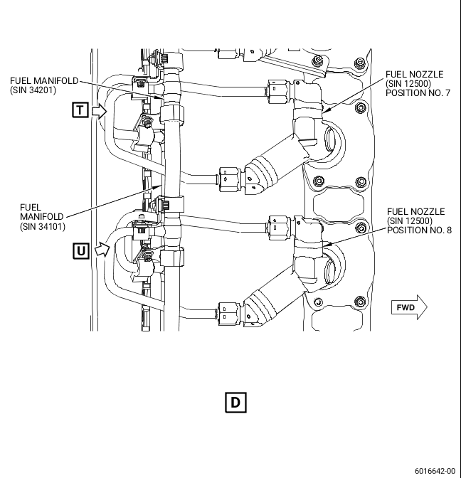
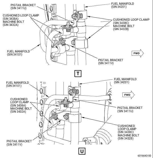
| (k) | Install a new pigtail bracket (SIN 3411U) to attach the fuel manifold (SIN 34201) with a new cushioned loop clamp (SIN 3438C) and a new machine bolt (SIN 3432B) to the pigtail of the fuel manifold (SIN 34201) that connects to the fuel nozzle (SIN 12500) at position No. 7 with a new cushioned loop clamp (SIN 3438A) and a new machine bolt (SIN 3432A). Tighten the machine bolts (SIN 3432A and SIN 3432B) with your hands. |
| (l) | Install a new pigtail bracket (SIN 3411V) to attach the fuel manifold (SIN 34201) with a new cushioned loop clamp (SIN 3438C) and a new machine bolt (SIN 3432B) to the pigtail of the fuel manifold (SIN 34101) that connects to the fuel nozzle (SIN 12500) at position No. 7 with a new cushioned loop clamp (SIN 3438A) and a new machine bolt (SIN 3432A). Tighten the machine bolts (SIN 3432A and SIN 3432B) with your hands. |
| (m) | Install a new pigtail bracket (SIN 3411U) to attach the fuel manifold (SIN 34201) with a new cushioned loop clamp (SIN 3438C) and a new machine bolt (SIN 3432B) to the pigtail of the fuel manifold (SIN 34201) that connects to the fuel nozzle (SIN 12500) at position No. 8 with a new cushioned loop clamp (SIN 3438A) and a new machine bolt (SIN 3432A). Tighten the machine bolts (SIN 3432A and SIN 3432B) with your hands. |
| (n) | Install a new pigtail bracket (SIN 3411V) to attach the fuel manifold (SIN 34201) with a new cushioned loop clamp (SIN 3438C) and a new machine bolt (SIN 3432B) to the pigtail of the fuel manifold (SIN 34101) that connects to the fuel nozzle (SIN 12500) at position No. 8 with a new cushioned loop clamp (SIN 3438A) and a new machine bolt (SIN 3432A). Tighten the machine bolts (SIN 3432A and SIN 3432B) with your hands. |
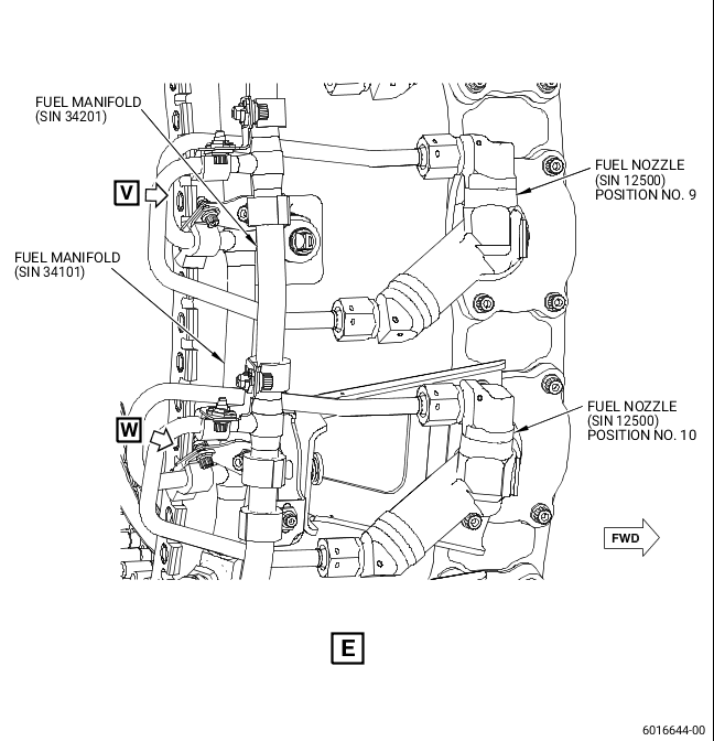
| (o) | Install a new pigtail bracket (SIN 3411U) to attach the fuel manifold (SIN 34201) with a new cushioned loop clamp (SIN 3438C) and a new machine bolt (SIN 3432B) to the pigtail of the fuel manifold (SIN 34201) that connects to the fuel nozzle (SIN 12500) at position No. 9 with a new cushioned loop clamp (SIN 3438A) and a new machine bolt (SIN 3432A). Tighten the machine bolts (SIN 3432A and SIN 3432B) with your hands. |
| (p) | Install a new pigtail bracket (SIN 3411V) to attach the fuel manifold (SIN 34201) with a new cushioned loop clamp (SIN 3438C) and a new machine bolt (SIN 3432B) to the pigtail of the fuel manifold (SIN 34101) that connects to the fuel nozzle (SIN 12500) at position No. 9 with a new cushioned loop clamp (SIN 3438A) and a new machine bolt (SIN 3432A). Tighten the machine bolts (SIN 3432A and SIN 3432B) with your hands. |
| (q) | Install a new pigtail bracket (SIN 3411U) to attach the fuel manifold (SIN 34201) with a new cushioned loop clamp (SIN 3438C) and a new machine bolt (SIN 3432B) to the pigtail of the fuel manifold (SIN 34201) that connects to the fuel nozzle (SIN 12500) at position No. 10 with a new cushioned loop clamp (SIN 3438A) and a new machine bolt (SIN 3432A). Tighten the machine bolts (SIN 3432A and SIN 3432B) with your hands. |
| (r) | Install a new pigtail bracket (SIN 3411V) to attach the fuel manifold (SIN 34201) with a new cushioned loop clamp (SIN 3438C) and a new machine bolt (SIN 3432B) to the pigtail of the fuel manifold (SIN 34101) that connects to the fuel nozzle (SIN 12500) at position No. 10 with a new cushioned loop clamp (SIN 3438A) and a new machine bolt (SIN 3432A). Tighten the machine bolts (SIN 3432A and SIN 3432B) with your hands. |
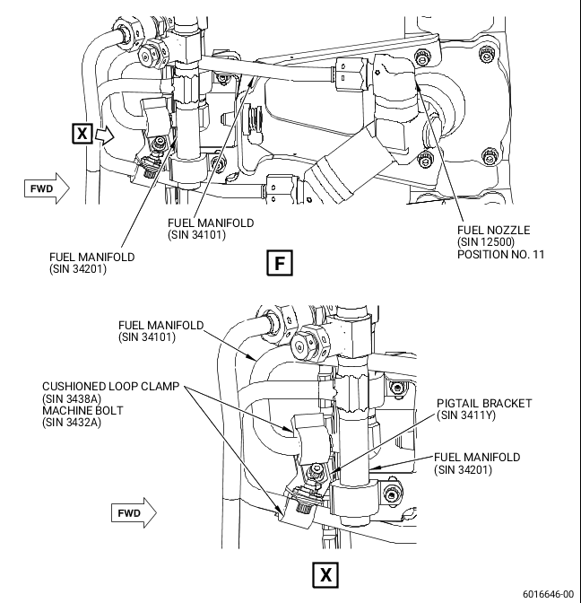
| (s) | Install a new pigtail bracket (SIN 3411Y) to attach the pigtail of the fuel manifold (SIN 34201), that connects to the fuel nozzle (SIN 12500) at position No. 11, with a new cushioned loop clamp (SIN 3438A) and a new machine bolt (SIN 3432A) to the pigtail of the fuel manifold (SIN 34101) that connects to the fuel nozzle (SIN 12500) at position No. 11 with a new cushioned loop clamp (SIN 3438A) and a new machine bolt (SIN 3432A). Tighten the machine bolts (SIN 3432A) with your hands. |
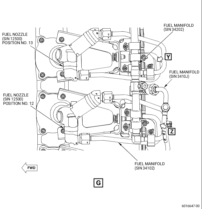
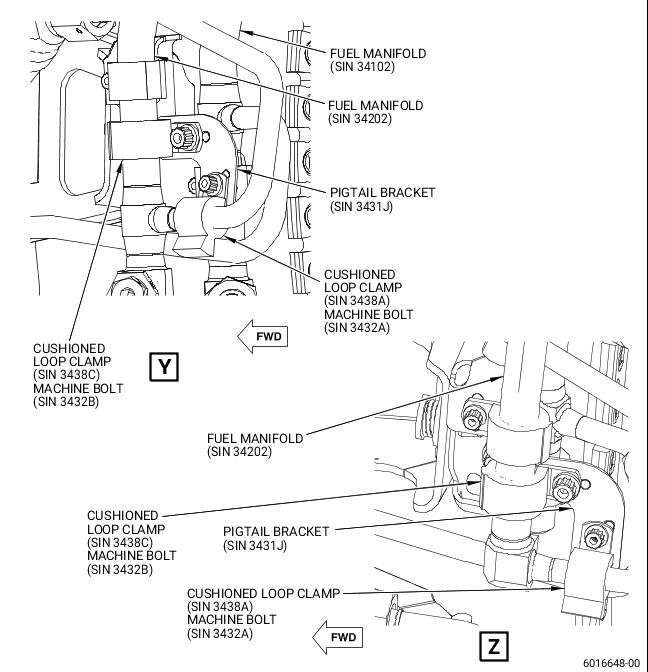
| (t) | Install a new pigtail bracket (SIN 3431J) to attach the fuel manifold (SIN 34202) with a new cushioned loop clamp (SIN 3438C) and a new machine bolt (SIN 3432B) to the pigtail of the fuel manifold (SIN 34202) that connects to the fuel nozzle (SIN 12500) at position No. 12 with a new cushioned loop clamp (SIN 3438A) and a new machine bolt (SIN 3432A). Tighten the machine bolts (SIN 3432A and SIN 3432B) with your hands. |
| (u) | Install a new pigtail bracket (SIN 3431J) to attach the fuel manifold (SIN 34202) with a new cushioned loop clamp (SIN 3438C) and a new machine bolt (SIN 3432B) to the pigtail of the fuel manifold (SIN 34202) that connects to the fuel nozzle (SIN 12500) at position No. 13 with a new cushioned loop clamp (SIN 3438A) and a new machine bolt (SIN 3432A). Tighten the machine bolts (SIN 3432A and SIN 3432B) with your hands. |
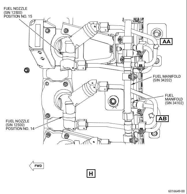
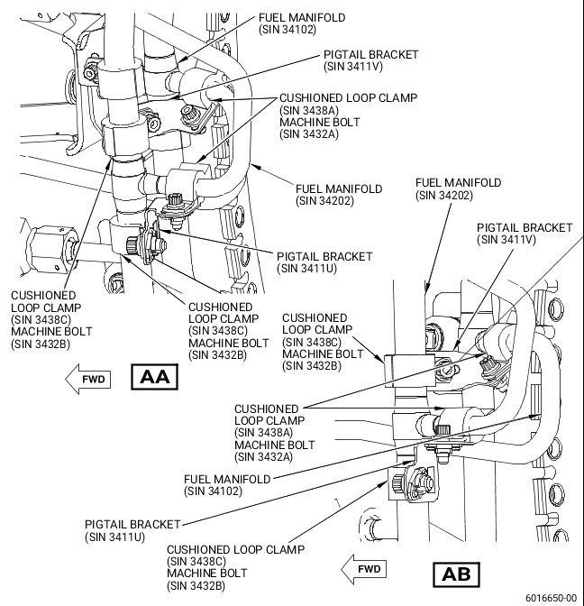
| (v) | Install a new pigtail bracket (SIN 3411U) to attach the fuel manifold (SIN 34202) with a new cushioned loop clamp (SIN 3438C) and a new machine bolt (SIN 3432B) to the pigtail of the fuel manifold (SIN 34202) that connects to the fuel nozzle (SIN 12500) at position No. 14 with a new cushioned loop clamp (SIN 3438A) and a new machine bolt (SIN 3432A). Tighten the machine bolts (SIN 3432A and SIN 3432B) with your hands. |
| (w) | Install a new pigtail bracket (SIN 3411V) to attach the fuel manifold (SIN 34202) with a new cushioned loop clamp (SIN 3438C) and a new machine bolt (SIN 3432B) to the pigtail of the fuel manifold (SIN 34102) that connects to the fuel nozzle (SIN 12500) at position No. 14 with a new cushioned loop clamp (SIN 3438A) and a new machine bolt (SIN 3432A). Tighten the machine bolts (SIN 3432A and SIN 3432B) with your hands. |
| (x) | Install a new pigtail bracket (SIN 3411U) to attach the fuel manifold (SIN 34202) with a new cushioned loop clamp (SIN 3438C) and a new machine bolt (SIN 3432B) to the pigtail of the fuel manifold (SIN 34202) that connects to the fuel nozzle (SIN 12500) at position No. 15 with a new cushioned loop clamp (SIN 3438A) and a new machine bolt (SIN 3432A). Tighten the machine bolts (SIN 3432A and SIN 3432B) with your hands. |
| (y) | Install a new pigtail bracket (SIN 3411V) to attach the fuel manifold (SIN 34202) with a new cushioned loop clamp (SIN 3438C) and a new machine bolt (SIN 3432B) to the pigtail of the fuel manifold (SIN 34102) that connects to the fuel nozzle (SIN 12500) at position No. 15 with a new cushioned loop clamp (SIN 3438A) and a new machine bolt (SIN 3432A). Tighten the machine bolts (SIN 3432A and SIN 3432B) with your hands. |
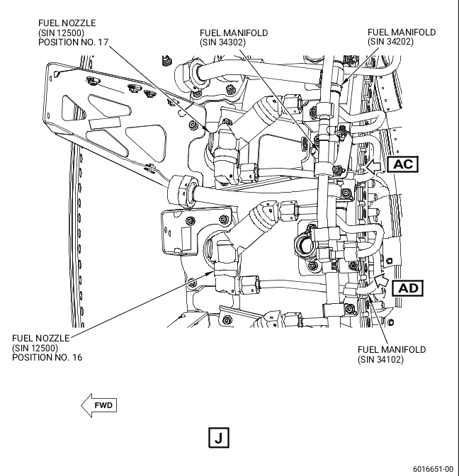
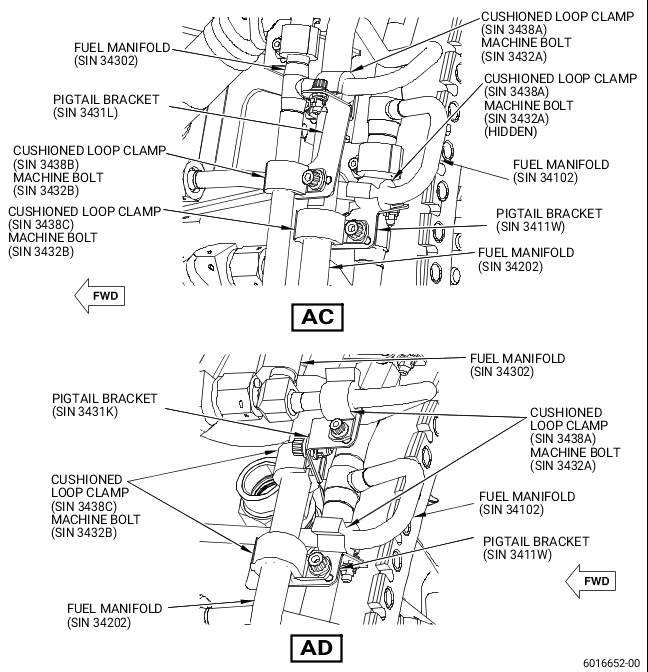
| (z) | Install a new pigtail bracket (SIN 3411W) to attach the fuel manifold (SIN 34202) with a new cushioned loop clamp (SIN 3438C) and a new machine bolt (SIN 3432B) to the pigtail of the fuel manifold (SIN 34102) that connects to the fuel nozzle (SIN 12500) at position No. 16 with a new cushioned loop clamp (SIN 3438A) and a new machine bolt (SIN 3432A). Tighten the machine bolts (SIN 3432A and SIN 3432B) with your hands. |
| (aa) | Install a new pigtail bracket (SIN 3431K) to attach the fuel manifold (SIN 34202) with a new cushioned loop clamp (SIN 3438C) and a new machine bolt (SIN 3432B) to the pigtail of the fuel manifold (SIN 34302) that connects to the fuel nozzle (SIN 12500) at position No. 16 with a new cushioned loop clamp (SIN 3438A) and a new machine bolt (SIN 3432A). Tighten the machine bolts (SIN 3432A and SIN 3432B) with your hands. |
| (ab) | Install a new pigtail bracket (SIN 3411W) to attach the fuel manifold (SIN 34202) with a new cushioned loop clamp (SIN 3438C) and a new machine bolt (SIN 3432B) to the pigtail of the fuel manifold (SIN 34102) that connects to the fuel nozzle (SIN 12500) at position No. 17 with a new cushioned loop clamp (SIN 3438A) and a new machine bolt (SIN 3432A). Tighten the machine bolts (SIN 3432A and SIN 3432B) with your hands. |
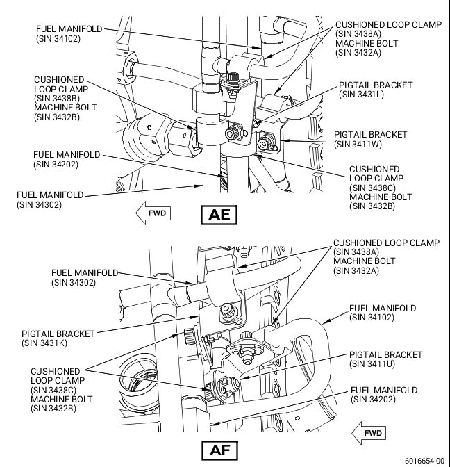
| (ac) | Install a new pigtail bracket (SIN 3431L) to attach the fuel manifold (SIN 34302) with a new cushioned loop clamp (SIN 3438B) and a new machine bolt (SIN 3432B) to the pigtail of the fuel manifold (SIN 34302) that connects to the fuel nozzle (SIN 12500) at position No. 17 with a new cushioned loop clamp (SIN 3438A) and a new machine bolt (SIN 3432A). Tighten the machine bolts (SIN 3432A and SIN 3432B) with your hands. |
| (ad) | Install a new pigtail bracket (SIN 3411U) to attach the fuel manifold (SIN 34102) with a new cushioned loop clamp (SIN 3438C) and a new machine bolt (SIN 3432B) to the pigtail of the fuel manifold (SIN 34102) that connects to the fuel nozzle (SIN 12500) at position No. 18 with a new cushioned loop clamp (SIN 3438A) and a new machine bolt (SIN 3432A). Tighten the machine bolts (SIN 3432A and SIN 3432B) with your hands. |
| (ae) | Install a new pigtail bracket (SIN 3431K) to attach the fuel manifold (SIN 34202) with a new cushioned loop clamp (SIN 3438C) and a new machine bolt (SIN 3432B) to the pigtail of the fuel manifold (SIN 34302) that connects to the fuel nozzle (SIN 12500) at position No. 18 with a new cushioned loop clamp (SIN 3438A) and a new machine bolt (SIN 3432A). Tighten the machine bolts (SIN 3432A and SIN 3432B) with your hands. |
| (af) | Install a new pigtail bracket (SIN 3411W) to attach the fuel manifold (SIN 34202) with a new cushioned loop clamp (SIN 3438C) and a new machine bolt (SIN 3432B) to the pigtail of the fuel manifold (SIN 34102) that connects to the fuel nozzle (SIN 12500) at position No. 19 with a new cushioned loop clamp (SIN 3438A) and a new machine bolt (SIN 3432A). Tighten the machine bolts (SIN 3432A and SIN 3432B) with your hands. |
| (ag) | Install a new pigtail bracket (SIN 3431L) to attach the fuel manifold (SIN 34302) with a new cushioned loop clamp (SIN 3438B) and a new machine bolt (SIN 3432B) to the pigtail of the fuel manifold (SIN 34302) that connects to the fuel nozzle (SIN 12500) at position No. 19 with a new cushioned loop clamp (SIN 3438A) and a new machine bolt (SIN 3432A). Tighten the machine bolts (SIN 3432A and SIN 3432B) with your hands. |
| (ah) | Install a new pigtail bracket (SIN 3411U) to attach the fuel manifold (SIN 34202) with a new cushioned loop clamp (SIN 3438C) and a new machine bolt (SIN 3432B) to the pigtail of the fuel manifold (SIN 34202) that connects to the fuel nozzle (SIN 12500) at position No. 20 with a new cushioned loop clamp (SIN 3438A) and a new machine bolt (SIN 3432A). Tighten the machine bolts (SIN 3432A and SIN 3432B) with your hands. |
| (ai) | Install a new pigtail bracket (SIN 3411U) to attach the fuel manifold (SIN 34102) with a new cushioned loop clamp (SIN 3438C) and a new machine bolt (SIN 3432B) to the pigtail of the fuel manifold (SIN 34102) that connects to the fuel nozzle (SIN 12500) at position No. 20 with a new cushioned loop clamp (SIN 3438A) and a new machine bolt (SIN 3432A). Tighten the machine bolts (SIN 3432A and SIN 3432B) with your hands. |
| (aj) | Install a new pigtail bracket (SIN 3411U) to attach the fuel manifold (SIN 34202) with a new cushioned loop clamp (SIN 3438C) and a new machine bolt (SIN 3432B) to the pigtail of the fuel manifold (SIN 34202) that connects to the fuel nozzle (SIN 12500) at position No. 21 with a new cushioned loop clamp (SIN 3438A) and a new machine bolt (SIN 3432A). Tighten the machine bolts (SIN 3432A and SIN 3432B) with your hands. |
| (ak) | Install a new pigtail bracket (SIN 3411V) to attach the fuel manifold (SIN 34202) with a new cushioned loop clamp (SIN 3438C) and a new machine bolt (SIN 3432B) to the pigtail of the fuel manifold (SIN 34102) that connects to the fuel nozzle (SIN 12500) at position No. 21 with a new cushioned loop clamp (SIN 3438A) and a new machine bolt (SIN 3432A). Tighten the machine bolts (SIN 3432A and SIN 3432B) with your hands. |
| (al) | Install a new pigtail bracket (SIN 3411U) to attach the fuel manifold (SIN 34202) with a new cushioned loop clamp (SIN 3438C) and a new machine bolt (SIN 3432B) to the pigtail of the fuel manifold (SIN 34202) that connects to the fuel nozzle (SIN 12500) at position No. 22 with a new cushioned loop clamp (SIN 3438A) and a new machine bolt (SIN 3432A). Tighten the machine bolts (SIN 3432A and SIN 3432B) with your hands. |
| (am) | Install a new pigtail bracket (SIN 3411V) to attach the fuel manifold (SIN 34202) with a new cushioned loop clamp (SIN 3438C) and a new machine bolt (SIN 3432B) to the pigtail of the fuel manifold (SIN 34102) that connects to the fuel nozzle (SIN 12500) at position No. 22 with a new cushioned loop clamp (SIN 3438A) and a new machine bolt (SIN 3432A). Tighten the machine bolts (SIN 3432A and SIN 3432B) with your hands. |
| (an) | Torque the machine bolts (SIN 3432A and SIN 3432B) to 51 to 59 lb in. (5.7 to 6.6 Nm). |
| (2) | If one or more cushioned loop clamps (SIN 3438A, SIN 3438B, or SIN 3438C, Figure 2) are loose after the final torque procedure, do as follows: |
| (a) | Remove the loose cushioned loop clamps (SIN 3438A, SIN 3438B, or SIN 3438C) and the related machine bolts (SIN 3432A or SIN 3432B). |
| WARNING: |
|
| (b) | Clean the related fuel manifold (SIN 34101, SIN 34102, SIN 34201, SIN 34202, or SIN 34302) where the cushioned loop clamps (SIN 3438A, SIN 3438B, or SIN 3438C) were attached with C04-035 isopropyl alcohol or equivalent and let it dry. |
| (c) | Make sure that the surface of the related fuel manifold (SIN 34101, SIN 34102, SIN 34201, SIN 34202, or SIN 34302) are free of dirt, grease, or other unwanted material that could affect the correct adhesion of the tape. |
| (d) | Put a continuous piece of C10-225 PTFE coated tape or C10-230 PTFE tape around the related fuel manifold (SIN 34101, SIN 34102, SIN 34201, SIN 34202, or SIN 34302). Apply sufficient layers of C10-225 PTFE coated tape or C10-230 PTFE tape to tightly attach the related fuel manifold (SIN 34101, SIN 34102, SIN 34201, SIN 34202, or SIN 34302) with the correct cushioned loop clamp (SIN 3438A, SIN 3438B, or SIN 3438C). |
| (e) | Make sure that the C10-225 PTFE coated tape or C10-230 PTFE tape is aligned. |
| (f) | Push the C10-225 PTFE coated tape or C10-230 PTFE tape tightly to complete the contact around the related fuel manifold (SIN 34101, SIN 34102, SIN 34201, SIN 34202, or SIN 34302) diameter. |
| (g) | Do a visual inspection of the C10-225 PTFE coated tape or C10-230 PTFE tape for correct bond. There must be no visual evidence of unbonded areas between the tape and the related fuel manifold (SIN 34101, SIN 34102, SIN 34201, SIN 34202, or SIN 34302). |
| (h) | Do a visual inspection of the C10-225 PTFE coated tape or C10-230 PTFE tape to make sure that there are no visual signs of tears and wrinkles in the tape. Tears and wrinkles are not permitted. |
| (i) | Install the removed cushioned loop clamp (SIN 3438A, SIN 3438B, or SIN 3438C) and the related machine bolt (SIN 3432A or SIN 3432B) back. |
| (j) | Torque the machine bolts (SIN 3432A and SIN 3432B) to 51 to 59 lb in. (5.7 to 6.6 Nm). |
| (3) | Install the aft skirt segment heat shields (SIN 29901 and SIN 29902, Figure 1) in the main body heat shield (SIN 29900). Refer to the GEnx-1B, Boeing 787 AMM, G73-11-05, FUEL NOZZLE - INSTALLATION, DMC-B787-A-G73-11-05-00A-720A-A. |
| (4) | Return the aircraft to service as follows: |
| (a) | Remove the protective covers P/N SPL-13475 from the left and right VFSG air/oil heat exchangers. |
| (b) | Remove the protective covers P/N SPL-13475 from the left and right ACOCs. |
| (c) | Do the tasks below in sequence to close the left and right thrust reversers on the applicable engine: |
| 1 | For the applicable engine, close the left and right thrust reversers. Refer to the GEnx-1B, Boeing 787 AMM, G73-11-05,, G78-31-00, THRUST REVERSER (TASK SELECTION) - CLOSE AFTER ACCESS, DMC-B787-A-G78-31-00-15B-740A-A and the list that follows: |
| • |
|
| • |
|
| • |
|
| • |
|
| 2 | For the applicable engine, close the left and right fan cowls. Refer to the GEnx-1B, Boeing 787 AMM, G71-11-04, FAN COWL (TASK SELECTION) - CLOSE AFTER ACCESS, DMC-B787-A-G71-11-04-00B-740A-A and the list that follows: |
| • |
|
| • |
|
| • |
|
| • |
|
| 3 | Do the thrust reverser activation. Refer to the GEnx-1B, Boeing 787 AMM, G78-31-00, THRUST REVERSER (AFTER GROUND MAINTENANCE) - ACTIVATION, DMC-B787-A-G78-31-00-15G-730B-A. |
| 4 | Do the leading edge slat system activation. Refer to the GEnx-1B, Boeing 787 AMM, , G78-31-00, 27-81-00, LEADING EDGE SLAT SYSTEM - ACTIVATION, DMC-B787-A-27-81-00-24A-730B-A. |
| (d) | Do the steps below to remove the DO NOT OPERATE tags from the applicable ENGINE START switch and the FUEL CONTROL switch: |
| 1 | On the pilot's overhead panel, P5, remove the DO NOT OPERATE tag from the applicable ENGINE START switch. |
| 2 | On the pilot's aisle control stand, P10, remove the DO NOT OPERATE tag from the applicable FUEL CONTROL switch. |
| D. | In-Shop Installation |
| (1) | Install the new pigtail brackets (SIN 3411U, SIN 3411V, SIN 3411W, SIN 3411Y, SIN 3431J, SIN 3431K, and SIN 3431L) at the fuel manifolds (SIN 34101, SIN 34102, SIN 34201, SIN 34202, and SIN 34302). Refer to Figure 2 of this Service Bulletin and the GEnx-1B EM, 72-40-00, ASSEMBLY 001, CONFIG 01, Subtask 72-40-00-440-206, or CONFIG 02, Subtask 72-40-00-440-207. |
| (2) | Install the aft skirt segment heat shields (SIN 29901 and SIN 29902, Figure 1) in the main body heat shield (SIN 29900). Refer to the GEnx-1B EM, 72-00-02, ASSEMBLY 004, CONFIG 01, Subtask 72-00-02-440-452 or CONFIG 02, Subtask 72-00-02-440-401. |