| GEnx-1B SERVICE BULLETIN - 75-0029 R02 | Revised: 03/18/2024 | |
| SB 75-0029 R02 AIR - HPT ACC Manifolds (75-24-30) - HPT Air Manifolds Connector Improvement | Issued: 02/06/2018 | |
| GEnx-1B SERVICE BULLETIN - 75-0029 R02 | Revised: 03/18/2024 | |
| SB 75-0029 R02 AIR - HPT ACC Manifolds (75-24-30) - HPT Air Manifolds Connector Improvement | Issued: 02/06/2018 | |
| GE Designated: -CONFIDENTIAL- | |
| The information contained in this document is GE proprietary information and is disclosed in confidence. It is the property of GE and shall not be used, disclosed to others or reproduced without the express written consent of GE, including, but without limitation, it is not to be used in the creation, manufacture, development, or derivation of any repairs, modifications, spare parts, designs, or configuration changes or to obtain FAA or any other government or regulatory approval to do so. If consent is given for reproduction in whole or in part, this notice and the notice set forth on each page of this document shall appear in any such reproduction in whole or part. | |
| This technical data is considered subject to the Export Administration Regulations (EAR) pursuant to 15 CFR Parts 730-774. Transfer of this data by any means to a Non-U.S. Person, whether in the United States or abroad, without the proper U.S. Government authorization (e.g., License, exemption, NLR, etc.), is strictly prohibited. | |
| Copyright (2024) General Electric Company, U.S.A. |
| TRANSMITTAL INFORMATION |
| REVISION 2 TO SERVICE BULLETIN 75-0029 |
| Revision 2 is issued to update paragraphs 2., MATERIAL INFORMATION and 3., ACCOMPLISHMENT INSTRUCTIONS. |
| Revision 1 was issued June 14, 2019. The original was issued February 06, 2018. Revision bars in the left margin identify changes. |
| 1. | PLANNING INFORMATION |
| A. | Effectivity |
| * * * FOR GEnx-1B64, -1B64/P1, -1B64/P2, -1B67, -1B67/P1, -1B67/P2, -1B70, -1B70/75/P1, -1B70/75/P2, -1B70/P1, -1B70/P2, -1B70C/P1, -1B70C/P2, -1B74/75/P1, -1B74/75/P2, -1B76/P2, -1B76A/P2 |
| This Service Bulletin is applicable to all GEnx-1B engines. |
| This Service Bulletin has been introduced in production to these GEnx-1B engines: |
| • |
|
| These serial numbers are the best available data. |
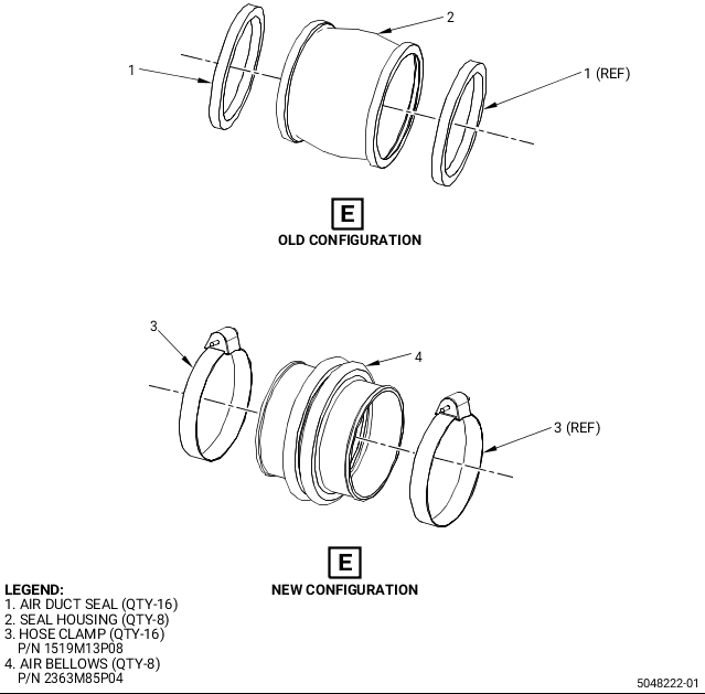
| The air duct seal P/N 1682M91P08 and seal housing P/N 2406M07P01 are affected by this Service Bulletin. |
| B. | Description |
| This Service Bulletin provides improvement in the high pressure turbine (HPT) air manifold connectors by replacing the affected metallic seal housing and silicone air duct seal with fire-proof fabric reinforced silicone rubber low pressure turbine (LPT) active clearance control (ACC) air bellows (air bellows) P/N 2363M85P04 and low pressure hose clamp (hose clamp) P/N 1519M13P08. |
| C. | Compliance |
| Category 3 |
| GE recommends that you do this Service Bulletin at the next shop visit of the engine/module. |
| Impact E |
| This recommendation is to improve the cost of ownership, reduce maintenance requirements or is a product improvement. |
| NOTE: |
|
| This Service Bulletin is offered to improve the reliability or performance of your GE product, or to help prevent the occurrence of the event or condition described in this Service Bulletin. If the operator elects not to participate in the bulletin, that decision will be taken into consideration by GE in evaluating future product performance issues that may arise in the operator’s fleet. |
| D. | Concurrent Requirements |
| None. |
| E. | Reason |
| (1) | Objective: |
| To introduce new parts and improve maintainability. |
| (2) | Condition: |
| The present configuration has field findings of metal-to-metal wear against the HPT air manifolds, which has been fixed by applying room temperature vulcanized (RTV) silicone at the interface between the seal housings and HPT air manifolds. |
| (3) | Cause: |
| The metallic seal housing shape has led to seal housing and HPT air manifolds wear in the field. |
| (4) | Improvement: |
| Introduction of proposed rubber air bellows and hose clamp configuration standardizes the hardware of the HPT ACC and LPT ACC and improves manufacturing efficiency by eliminating the assembly steps required to apply RTV silicone on the seal housing. This change also reduces the clamping load to a value that will not deform the duct but sufficient to prevent the rubber bellows from sliding. |
| (5) | Substantiation: |
| Substantiation is by comparative analysis. |
| F. | Approval |
| The data contained in this Service Bulletin has been reviewed by the FAA or authorized entity representing the FAA and the repair(s) and modification(s) herein comply with the applicable Aviation Regulations and are APPROVED for installation in the model(s) listed in this Service Bulletin. |
| G. | Manpower |
| No additional man-hours are required to comply with this Service Bulletin. |
| H. | Weight and Balance |
| Weight and balance are not changed. |
| I. | References (Use the latest version of these documents) |
| GEnx-1B, Boeing 787 Aircraft Maintenance Manual (AMM) |
| GEK 9250, Commercial Engine Standard Practices Manual (SPM) |
| GEK 112851, GEnx-1B Engine Manual (EM) |
| GEK 112864, GEnx-1B Engine Illustrated Parts Catalog (EIPC) |
| GEnx-1B S/B 75-0003, AIR SYSTEM - HPTACC Manifolds (75-24-30) - HPTACC Improvement |
| GEnx-1B S/B 75-0022, AIR - HPT ACC Manifolds (75-24-30) - Seal Housing RTV Application |
| NOTE: |
|
| J. | Publications Affected |
| GEnx-1B, Boeing 787 Aircraft Maintenance Manual (AMM) |
| GEK 112851, GEnx-1B Engine Manual (EM) |
| GEK 112864, GEnx-1B Engine Illustrated Parts Catalog (EIPC) |
| K. | Interchangeability |
| Qualified interchangeability. |
| The new air bellows and hose clamps must be introduced in complete engine sets in a new make production and at engine shop visit. |
| For on-wing conditions, it is not required to introduce the new air bellows and hose clamps in complete engine sets. It is allowable to replace one or more old metal seal housing P/N 2406M07P01 with the new silicone rubber air bellows P/N 2363M85P04. Each new air bellows P/N 2363M85P04 must be introduced with two new hose clamps P/N 1519M13P08. |
| NOTE: |
|
| L. | Software Accomplishment Summary |
| Not applicable. |
| 2. | MATERIAL INFORMATION |
| A. | Material - Price and Availability |
| (1) | Parts necessary to do this Service Bulletin: |
|
| NOTE: |
|
| (2) | Other Spare Parts: |
| None. |
| (3) | Consumables: |
|
| B. | Industry Support Information |
| None. |
| C. | Configuration Chart |
|
| Operation Codes AD=Add DE=Delete QTC=Quantity Change RE=Replace RM=Remains |
| Change Codes 5=Qualified interchangeability. Refer to paragraph 1.K.,Interchangeability. |
| Support Codes A=Old parts will no longer be supplied. |
| D. | Parts Disposition |
| Discard old parts. |
| E. | Tooling - Price and Availability |
| None. |
| 3. | ACCOMPLISHMENT INSTRUCTIONS |
| A. | In-Shop Removal |
| (1) | Remove the HPT air manifolds. Removal instructions of the HPT air manifolds have not changed. Refer to the GEnx-1B EM, 72-00-02, DISASSEMBLY 003, Subtask 72-00-02-030-441. |
| B. | On-Wing Removal |
| (1) | Remove the HPT air manifolds. Removal instructions of the HPT air manifolds have not changed. Refer to the GEnx-1B, Boeing 787 AMM, G75-24-05, Removal, DMC-B787-A-G75-24-05-00A-520A-A. |
| C. | Installation |
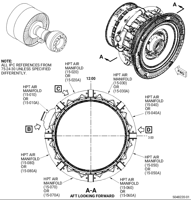
| (1) | Install the HPT air manifolds. Refer to Figure 1 of this Service Bulletin and to the GEnx-1B EM, 72-00-02, ASSEMBLY 004, CONFIG 01 or CONFIG 02 or GEnx-1B, Boeing 787 AMM, G75-24-05, Installation, DMC-B787-A-G75-24-05-00A-720A-A, to help with the installation and do as follows: |
| NOTE: |
|
| (a) | For pre-GEnx-1B S/B 75-0003 engines, do as follows: |
| 1 | Install the HPT air manifolds (15-030, 15-040, 15-050, 15-060, 15-070, 15-080, 15-010, and 15-020, 75-24-30, Figure 1, Sheet 1) as follows: |
| a | Install one of the new air bellows (4, Sheet 5) at the 12:00 o'clock position aft looking forward (ALF) on the HPT air manifold (15-030, Sheet 1). Push the air bellows (4, Sheet 5) fully onto the HPT air manifold (15-030, Sheet 1) tube and attach it firmly with a new hose clamp (3, Sheet 5). |
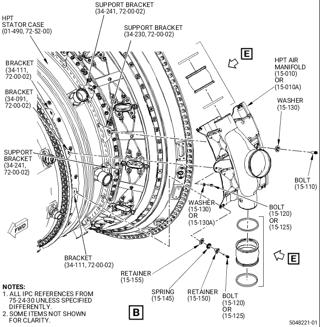
| b | Install the HPT air manifold (15-030, Sheet 1) at the 1:00 o'clock position ALF on the HPT stator case (01-490, 72-52-00, Sheet 2). |
| c | Attach the forward end of the HPT air manifold (15-030, Sheet 1) with one machine bolt (bolt) (15-120, 75-24-30, Sheet 2) and one retaining washer (washer) (15-130) at the center bolt hole. Hand-tighten the bolt (15-120). |
| d | Attach the aft end of the HPT air manifold (15-030, Sheet 1) with one bolt (15-110, Sheet 2) and one washer (15-130) at the center bolt hole. Hand-tighten the bolt (15-110). |
| e | Install the remaining HPT air manifolds on the HPT stator case (01-490, 72-52-00). Make sure that the HPT air manifold (15-010, 75-24-30) is installed at the 10:00 o'clock position ALF. |
| f | When all the HPT air manifolds are installed, carefully move the air bellows (4, Sheet 5) in a clockwise (CW) direction to connect the adjacent HPT air manifold. |
| g | Install the remaining bolts (15-120, Sheet 2) and washers (15-130) in the forward end of the HPT air manifolds. |
| h | Install the remaining bolts (15-110) and washers (15-130) in the aft end of the HPT air manifolds. |
| i | Torque the bolts (15-120 and 15-110) to 106 to 124 lb in. (11.9 to 14.0 Nm). |
| 2 | Torque the hose clamps (3, Figure 1, Sheet 5 and Sheet 6) as follows: |
| a | Torque the hose clamps (3) to 18 to 22 lb in. (2.0 to 2.4 Nm) and do as follows: |
| CAUTION: |
|
| (1) | Remove the excessive length of the hose clamp (3) tab to expose a maximum material length of 1.00 inch (25.4 mm) beyond the screw housing. No burrs are permitted. Refer to the SPM, 70-42-00, BLENDING AND REMOVAL OF HIGH METAL PROCEDURES. |
| WARNING: |
|
| b | Apply C01-007 silicone elastomer RTV on the screw and cylinder of the hose clamp (3) as follows: |
| (1) | Clean the surface with C04-002 solvent or C04-035 isopropyl alcohol. |
| (2) | Apply C01-007 silicone elastomer RTV on the screw of the hose clamp (3) to prevent further movement of the hose clamp (3) and air bellows (4). Make sure to only apply on the area of interest and not on the surrounding hardware. |
| (b) | For post-GEnx-1B S/B 75-0003 and all PIP 2 engines, do as follows: |
| 1 | Install one of the new air bellows (4, Figure 1, Sheet 5) on the CW end of the HPT air manifold (15-040A, Sheet 1). Push the air bellows (4, Sheet 5) fully onto the HPT air manifold (15-040A, Sheet 1) tube and attach it firmly with a new hose clamp (3, Sheet 5). |
| 2 | Install the HPT air manifold (15-040A, Sheet 1) on the HPT stator case (01-490, 72-52-00, Sheet 2) at the 2:00 o'clock position aft looking forward (ALF). |
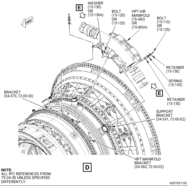
| 3 | Install one machine bolt (bolt) (15-120 or 15-125A, 75-24-30) and one flat washer (washer) (15-130 or 15-130A) at the forward center bolt hole and attach the HPT air manifold (15-040A, Sheet 1) to the HPT manifold bracket (bracket) (34-370, 72-00-02, Sheet 4). |
| 4 | Install the flat wire spring (spring) (15-145, 75-24-30, Sheet 4) between the retainers (15-150 and 15-155). |
| 5 | Install one bolt (15-125), retainers (15-150 and 15-155), and spring (15-145) at each forward corner bolt hole and attach the HPT air manifold (15-040A, Sheet 4) to the HPT manifold brackets (34-360, 72-00-02). |
| 6 | Install the remaining HPT air manifolds (15-030A, 15-050A, 15-060A, 15-070A, 15-080A, 15-010A, and 15-020A, 75-24-30, Sheet 1) as follows: |
| a | Install one of the new air bellows (4, Sheet 5) on the CW end of the HPT air manifold (15-050A, Sheet 1). Push the air bellows (4, Sheet 5) fully onto the HPT air manifold (15-050A, Sheet 1) tube and attach it firmly with a new hose clamp (3, Sheet 5). |
| b | Install the HPT air manifold (15-050A, Sheet 1) on the HPT stator case (01-490, 72-52-00, Sheet 2) at the 4:00 o'clock position ALF. |
| c | Install one bolt (15-125, 75-24-30) and one washer (15-130A) at the forward center bolt hole and attach the HPT air manifold (15-050A, Sheet 1) to the bracket (34-091, 72-00-02, Sheet 2). |
| d | Install the spring (15-145, 75-24-30) between the retainers (15-150 and 15-155). |
| e | Install one bolt (15-125), retainers (15-150 and 15-155), and spring (15-145) at each forward corner bolt hole and attach the HPT air manifold (15-050A, Sheet 1) to the brackets (34-111, 72-00-02, Sheet 2 and 34-360, 72-00-02, Sheet 4). |
| f | Install the remaining HPT air manifolds at their correct
positions. Do again steps 3.C.(1)(b)6 a through 3.C.(1)(b)6 d . |
| g | For the HPT air manifolds (15-060A, 15-070A, 15-080A, and 15-010A, 75-24-30, Sheet 1) installation, do as follows: |
| (1) | Install one bolt (15-125, Sheet 2), retainers (15-150 and 15-155), and spring (15-145) at each forward corner bolt hole and attach the HPT air manifolds (15-060A, 15-070A, 15-080A, and 15-010A, Sheet 1) to the brackets (34-111, 72-00-02, Sheet 2). |
| h | For the HPT air manifold (15-020A, 75-24-30, Sheet 1) installation, do as follows: |
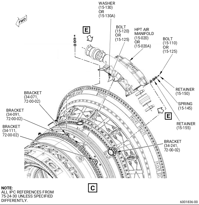
| (1) | Install one bolt (15-125, Sheet 2), retainers (15-150 and 15-155), and spring (15-145) at each forward corner bolt hole and attach the HPT air manifold (15-020A, Sheet 1) to the brackets (34-111 and 34-071, 72-00-02, Sheet 2 and Sheet 3). |
| i | For the HPT air manifold (15-030A, 75-24-30, Sheet 1) installation do as follows: |
| (1) | Install one bolt (15-125, Sheet 2), retainers (15-150 and 15-155), and spring (15-145) at each forward corner bolt hole and attach the HPT air manifold (15-030A, Sheet 1) to the brackets (34-360 and 34-071, 72-00-02, Sheet 3 and Sheet 4). |
| 7 | When all the HPT air manifolds are installed, carefully move the air bellows (4, Sheet 5) in a CW direction to connect the adjacent HPT air manifold. |
| 8 | Install the remaining spring (15-145, 75-24-30, Sheet 2) between the retainers (15-150 and 15-155). |
| 9 | Install one bolt (15-125), retainers (15-150 and 15-155), and spring (15-145) at the aft corner bolt holes on the HPT air manifolds and attach the HPT air manifolds to the support bracket (34-241, 72-00-02, Sheet 2 and Sheet 3). |
| 10 | Torque the bolts (15-125, 75-24-30) to 51 to 59 lb in. (5.7 to 6.6 Nm). |
| 11 | Torque the hose clamps (3, Figure 1, Sheet 5 and Sheet 6) as follows: |
| a | Torque the hose clamps (3) to 18 to 22 lb in. (2.0 to 2.4 Nm) and do as follows: |
| CAUTION: |
|
| (1) | Remove the excessive length of the hose clamp (3) tab to expose a maximum material length of 1.00 inch (25.4 mm) beyond the screw housing. No burrs are permitted. Refer to the SPM, 70-42-00, BLENDING AND REMOVAL OF HIGH METAL PROCEDURES. |
| WARNING: |
|
| b | Apply C01-007 silicone elastomer RTV on the screw and cylinder of the hose clamp (3) as follows: |
| (1) | Clean the surface with C04-002 solvent or C04-035 isopropyl alcohol. |
| (2) | Apply C01-007 silicone elastomer RTV on the screw of the hose clamp (3) to prevent further movement of the hose clamp (3) and air bellows (4). Make sure to only apply on the area of interest and not on the surrounding hardware. |