| COMMERCIAL ENGINE STANDARD PRACTICES MANUAL | Dated: 03/09/2017 | |
| SPM 70-11-01 SAFETY WIRE PROCEDURE | ||
| COMMERCIAL ENGINE STANDARD PRACTICES MANUAL | Dated: 03/09/2017 | |
| SPM 70-11-01 SAFETY WIRE PROCEDURE | ||
| TASK 70-11-01-400-005 |
| 1 . | General. |
| A. | Safety cable is permitted as an alternative to safety wire unless specifically prohibited by the assembly procedure. The three safety cable methods are equivalent alternatives and are interchangeable: |
| TASK 70-11-03-400-007, Safety Cable Method No. 1 (Bergen Tool), |
| TASK 70-11-04-400-008, Safety Cable Method No. 2 (Snap-On Tool), and |
| TASK 70-11-05-400-009, Safety Cable Method No. 3 (Daniels (DMC) Tool). |
| B. | Where possible, install stainless steel safety wire C10-071 by twisting two strands together (the double-twist method). One twist is defined as that produced by twisting the wires through an arc of 180 degrees and is equal to one-half a complete . The single strand method may only be used when specified. Allowable materials for use as safety wire are AMS 5685, 5687, 5689, and 5690. |
| CAUTION: |
|
| C. | Where possible, do not install safety wire in such a way as to cause the wire to be subjected to chafing, fatigue through vibration, or additional tension other than the tension imposed on the wire to prevent disengagement. |
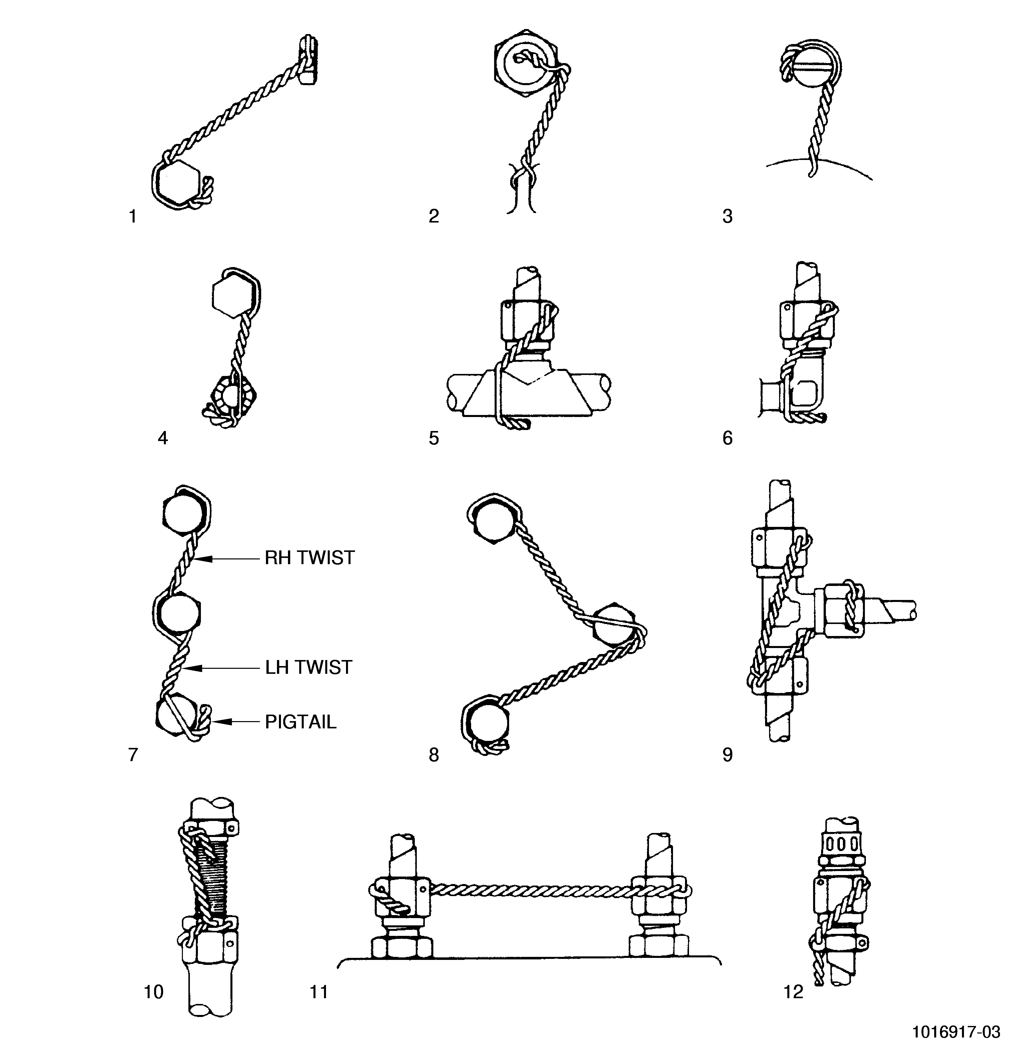
| D. | In all cases, safety wire must be installed through the holes provided. When no hole is provided, attach the wire to a neighboring part so as not to interfere with the function of the part, or surrounding parts, and in accordance with the recommendations of this section. See 5 and 6, Figure 1. |
| E. | The maximum span of safety wire between tension points shall be 6.0 inches (152.4 mm), unless otherwise specified. Where several fasteners form a group to be safety-wired together by either the single-strand or the double-twist method, the maximum number of units in a series shall be limited to the number of units that can be safety-wired by a 24.0 inch (609.6 mm) length of wire. When safety-wiring widely spaced units in a group, using the double-twist method, not more than three units must be safety-wired in a series. See 7 and 8, Figure 1. |
| CAUTION: |
|
| F. | Both 0.020 ± 0.001 inch (0.51 ± 0.03 mm) and 0.032 ± 0.001 inch (0.81 ± 0.03 mm) stainless steel safety wire are used throughout the engine. The choice is determined by the size of the hole in the unit to be safety-wired. When possible, use the 0.032 inch (0.81 mm) safety wire. |
| G. | Pull safety wire taut while twisting it. The twisted wire should have 9 to 12 twists per inch for 0.020 inch (0.51 mm) wire, and 7 to 10 twists per inch for 0.032 inch (0.81 mm) wire. |
| H. | Safety-wire hose and electrical coupling nuts in the same manner as the tube coupling nuts. See 5, 6, 9, 10, 11, and 12, Figure 1. |
| CAUTION: |
|
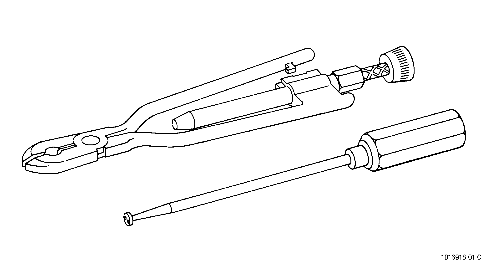
| I. | The use of commercially available safety wire twisting tools C10-150 is recommended. Two such tools are shown in Figure 2. |
| 2 . | Tools and Equipment. |
| Subtask 70-11-01-400-006 |
|
| 3 . | Consumables. |
| Subtask 70-11-01-400-062 |
|
| 4 . | Specific Techniques for Safety-wiring. |
| Subtask 70-11-01-400-063 |
| CAUTION: |
|
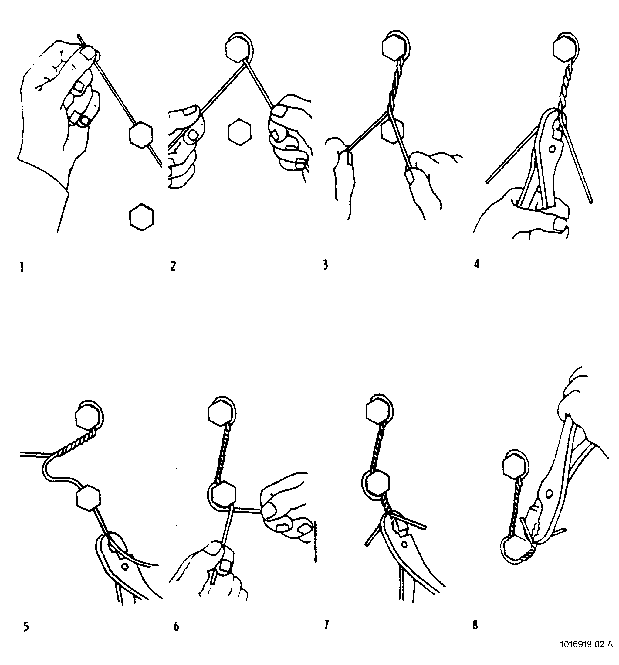
| A. | See Figure 3. Insert the safety wire through the first part, and bend the upper end either over the head of the part or around it. If bent around it, the direction of wrap and twist of the strands shall be such that the loop around the part comes under the strand protruding from the hole. Done this way, the loop will stay down and will not tend to slip up and leave a slack loop. See 1 and 2, Figure 3. |
| B. | Twist the strands while taut until the twisted part is just short of a hole in the next part. The twisted portion should be within 0.125 inch (3.18 mm) of the hole in the other part. See 3 and 4, Figure 3. |
| C. | If the free strand is to be bent around the head of the second part, insert the uppermost strand through the hole in this part, then repeat step A. If the free strand is to be bent over the unit, the direction of the twist is unimportant. If there are more than two units in the series, repeat the preceding steps. See 5 and 6, Figure 3. |
| D. | After safety-wiring the last part, continue twisting the wires to form a pigtail of three to six twists 0.250-0.50 inch (6.4-12.7 mm) long and cut off the excess wire. Bend the pigtail inwards toward the part to prevent it from becoming a snag. See 7 and 8, Figure 3. |
| NOTE: |
|
| E. | After safety-wiring, use the limits in Table 1 to determine its acceptability. If the length of the wire is between the distances given, use the flex limit for the shorter distance to approve or reject the installation. |
| NOTE: |
|
| F. | If safety wire fails to meet these limits, remove it and install new safety wire. |
| G. | Always cut rather than break safety wire so that safety wire holes are not torn or damage. |