| COMMERCIAL ENGINE STANDARD PRACTICES MANUAL | Dated: 10/01/2006 | |
| SPM 70-32-01 MAGNETIC-PARTICLE METHOD | ||
| COMMERCIAL ENGINE STANDARD PRACTICES MANUAL | Dated: 10/01/2006 | |
| SPM 70-32-01 MAGNETIC-PARTICLE METHOD | ||
| TASK 70-32-01-240-001 |
| 1 . | General. |
| WARNING: |
|
| A. | The magnetic-particle inspection process is a visual inspection aid used for detecting discontinuities open to the surface and those slightly below the surface in materials which are capable of being magnetized. |
| WARNING: |
|
| B. | Fluorescent ferromagnetic particles which are in suspension in a liquid are applied over the surface to be inspected and are attracted to the magnetic poles formed at a discontinuity during magnetization. An ultraviolet light is used to cause the particles to fluoresce, thereby making indications more visible. |
| C. | Personnel Requirements. |
| (1) | Personnel performing this inspection must be certified in accordance with the National Aerospace Standard 410 (NAS-410), American Society of Non Destructive Testing specification ASNT-TC-1A (ASNT-TC-1A), Air Transport Association Specification No. 105 (ATA 105), or a locally approved certification program. |
| (2) | Personnel performing this inspection should receive practical training in the use of this procedure and must demonstrate proficiency in use and control of the inspection equipment, inspection of hardware, and evaluation of indications before the authority to accept and reject hardware is delegated. |
| (3) | Any training which may be provided by General Electric for a technique requiring the performance of this inspection method does not imply that the personnel who receive that training have met the requirements for inspector certification in accordance with NAS-410, ASNT-TC-1A, or ATA 105. |
| 2 . | Theory. |
| Subtask 70-32-01-240-011 |
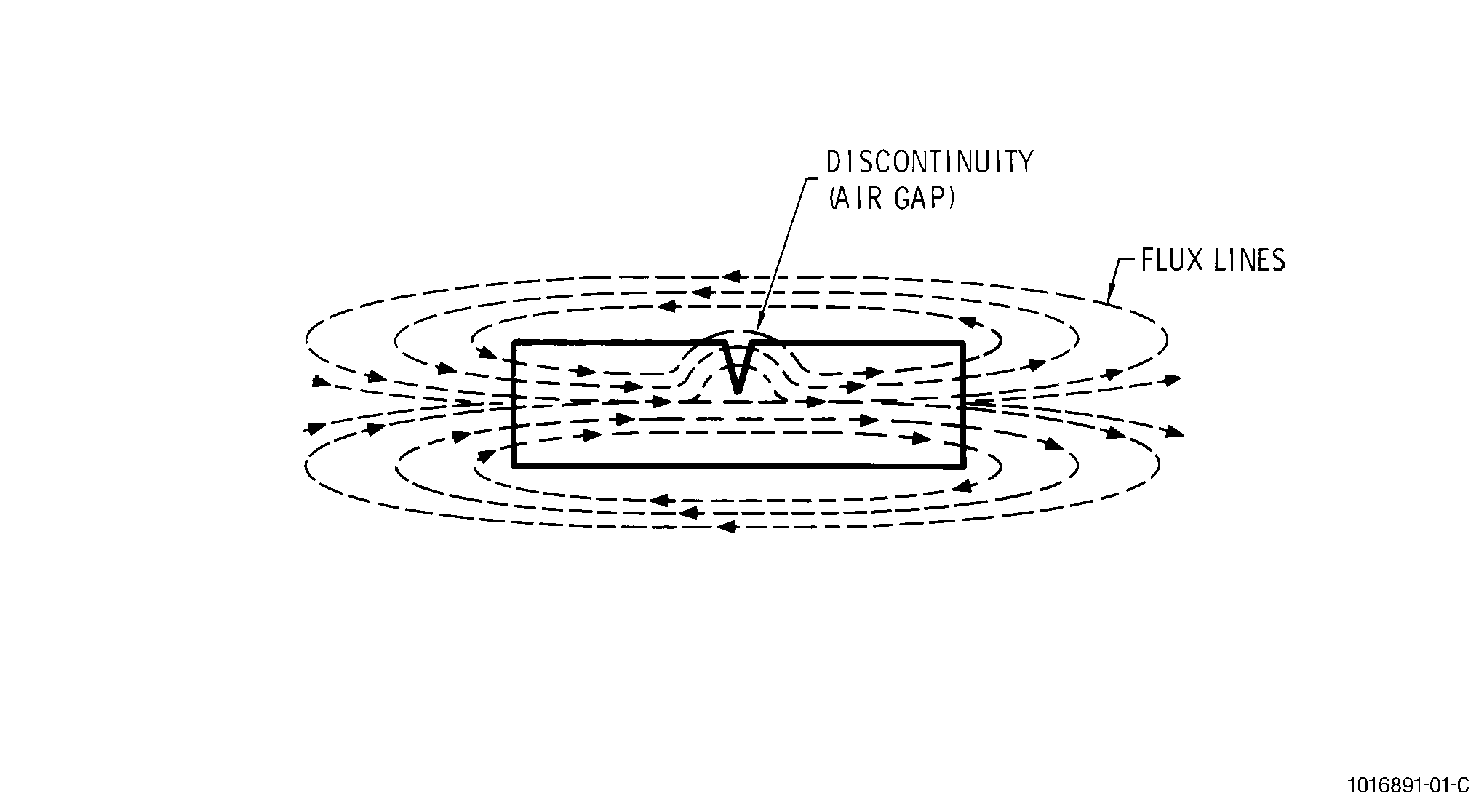
| A. | Magnetic-particle inspection basically consists of subjecting the parts to a magnetic field, which sets up magnetic lines of force in the part. Discontinuities cause the lines of force to be distorted and form new magnetic poles. Ferromagnetic particles, in suspension in a liquid flowing over the part, will be attracted to the new magnetic poles or discontinuities and adhere to the part as long as the magnetic force is maintained. |
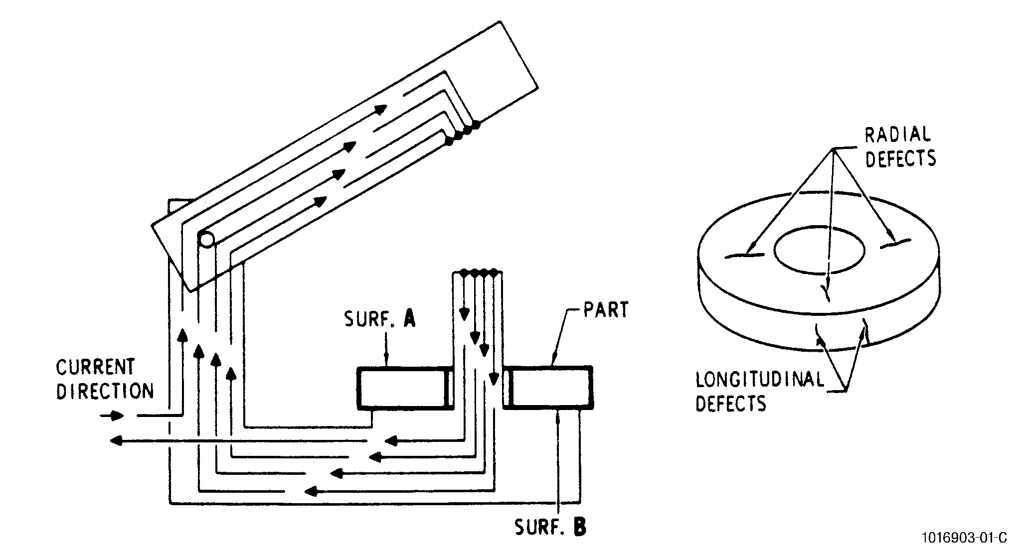
| B. | The direction and intensity of the magnetic field must be chosen to create strong magnetic leaks around the discontinuities, which act as an air gap. The defects are then made visible by the application of a liquid suspension of ferromagnetic particles to the surface of the part. See Figure 2. |
| C. | The ferromagnetic particles are coated with a material which fluoresces when subjected to ultraviolet light. The fluorescent particles effectively outline the discontinuity enabling the inspector to measure and evaluate the extent of the discontinuity. |
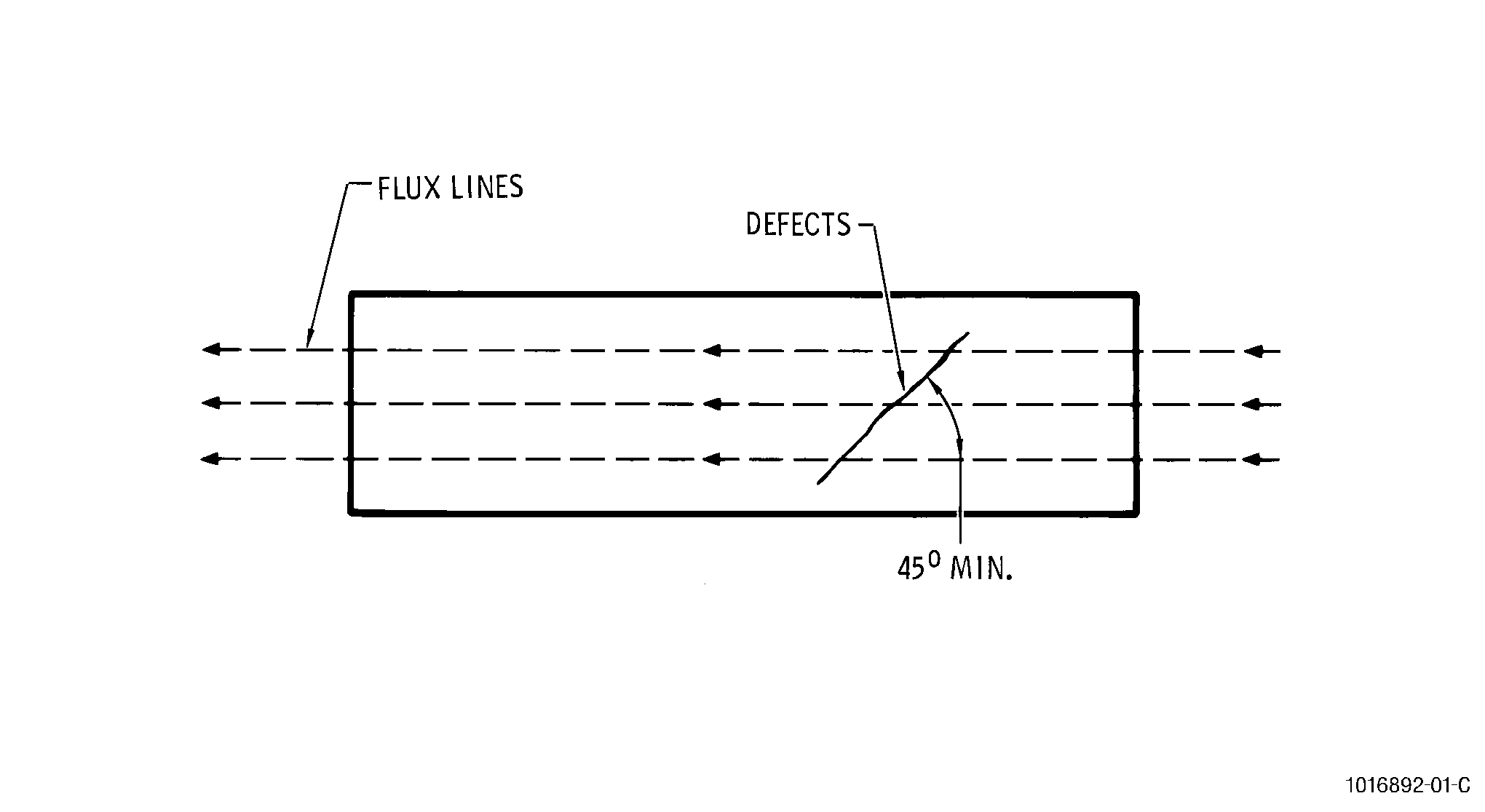
| D. | The detection of defects is most effective when their plane is perpendicular to the magnetic field. Detection remains possible as long as the angle between the defect and the field remains greater than 45 degrees. See Figure 1. |
| E. | Detection becomes increasingly difficult as the angle is reduced from 45 degrees and becomes impossible when the defect is in-line (zero degrees) with the magnetic force lines. It is, therefore, necessary to inspect the part using at least 2 directional fields, either by changing the position of the part relative to the field, or by using a different magnetization technique. The choice of technique to be used is determined by the shape and size of the part to be inspected. |
| 3 . | Preparation of Parts for Magnetic-Particle Inspection. |
| Subtask 70-32-01-240-012 |
| A. | Parts should be free of oil, dirt, or other surface contamination before inspection. |
| B. | If necessary, scratches or pitting due to contact corrosion may be removed by stoning. When the specified inspection method consists of passing the current through the part, the contact faces should be cleaned of any coating and polished to ensure good electrical conduction. It is not necessary to systematically remove protective coatings from parts purely for the magnetic-particle inspection. |
| C. | Prior to inspection, the part must be checked to assure the residual field strength is less than 240 A/m (3 oersted). If the maximum allowable field strength is exceeded, demagnetization is required per Subtask 70-32-01-240-014, Demagnetization. |
| 4 . | Magnetization Techniques. |
| Subtask 70-32-01-240-013 |
| A. | The techniques used to create the magnetic field vary according to the desired field direction relative to the part. |
| B. | These different techniques allow generation of: |
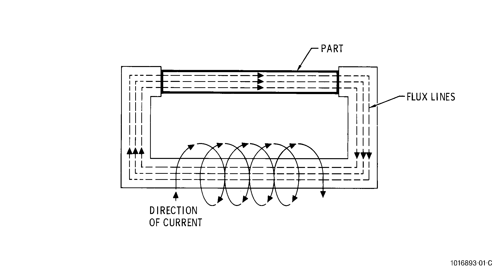
| (1) | Longitudinal fields, when the part to be inspected channels the lines of force. See Figure 4. |
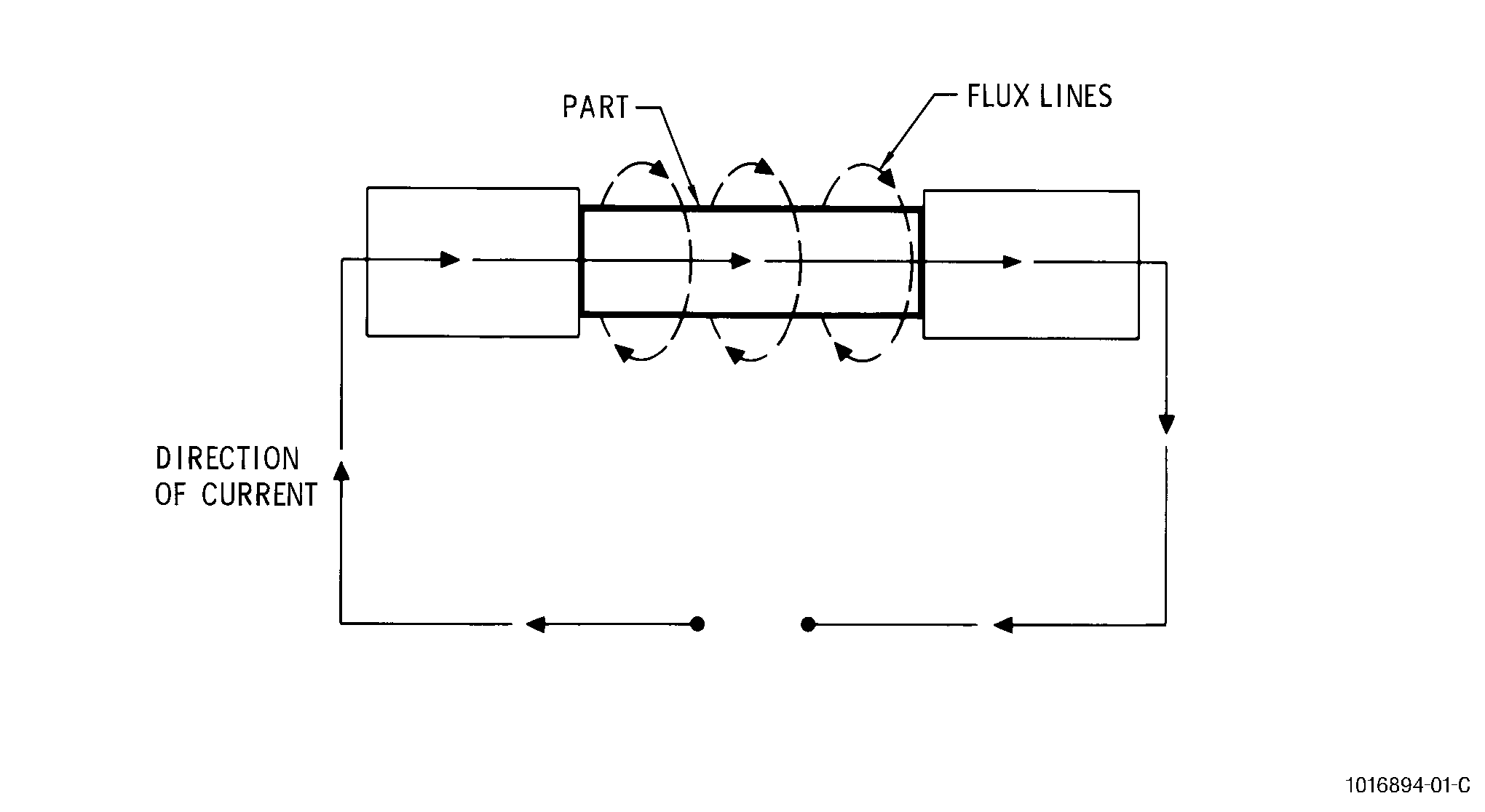
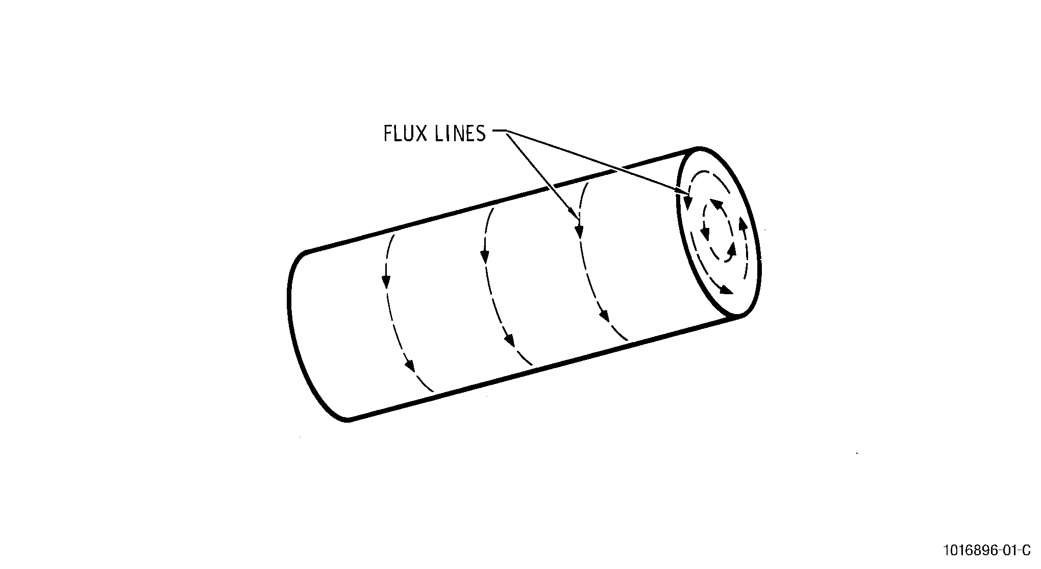
| (2) | Circular fields created by the passage of an electric current in the part (see Figure 3) according to the principle stated below. |
| C. | Basic Principle. |
| (1) | Any current flowing through a conductor creates a circular magnetic field, formed by closed loops, lying in a plane perpendicular to the conductor. A strong field exists as long as the current flows, and a residual field remains after the current is cut off. |
| 5 . | Demagnetization. |
| Subtask 70-32-01-240-014 |
| A. | Principle of Demagnetization. |
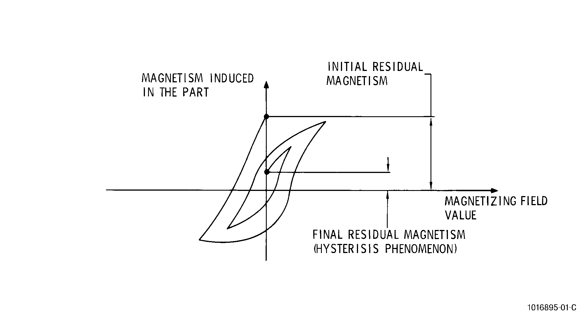
| (1) | Demagnetization is carried out by subjecting the part to magnetic fields of successively reversing polarity, and of rapidly decreasing strength. This result can be achieved either with the magnetization equipment or with supplementary apparatus. The phenomenon can be shown graphically. See Figure 6. |
| (2) | Due to the hysteresis effect, and the action of the Earth's magnetic field, demagnetization is never perfect from a theoretical viewpoint. For practical purposes, however, it is sufficient to demagnetize the parts to the limits imposed by the operating characteristics of the part, and of the equipment available to check the demagnetization. |
| B. | Using a Demagnetizer. |
| (1) | This method consists of subjecting the parts to an alternating magnetic field, formed inside a solenoid (demagnetizing tunnel). |
| (2) | Turn on the demagnetizer before introducing the parts. |
| (3) | Do not cut off the current while the parts are in, or close to, the demagnetizer. |
| (4) | Pass parts, which have a small diameter relative to the solenoid opening, close to a wall or in a corner of the solenoid opening. |
| (5) | Do not allow parts to remain stationary in the demagnetizer during operation in order to avoid the risk of heating the part. |
| C. | Demagnetization is Produced: |
| (1) | By gradually withdrawing the parts to approximately 4 feet (1.2 meters) from the demagnetizer, which effectively reduces the induced magnetism in the part. |
| (2) | By leaving the part in the solenoids, but reducing the current. |
| D. | Checking the Demagnetization. |
| (1) | The effectiveness of demagnetization must be checked by measuring the field strength. Unless otherwise indicated, a residual field of less than 240 A/m (3 oersted) is acceptable. |
| (2) | Checking for demagnetization is only possible if the part presents two distinct poles. If the part is cylindrical (without grooves, slots, etc.), the magnetic field is circular, therefore, it has no poles and the inspection will give no result. See Figure 5. Parts which are magnetized in this way (notably cylindrical parts), either by passage of a current or on a concentric central conductor, must be very carefully demagnetized, since no check is possible. |
| E. | Demagnetization Between Circular and Longitudinal. |
| All parts are magnetized in 2 directions, one circular and the other longitudinal relative to the geometry of the part. Demagnetization between these opposing fields is not required providing the circular magnetization is first and the longitudinal field strength is greater than the circumferential field. However, demagnetization after circumferential magnetization is usually accomplished for added insurance. |
| 6 . | Equipment Variables. |
| Subtask 70-32-01-240-015 |
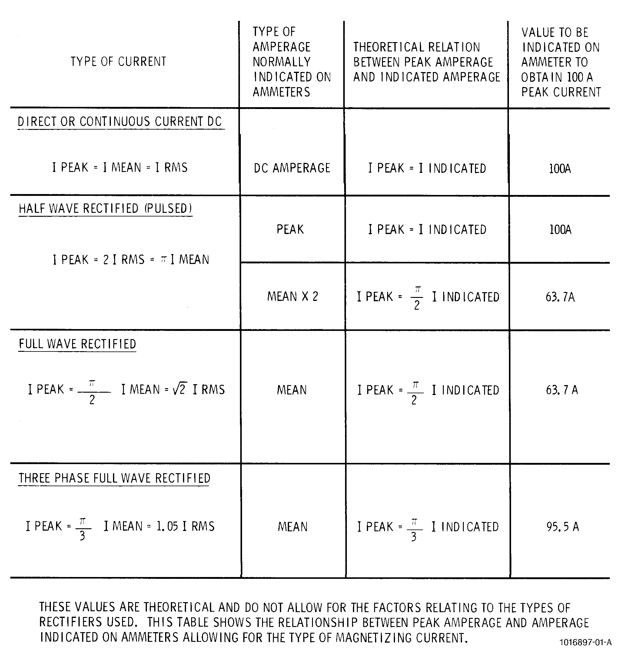
| A. | Several types of current are used (alternating, half- or full-wave rectified) as well as several types of magnetizing current indicators on the machine ammeters (effective or RMS current, mean current, etc.). The current values given in the manuals are peak values, and the user must correct the values given according to his type of equipment. The table in Figure 9 describes how these corrections are to be made. Current values should be maintained within ± 5 percent of the specified values. |
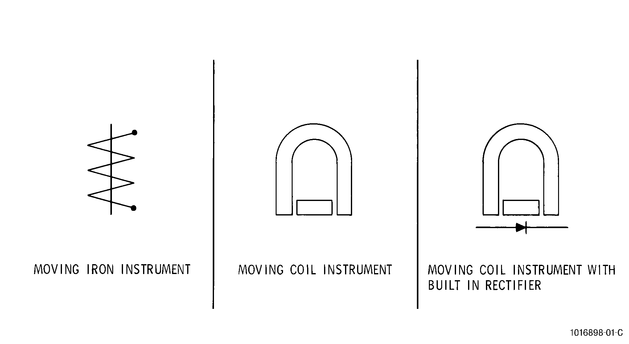
| B. | Checking the readings given by magnetic generator equipment. Having studied the tables given, it is necessary to know the type of magnetizing current, and the type of indication given by the ammeter on the machine. The type of magnetizing current may be determined by examining the circuit diagram of the machine, and can be confirmed with an oscilloscope. The type of current reading is indicated by symbols on the ammeter dial. See Figure 8. |
| (1) | The moving-iron instrument gives reading direct in RMS values. |
| (2) | The moving-coil meter gives mean currents. This type of instrument can only be used on direct or rectified current. |
| (3) | The moving-coil ammeter, with built-in rectifier indicates mean current values, whatever the type of magnetizing current. |
| (4) | It is essential to check the accuracy of these ammeters with a master ammeter. |
| (5) | Some magnetic inspection equipment is supplied by the manufacturer with the ammeter calibrated in peak values, twice mean value, etc. Take the corresponding change of scale, which must be clearly indicated on the instrument dial into account. |
| C. | Example of correction covered in Figure 9. |
| (1) | The magnetizing current is full-wave rectified, and the ammeter indicates mean current. For 100 A peak value, a current of 63.7 A must be indicated (refer to Figure 9). |
| (2) | If the value required in the manual is 1000 A, the inspector should read 637 A on his ammeter to fall within the correct inspection conditions. Refer to Figure 7 for typical inspection symbol. |
| D. | Example of correction not covered by the relationship table. See Figure 9. |
| (1) | The magnetizing current is half-wave rectified (pulsed), and the ammeter indicates mean current. For a pulsed current we have: |
| I Peak = I Mean (refer to the type of current column) |
| Therefore, for a 100 A peak value, the ammeter should show a mean current of: |
| I Mean = I Peak / pi = 100 / pi = 31.9 A |
| (2) | If the value required in the manual is 1000 A, the inspector should read 319 A on the ammeter. A typical inspection symbol is shown in Figure 7. |
| 7 . | Process Control. |
| Subtask 70-32-01-240-016 |
| A. | To control the quality of the magnetic-particle inspection processes, it is necessary to control the quality of the process, the materials, and the equipment. |
| B. | It is recommended that a quality assurance plan be established to check the process and materials on a regular schedule. |
| (1) | Process either the Known Defect Test Part (KDTP) or the Test Ring daily before any parts are processed. Reference TASK 70-32-80-700-010, Test of Magnetic-Particle Inspection Process. |
| (2) | The solution tests are recommended daily before any parts are processed. |
| (3) | Black ultraviolet light intensity checks are recommended weekly before any parts are processed or when ever a bulb or filter is changed in the lamp. Refer to TASK 70-32-80-700-010, Test of Magnetic-Particle Inspection Process. |
| (4) | Background white light in the inspection booth should be checked on a weekly basis. Refer to TASK 70-32-80-700-010, Test of Magnetic-Particle Inspection Process. |
| C. | It is also recommended that a quality assurance plan be developed to check the equipment on a regular basis as follows: |
| (1) | Use a calibrated ammeter to check the equipment ammeter at three points in the range through which the equipment is used. |
| NOTE: |
|
| (2) | On equipment that uses a timer to control current duration, check the timer to within ± 0.1 second with an electronic timer. |
| NOTE: |
|
| (3) | On equipment that uses a quick-break feature, use an oscilloscope or equipment recommended by the manufacturer to ensure the proper functioning of this feature. |
| NOTE: |
|
| (4) | Dead weight test yokes and permanent magnets every six months. |
| NOTE: |
|
| D. | If the process is not performed daily, and the process is determined to be out-of-control by the process test standard practice, all engine parts inspected since the last in-control point should be reprocessed. |
| 8 . | Symbols. |
| Subtask 70-32-01-240-017 |
| A. | There is a particular magnetic-particle inspection procedure for each part. To simplify these procedures, a system of symbols indicating the methods of inspection and the critical parameters has been established. Engine/Shop Manuals and process documents use these symbols to identify the recommended procedures. This standard practice defines the symbols and the procedures indicated by each symbol. |
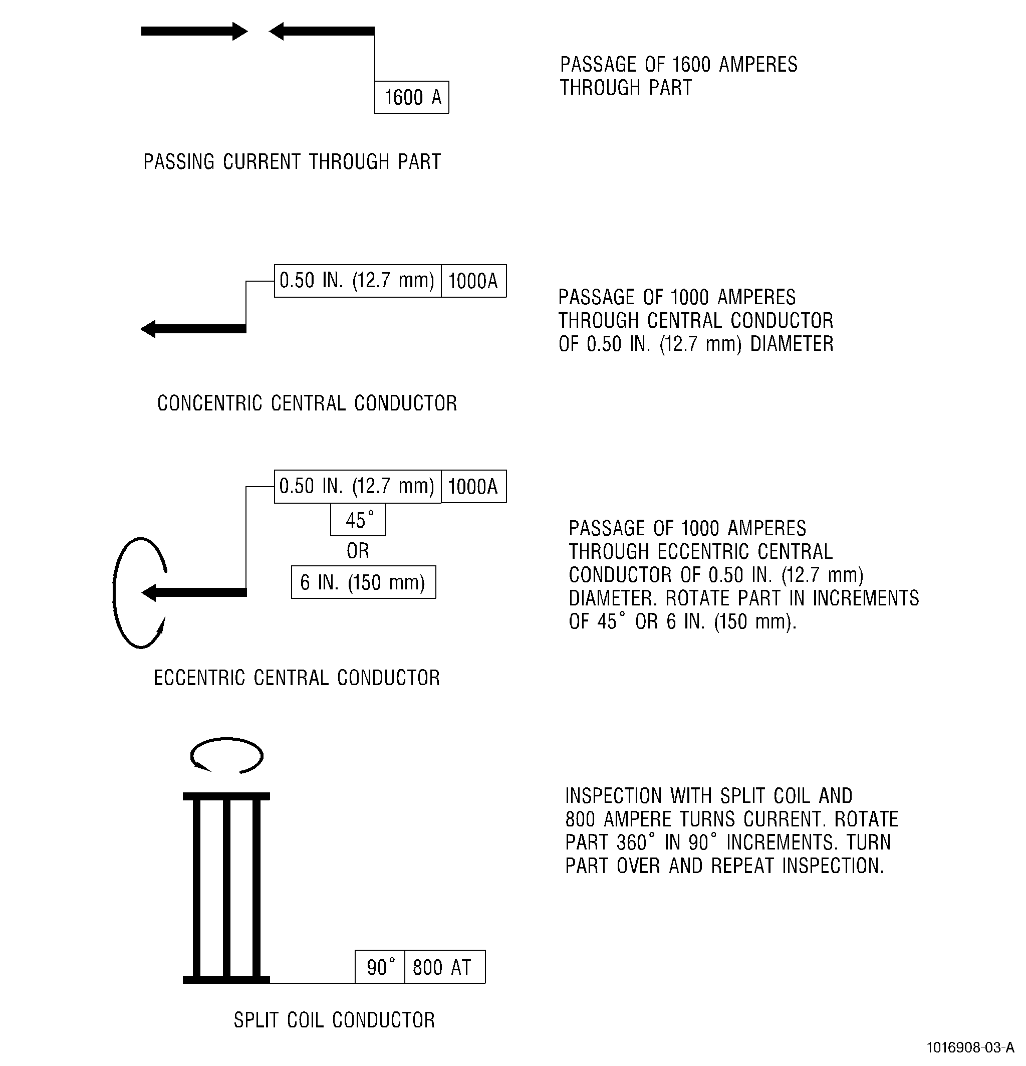
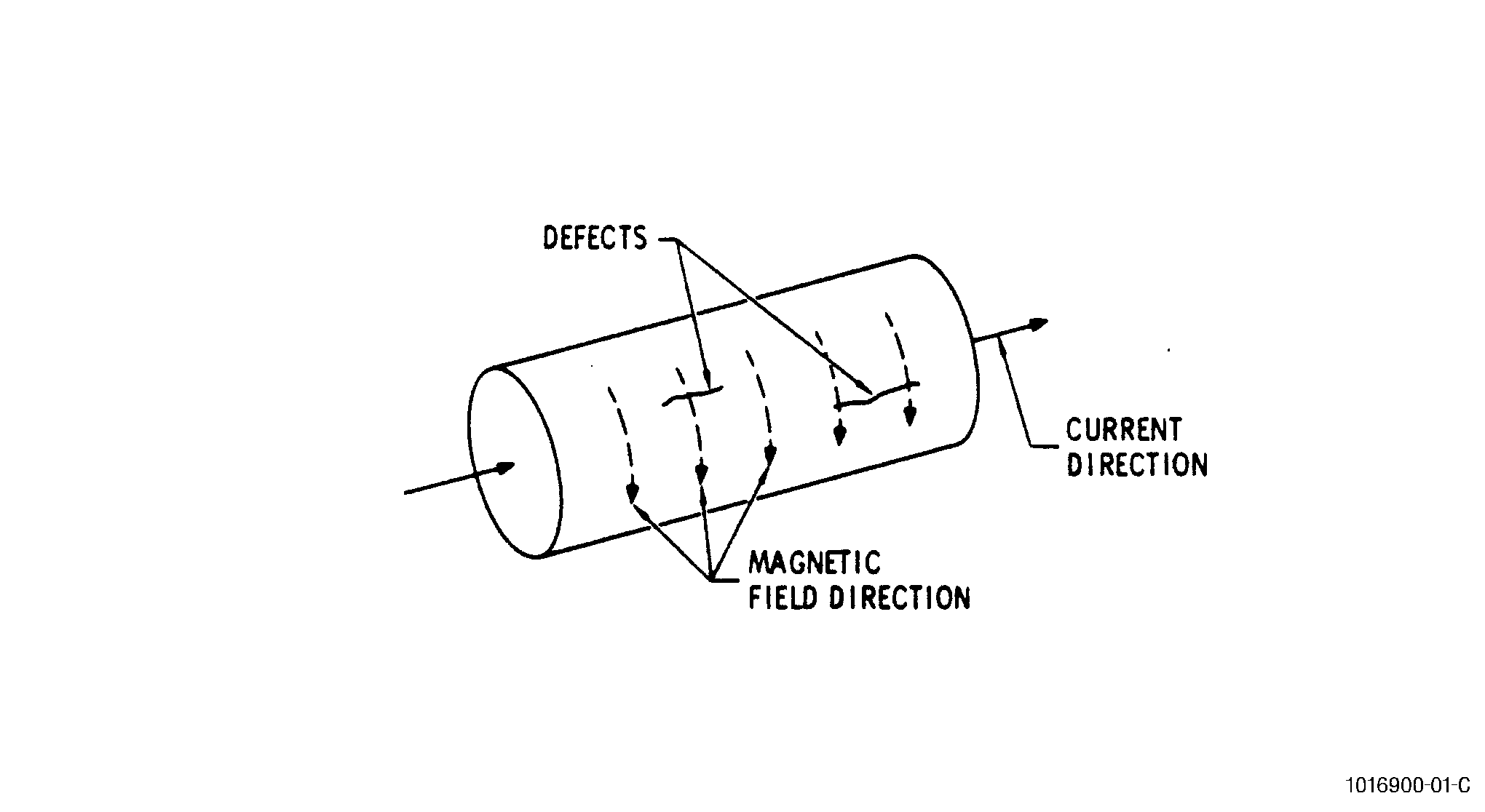
| B. | Passing Current Through the Part. See Figure 18. |
| (1) | Theory. |
| This procedure creates a circular magnetic field in the part, and allows longitudinal defects in the external surface to be detected. |
| (2) | Procedure. |
| WARNING: |
|
| CAUTION: |
|
| (a) | Check the condition of braided copper jaws (or possibly lead jaws) to ensure good contact between jaws and part. |
| (b) | Apply indicated current (1600 A), 2-3 pulses, for 0.5-1.0 second duration. |
| (c) | Stop flow of suspension solution before the last pulse. |
| (d) | Inspect part for defects. |
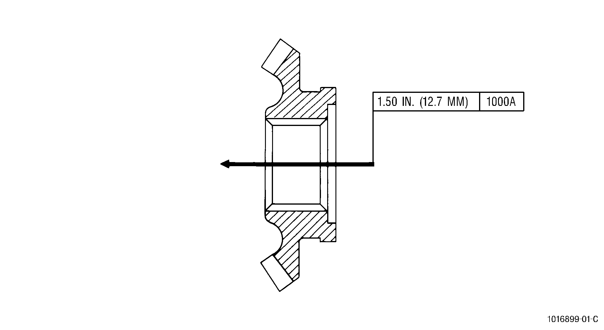
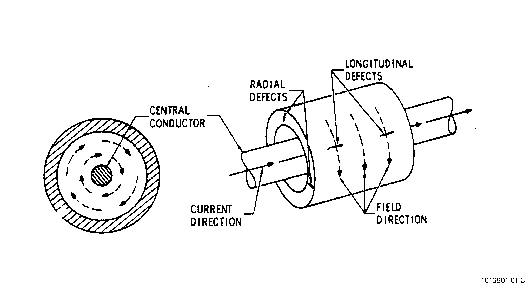
| C. | Using a Concentric Central Conductor. See Figure 17. |
| (1) | Theory. |
| This procedure creates a circular magnetic field in the part and allows detection of longitudinal defects in the internal and external surfaces, and radial defects in the end surfaces. |
| (2) | Procedure. |
| (a) | Position the part correctly, using a support of insulating material, if necessary, if the bar is horizontal. |
| (b) | Apply indicated current (1000 A), 2-3 pulses for 0.5-2.0 seconds duration through the central conductor bar. |
| (c) | Stop flow of suspension solution before the last pulse. |
| (d) | Inspect part for defects. |
| D. | Using an Eccentric Central Conductor. See Figure 16. |
| (1) | Theory. |
| (a) | This procedure creates a circular magnetic field in the part and allows detection of longitudinal defects on internal and external surfaces, and radial defects on end surfaces. |
| (2) | Procedure. |
| CAUTION: |
|
| (a) | Apply indicated current (1000 A), one pulse for 0.5-2.0 seconds duration, at each position of the part with the suspension solution flowing continuously. |
| (b) | Rotate the part to reposition at 45 degrees or 6 inches (150 mm) of peripheral length for each pulse of current. |
| (c) | After complete rotation with suspension solution flowing, repeat magnetizing at all positions with no flow of suspension solution. |
| (d) | Inspect part after total magnetization of the part by complete rotation. |
| (e) | Inspect large parts, requiring more than eight positions to complete the rotation, after each magnetization: one pulse with suspension solution flowing followed by one without. |
| E. | Using a Split Coil Conductor (Knife Switch). See Figure 15. |
| (1) | Theory. |
| This procedure creates a circular magnetic field in the part and permits detection of radial defects on the face of the part, and longitudinal defects on the outer surfaces. |
| (2) | Procedure. |
| (a) | Fixed table method. |
| 1 | Determine current by dividing the ampere-turns (AT) by the number of turns in the coil being used. |
| 2 | Apply current, 2-3 pulses, for 0.5-2.0 seconds duration, with "quick break" current decay at each position of part. |
| 3 | Stop flow of suspension solution before the last pulse. |
| 4 | Restrict the flow of suspension solution to the quadrant being magnetized at each position. |
| 5 | Inspect part after complete rotation and magnetization (four positions). |
| 6 | Repeat procedure if part is to be turned over as indicated by symbol. See Figure 14. |
| (b) | Rotating table method. |
| 1 | Determine current by dividing the ampere-turns (AT) by the number of turns in the coil being used. |
| 2 | Apply current, one pulse of 2-4 seconds duration, with "quick break" current decay while slowly rotating the part with suspension solution flowing. |
| 3 | Apply as many pulses, as needed, for 360 degrees rotation with current on. Stop flow of suspension solution and repeat magnetization. |
| 4 | Inspect part after complete rotation and magnetization of part. |
| 5 | Repeat procedure if part is to be turned over as indicated by symbol. See Figure 14 through Figure 20. |
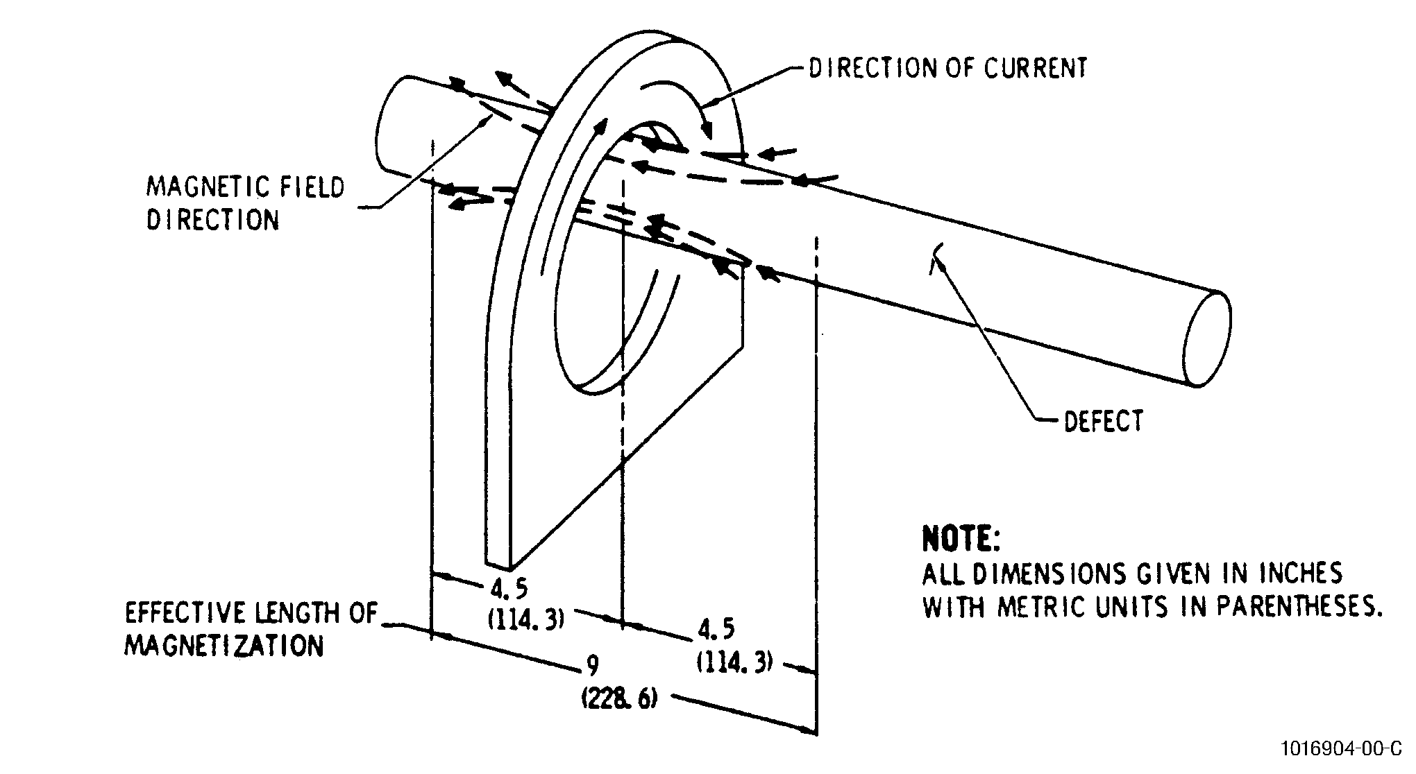
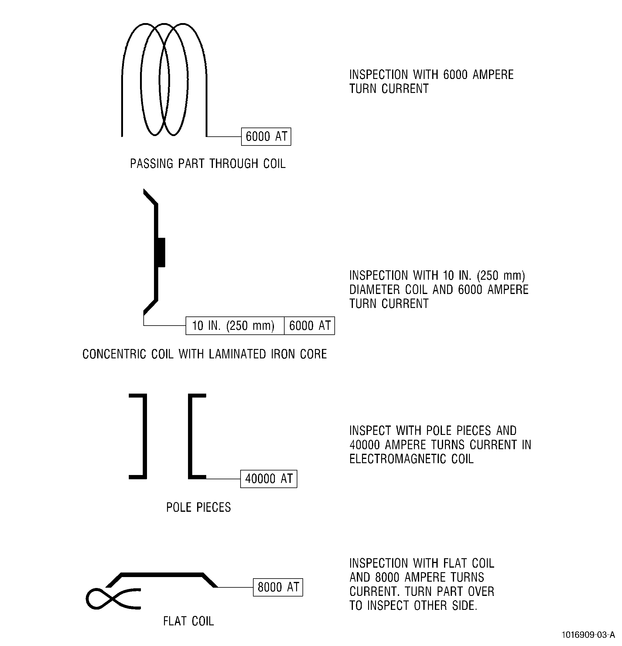
| F. | Using a Coil into Which Part is Positioned. See Figure 13. |
| (1) | Theory. |
| (a) | This procedure creates a longitudinal magnetic field in the part and permits detection of circumferential defects. |
| (b) | This procedure is used for long circular parts and for parts where access is difficult. |
| (c) | A magnetic field is induced into the part when the part is placed into the current carrying coil. |
| (d) | The long axis is pointed through the opening of the coil and the part is held near the inside edge of the coil. |
| (e) | This procedure is used on parts which have a length to diameter ratio of one or more. |
| (f) | The magnetic field is effective approximately 4-5 inches (100-125 mm) on each side of the centerline of the coil. On long parts, magnetization must be carried out in several stages. Each stage is carried out on the section of the part which is inside the coil where the magnetic field is properly distributed. |
| (2) | Procedure. |
| (a) | Determine current by dividing the ampere-turns (AT) by the number of turns in the coil being used. |
| (b) | Apply current, 2-3 pulses for 0.5-2.0 seconds duration, with "quick break" current decay at each position of the part. |
| (c) | Stop the flow of suspension solution before the last pulse. |
| (d) | Inspect after complete magnetization of the part. |
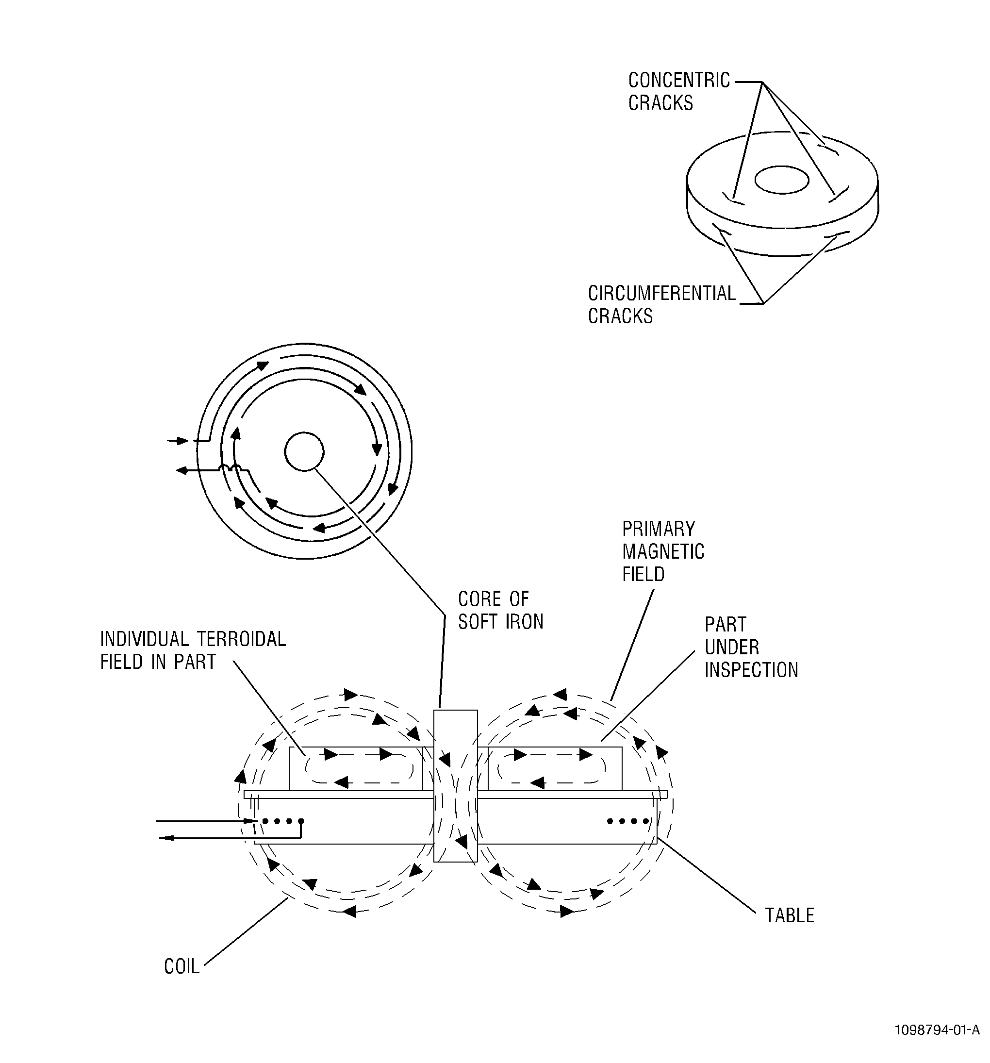
| G. | Using Induced Current Technique. See Figure 12. |
| (1) | Theory. |
| (a) | This procedure induces a toroidal magnetic field in the part and allows detection of circumferential defects. |
| (b) | This procedure is used for hollow parts with small length to diameter ratios. |
| (c) | The part is placed inside and concentric with the coil. The axis of the part is parallel to that of the coil. A soft iron laminated core is placed inside and concentric with the part. |
| (d) | The rapid collapse of current in the coil induces circulating eddy currents in the part. This, in turn, induces a toroidal magnetic field in the part. |
| (2) | Procedure. |
| (a) | Determine current by dividing the ampere-turns (AT) by the number of turns in the coil being used. |
| (b) | Apply current, 2-3 pulses for 0.5-1.0 second duration, with "quick break" current decay. |
| (c) | Stop the flow of suspension solution before the last pulse. |
| (d) | Inspect the part for defects. |
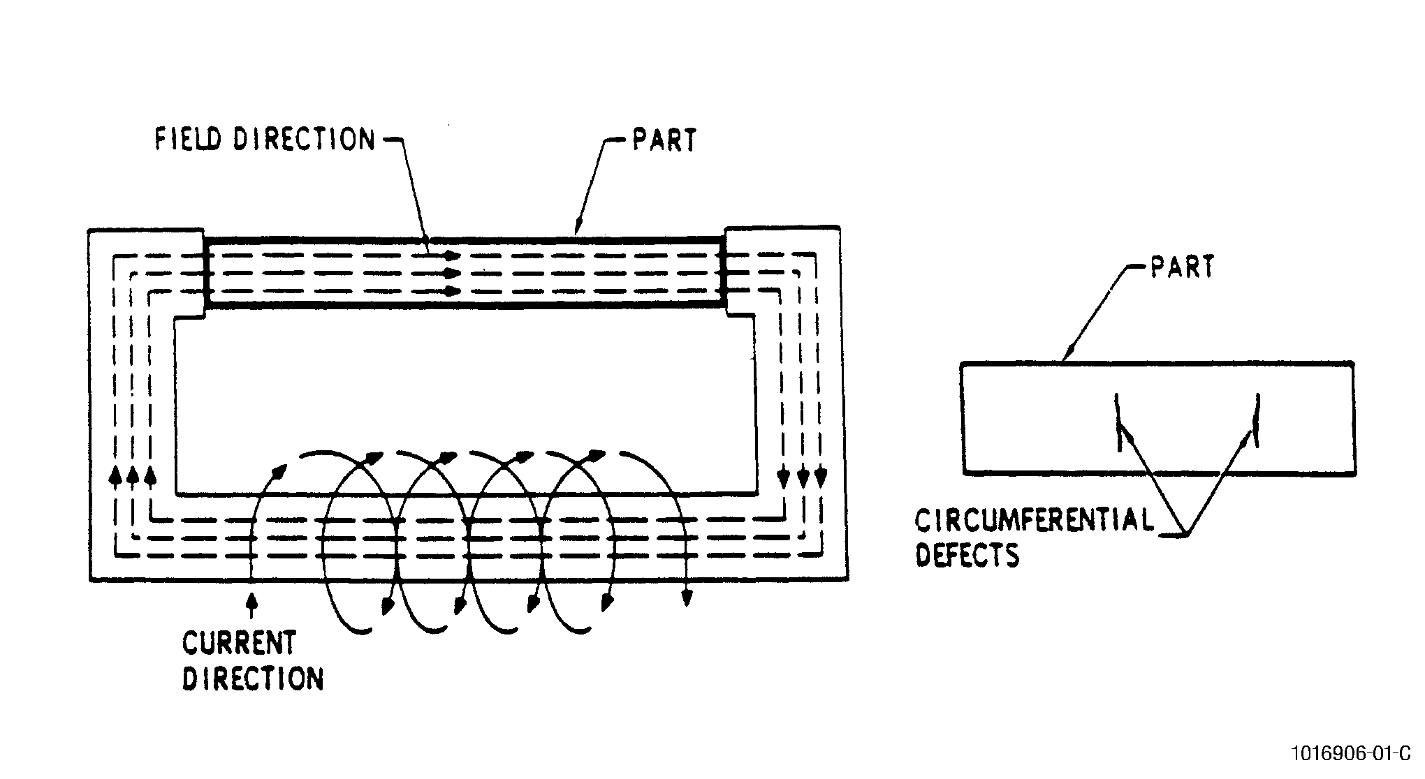
| H. | Using Pole Pieces. See Figure 11. |
| (1) | Theory. |
| (a) | This procedure induces a longitudinal magnetic field in the part, and permits detection of circumferential defects. |
| (b) | The part being inspected is held between the pole pieces of the electromagnetic machine. The part completes the magnetic circuit and channels the lines of force. |
| (c) | On occasion, an accumulation of excess magnetic-particle forms at the end of the parts which are in contact with the pole pieces. These areas can be subsequently inspected using the residual magnetism. |
| (2) | Procedure. |
| (a) | Determine current by dividing the ampere-turns (AT) by the number of turns in the coil being used. |
| (b) | Apply current, 2-3 pulses for 0.5-2.0 seconds duration. |
| (c) | Stop the flow of suspension solution before the last pulse. |
| NOTE: |
|
| (d) | Inspect part for defects. |
| I. | Using a Flat Coil. See Figure 10. |
| (1) | Theory. |
| (a) | This procedure is used to detect circumferential defects. It is particularly suitable for short parts having large cross sections. The maximum diameter of a part must not exceed the diameter of the coil. |
| (b) | The coil uses a spirally rolled cable and a soft iron core. The part being inspected is positioned on the coil. |
| (c) | When a continuous current flows, a magnetic field is generated. The intensity of this field is strengthened, in part, by a current induced when the secondary circuit is interrupted with "quick break" current decay. |
| (d) | The face on which the part rests must be turned up and inspected upon completion of inspection of other face. |
| (e) | This procedure creates a toroidal field in the part, allowing detection of circumferential defects. |
| (2) | Procedure. |
| (a) | Determine the current by dividing the ampere-turns (AT) by the number of turns in coil being used. |
| (b) | Apply current, 2-3 pulses for 0.5-2.0 seconds duration with "quick break" current decay. |
| (c) | Stop the flow of suspension solution before the last pulse. |
| (d) | Inspect part for defects. |
| (e) | Turn the part over and repeat magnetization and inspection of other side as indicated by symbol. |
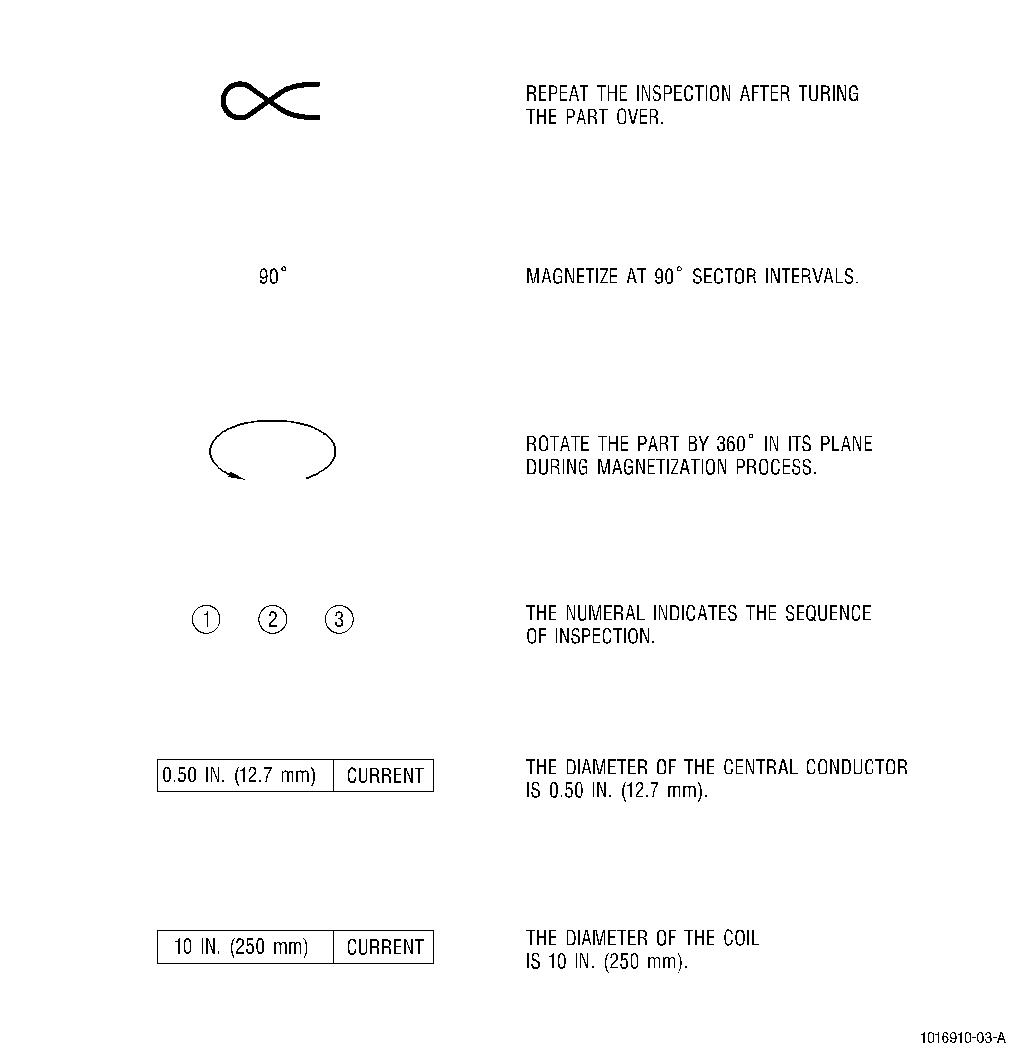
| J. | Additional Symbols. See Figure 14. |
| These additional symbols are used in conjunction with the process symbols and have the shown meanings. |
| 9 . | Inspection. |
| Subtask 70-32-01-240-018 |
| A. | General. |
| (1) | Fluorescent-penetrant inspection shall always precede magnetic-particle inspection if both inspections are required. |
| (2) | Each part must be magnetized in 2 directions to locate all defects. Circular magnetization and inspection must always precede longitudinal magnetization and inspection. |
| (3) | Parts on which a coating is to be replaced because of deterioration (peeling, flaking, cracking, etc.) should not be inspected until after the coating is removed. Normally, protective coatings less than 0.004 inch (0.10 mm) thick are not removed from parts for inspection purposes. However, coatings which do not allow the suspension solution to wet the part surface must be removed to achieve a reliable inspection. The process document will specify when coatings must be removed. |
| (4) | The specified values of current for each part are based on 3-phase, full-wave, rectified current. If the equipment in use has a different power supply, adjustments to these current values may be necessary. The specified values of current are based upon the equipment specified in the equipment list. If such equipment is not used, equivalent magnetization can be verified by using a gauss meter capable of determining the peak values of the tangential field using a Hall-effect probe. The tangential applied field strength levels shall be in the range of 30-60 gauss (2.4-4.8 kAm1) and shall be present in all areas of the part to be inspected. |
| B. | Equipment. |
| (1) | Magnetic-particle inspection equipment rated 6000 amp, 3-phase, full-wave rectified, alternating current with "quick break" current decay such as: |
| NOTE: |
|
| (a) | Magnaflux ARQ 966: Magnaflux Corporation. Refer to the List of Suppliers in Step 4 of 70-80-00. |
| (b) | SREM 6022R: SREM. Refer to the List of Suppliers in Step 4 of 70-80-00. |
| (c) | For pole piece inspection, use two coils mounted in parallel 1122 turns per coil, 22 amp rating. |
| (d) | For vertical coil inspection, use one coil, 5 turns, 14 inches (360 mm) diameter, 2700 amp rating. |
| (e) | Split coil conductor, use SREM 6000 with rotating table, 4 turn coil, 24 inches (600 mm) diameter, 6000 amp rating. |
| (f) | Flat coil, use SREM, 9 turns, 2700 amp rating. |
| (g) | Various diameter coils: |
| 1 | Magnaflux, P/N 74610, 2 inches (50 mm) diameter, 6 turns. |
| 2 | Magnaflux, P/N 74615, 4 inches (100 mm) diameter, 5 turns. |
| 3 | Magnaflux, P/N 74620, 6 inches (150 mm) diameter, 8 turns. |
| 4 | Magnaflux, P/N 74630, 10 inches (250 mm) diameter, 12 turns. |
| 5 | Magnaflux, P/N 74635, 12 inches (305 mm) diameter, 12 turns. |
| (h) | Demagnetization equipment using alternating current. |
| (i) | Demagnetization equipment using reversing DC coil with a 30-point step-down current decay. |
| (2) | Auxiliary equipment. |
| (a) | Assortment of non-magnetic central conductors such as brass or copper in different diameters ranging from 0.25 inch to 2 inches (6 to 50 mm) and 18 inches (460 mm) in length. |
| (b) | Laminated soft iron cores. |
| (c) | Flexible electrical cables. |
| (d) | Shunt test meter. |
| (e) | Black light borescope. |
| (f) | "Quick break" test instrument such as Magnaflux Corporation, P/N 148335, or equivalent. |
| (g) | Inspection booth or darkroom which prevents excessive admission of white light. |
| (h) | White light lamp for visual inspection of parts. |
| (i) | Assortment of adjustable mirrors. |
| (j) | Black light to detect fluorescent indications. |
| C. | Materials. |
| NOTE: |
|
|
| WARNING: |
|
| D. | Procedure. |
| NOTE: |
|
| NOTE: |
|
| NOTE: |
|
| NOTE: |
|
| (1) | Magnetization of parts. |
| NOTE: |
|
| (a) | Position part and equipment according to the recommended procedure specified in the process document. |
| (b) | Apply magnetic-particle suspension solution to part (wet continuous method). |
| (c) | Magnetize part for specified time and current. |
| (d) | Discontinue suspension solution flow immediately preceding last current pulse. |
| (2) | Inspection of parts. |
| (a) | Allow suspension solution to remain on part for 1 minute before inspection. |
| (b) | Inspect part, to limits specified in process document, in a darkened room under ultraviolet light. |
| (c) | Inspect all areas of part. Inside surfaces such as shafts or holes may require use of a mirror or borescope. |
| (d) | Verify all indications. |
| 1 | False indications. |
| An accumulation of magnetic particles not held magnetically, but present due to: |
| a | Foreign substance adhering to part. |
| b | Foreign fluorescent substance adhering to part. |
| c | Suspension drainage flowpaths. |
| d | Handling, fixture, or equipment smudges. |
| e | Foreign particles such as lint fibers in suspension solution. |
| NOTE: |
|
| 2 | Irrelevant indications. |
| These are true indications caused by magnetic leakage fields, and are generally acceptable. Some examples are: |
| a | Scratches, dents, and burrs. |
| b | Machine tool marks. |
| c | Brazed joint. |
| d | Sharp fillets. |
| e | Dissimilar permeabilities. |
| f | Heat treat scale. |
| NOTE: |
|
| 3 | Relevant or true indications. |
| Actual magnetic leakage fields judged acceptable or rejectionable per specified allowable limits. Some examples are: |
| a | Cracks. |
| b | Stringers. |
| c | Inclusions. |
| d | Laps/folds. |
| e | Lack of weld fusion/penetration. |
| f | Seams. |
| NOTE: |
|
| (e) | Identify relevant defect indications and record required information. Mark or tag parts as necessary. |
| (3) | Demagnetization of parts. |
| (a) | Various methods of demagnetization may be used depending upon equipment and/or size and shape of part. |
| (b) | Demagnetize as follows: |
| 1 | Pass parts through entire length of demagnetizer coil with current on. |
| 2 | Parts should be held close to top or sides of coil. |
| 3 | Rotate circular parts while withdrawing from coil. |
| 4 | Withdraw parts in a straight line from coil, and do not turn off power until part is 4 feet (1.2 meters) from coil. |
| NOTE: |
|
| (4) | Test for demagnetization. |
| (a) | Place probe of magnetic field test instrument in contact with part. |
| (b) | Move probe over all areas of parts, especially top and bottom rims of flanges, and all projections from main body. |
| (c) | Observe indicator. It should not deflect more than 3 oersteds from its point of reference. |
| (5) | Cleaning. |
| (a) | Clean part with petroleum solvent C04-002 . |
| (b) | Coat part with corrosion protective oil C02-025 , as required. |
| (6) | Quality assurance. |
| (a) | Check part with magnetic field indicator to assure magnetic field is 3 oersteds or less. |
| (b) | Inspect part under ultraviolet lamp to assure all fluorescent material has been removed. |
| (c) | Make sure the following process and material tests have been met. |
| 1 | Process Test TASK 70-32-80-700-010, Test of Magnetic-Particle Inspection Process. |
| 2 | Magnetic-Particle Suspension Solution Test per Solution Sheet S1041. |