| COMMERCIAL ENGINE STANDARD PRACTICES MANUAL | Dated: 05/13/2022 | |
| SPM 70-32-07 HIGH SPEED AND SLOW SPEED EDDY CURRENT INSPECTION OF CIRCULAR HOLES IN INCONEL OR TITANIUM ENGINE PARTS | ||
| COMMERCIAL ENGINE STANDARD PRACTICES MANUAL | Dated: 05/13/2022 | |
| SPM 70-32-07 HIGH SPEED AND SLOW SPEED EDDY CURRENT INSPECTION OF CIRCULAR HOLES IN INCONEL OR TITANIUM ENGINE PARTS | ||
| TASK 70-32-07-250-001 |
| 1 . | General. |
| NOTE: |
|
| A. | This practice describes the equipment and processes used for eddy current inspection of circular holes in engine parts. These techniques are used to detect flaws or discontinuities at, or near, the surface of metallic parts which may be detrimental to the part life or limit its intended use. |
| B. | Only qualified operators specifically designated, trained and approved to perform a specified inspection shall perform that test. Operators must be capable of performing equipment calibrations, carrying out the intended inspection and be capable of acceptable interpretation of output test data before his acceptance or rejection of hardware in accordance with an inspection procedure. |
| C. | There are three inspection methods: |
| Method A (High Speed) is in Subtask 70-32-07-250-011, High Speed Eddy Current Inspection (Method A). |
| Method B (Slow Speed) is in Subtask 70-32-07-250-012, Slow Speed Eddy Current Inspection (Method B). |
| Method C (High Speed with Electronic Data Acquisition) is in Subtask 70-32-07-250-013, High Speed Eddy Current Inspection with Electronic Data Acquisition and Storage (Method C). |
| 2 . | High Speed Eddy Current Inspection (Method A). |
| Subtask 70-32-07-250-011 |
| A. | Method A: High Speed Eddy Current Inspection. |
| (1) | Scope. |
| (a) | This document describes the equipment, technique and procedure necessary to do a 2 MHz high speed eddy current inspections of circular holes in aircraft engines hardware for the detection of cracking. A Service Bulletin or Engine/Shop Manual procedure is required for the detailed information needed for inspection of specific parts. |
| (b) | This document describes the general procedure and equipment which have been approved for the performance of high speed eddy current hole inspections. Exceptions to this procedure may be required for specific cases where the procedure or equipment described in this procedure cannot be used or is not appropriate. Such exceptions should be obtained in writing from GE Aircraft Engines. |
| (2) | Applicable Documents. |
| (a) | Instruction manuals or other information provided by equipment manufacturers. |
| (b) | The appropriate Service Bulletin or Engine/Shop Manual inspection for the hardware inspection. |
| (c) | Kit preparation and quality assurance plan, M & FQT Procedure 1480 (applies to GEAE/QTC only). |
| (3) | Personnel Requirements. |
| (a) | Personnel performing this inspection shall be certified in accordance with one of the following: |
| 1 | National Aerospace Standard 410 (NAS 410), which replaces MIL-STD 410 |
| 2 | American Society of Nondestructive Testing specification ASNT-TC-1A (ASNT-TC-1A) |
| 3 | Air Transport Association Specification No. 105 (ATA 105) |
| 4 | Comite Sectoriel Aeronautique Cofrend (COSAC) |
| 5 | A locally approved certification program. |
| (b) | Personnel performing this inspection should receive practical training in the use of this procedure and must demonstrate proficiency in calibration of the inspection equipment, inspection of hardware, and evaluation of indications before the authority to accept and reject hardware is delegated. |
| (c) | Any training which may be provided regarding the performance of this inspection does not imply that the personnel who receive that training have met the requirements for inspector certification in accordance with paragraph (3)(a).. |
| (4) | Equipment Requirements. |
| NOTE: |
|
| NOTE: |
|
| NOTE: |
|
| (a) | The eddy current instruments listed in Table 1 are approved for use with this procedure. |
| NOTE: |
|
| NOTE: |
|
| NOTE: |
|
| (b) | Probe rotors, associated cables, and adapters are listed in Table 2. |
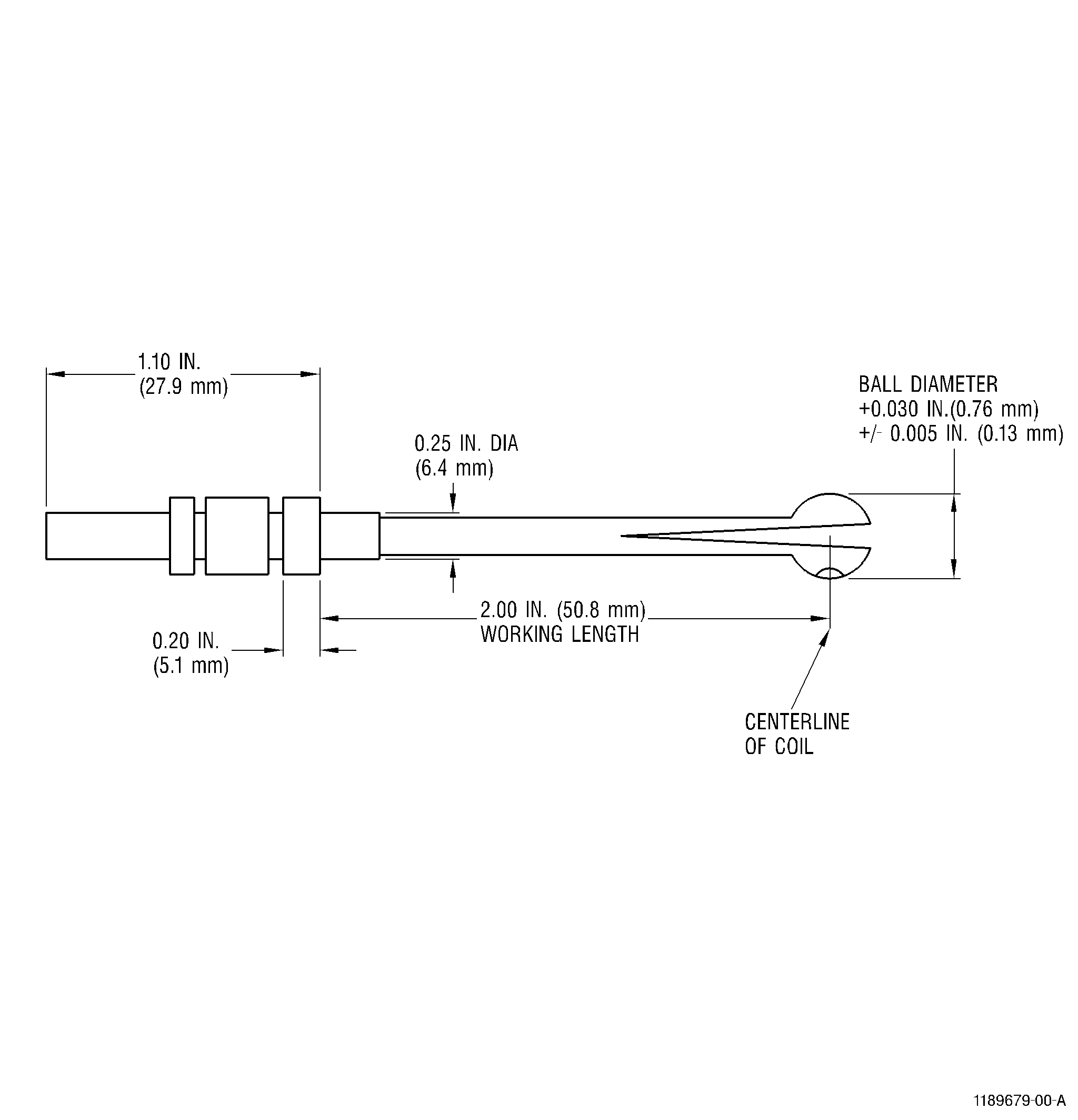
| (c) | Eddy Current Probe: SPO-5000 series or a GE-approved probe. The probe to be used will be specified in the appropriate approved Engine/Shop Manual or Service Bulletin for the specific hardware to be inspected. |
| NOTE: |
|
|
||||||||||||||||||||||||||||||||||||||||||||||||||||||||||||||||||||||||||||||||||||||||||||||||||||||||||||||||||||||||||||||||||||||||||||||||||||||||||||||||||||||||||||||||||||||||||||||||||||||||||||||||||||||||||||||||||||||||||||||||||||||||||||||||||||||||||||||||||||||||||||||||||||||||||||||||||||||||||||||||||||||||||||||||||||||||||||||||||||||||||||||||||||||||||||||||||||||||||||||||||||||
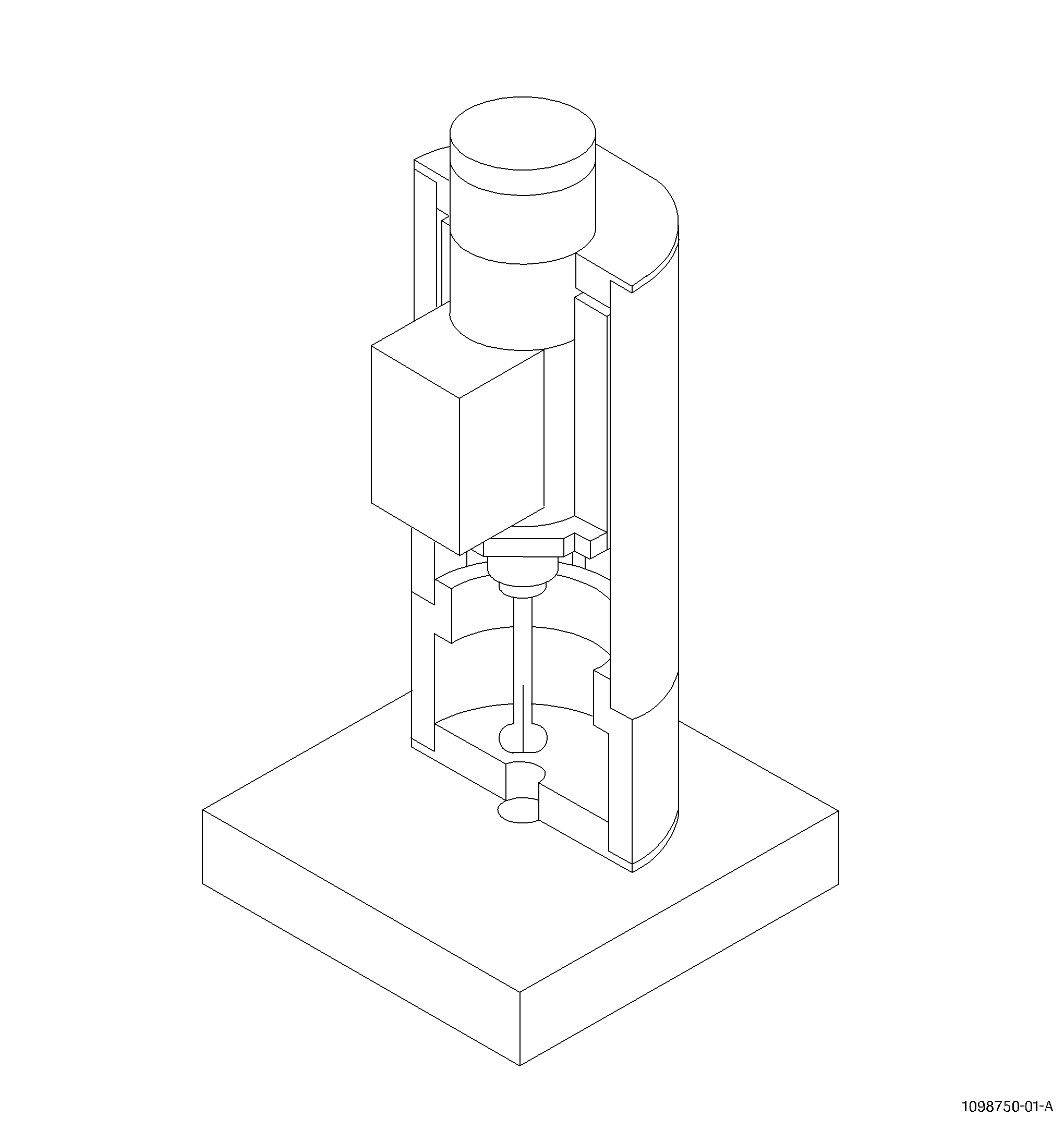
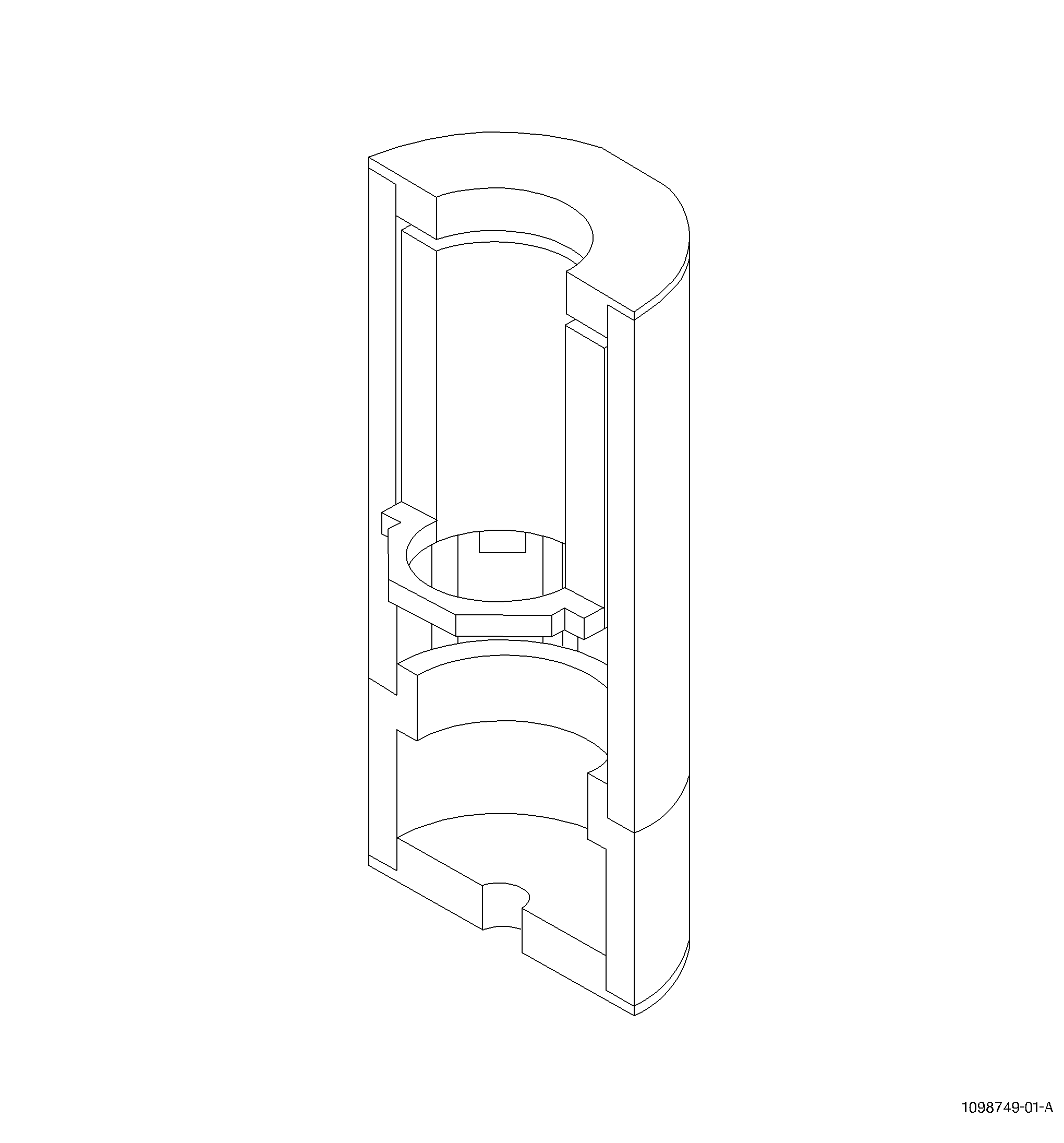
| (d) | Guide Fixture: An approved guide fixture must be used for all inspections to provide mechanical control of the probe angle. The guide fixtures are listed in Table 2 will be specified (by GE kit number) in the appropriate Service Bulletin or Engine/Shop Manual procedure. Refer to Figure 7. |
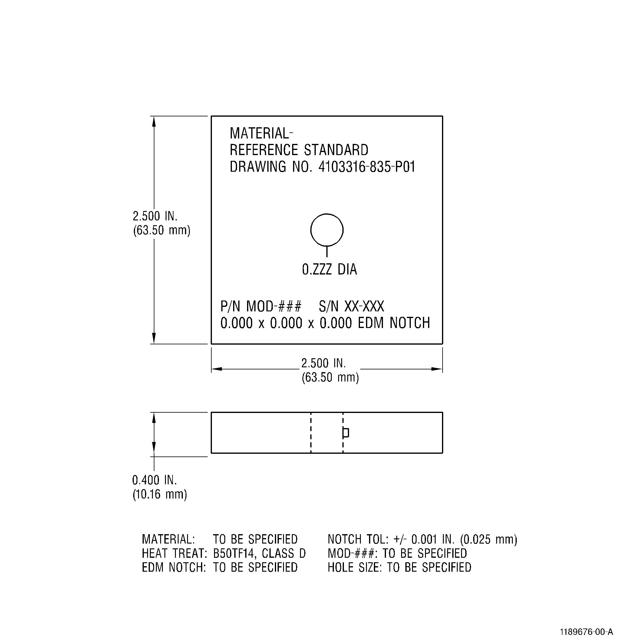
| (e) | Calibration Standard: Calibration standards will be specified in the appropriate Service Bulletin or Engine/Shop Manual procedure for the part to be inspected. Refer to Figure 6. |
| (f) | Mineral Oil: A small amount of mineral oil or other lubricant may be used to reduce friction for smoother probe rotation, reduced probe and standard wear, and less noise. It is important that the lubricant be a relatively inert material to avoid chemical reactions which may affect probe performance or reduce its useful life. The use of mineral oil or another lubricant is not required but is left to the discretion of the user. |
| (g) | Cleaning Materials: Approved cleaning materials and solvents should be used to make sure the part is clean before inspection. |
| (h) | Flex-Hones: Flex-Hones may be used when more aggressive cleaning is required and shall be specified in the appropriate Service Bulletin or Engine/Shop Manual procedure. |
| (i) | Marking Materials: Action Marker Q404, black, or equivalent, shall be used to perform any marking of hardware. |
| (5) | Pre-inspection Part Preparation. |
| (a) | Clean the holes to be inspected in accordance with TASK 70-22-06-110-043, Special Cleaning Procedure No. 6, Bolthole Cleaning for Eddy Current Inspection. |
| (b) | Number the holes for reference. The reference location for numbering is the “/” in the designation “S/N” where the part serial number is located. Hole number 1 is the first hole clockwise from the “/”, aft looking forward (ALF). If the “S/N” mark does not exist, the number 1 hole will be the first hole clockwise from the initial digit of the serial number. All remaining holes are then numbered in sequence moving clockwise, aft looking forward. |
| (c) | Visually inspect the holes under white light. Clean the holes again, as required, to remove any remaining dirt or foreign material. TASK 70-22-06-110-043, Special Cleaning Procedure No. 6, Bolthole Cleaning for Eddy Current Inspection. |
| (6) | Initial Equipment Setup. |
| (a) | Select the appropriate inspection kit, as specified in the Service Bulletin or Engine/Shop Manual procedure for the hardware to be inspected. |
| NOTE: |
|
| (b) | Install the eddy current probe rotor into the appropriate guide fixture. Refer to Figure 5. |
| (c) | Connect the cable from the probe rotor to the eddy current instrument. |
| (d) | Insert the probe in the calibration standard hole to check the probe fit. Refer to Figure 6 and Figure 4. It is necessary that the probe contacts the surface of the hole but there should be no interference or binding. Significant probe drag may slow or stop the rotor. |
| (e) | If the difference between the probe and hole diameters is too great, either too large or too small, it may be necessary to use a slightly larger or smaller probe. |
| NOTE: |
|
| (f) | Insert the probe into the probe rotor or probe adapter, as appropriate for the type of rotor being used. Refer to Figure 5. |
| (g) | Adjust the eddy current instrument to the initial settings, as specified in Table 1. |
| (7) | Equipment Calibration. |
| (a) | Turn on the probe rotor and apply a very small amount of mineral oil to the tip of the probe, if desired. |
| NOTE: |
|
| (b) | Place the guide fixture on the calibration standard, center it over the calibration hole, and translate the probe carefully into the hole. |
| (c) | With the probe placed well into the calibration hole but away from the electric-discharge machined (EDM) notch, null (compensate) the instrument. |
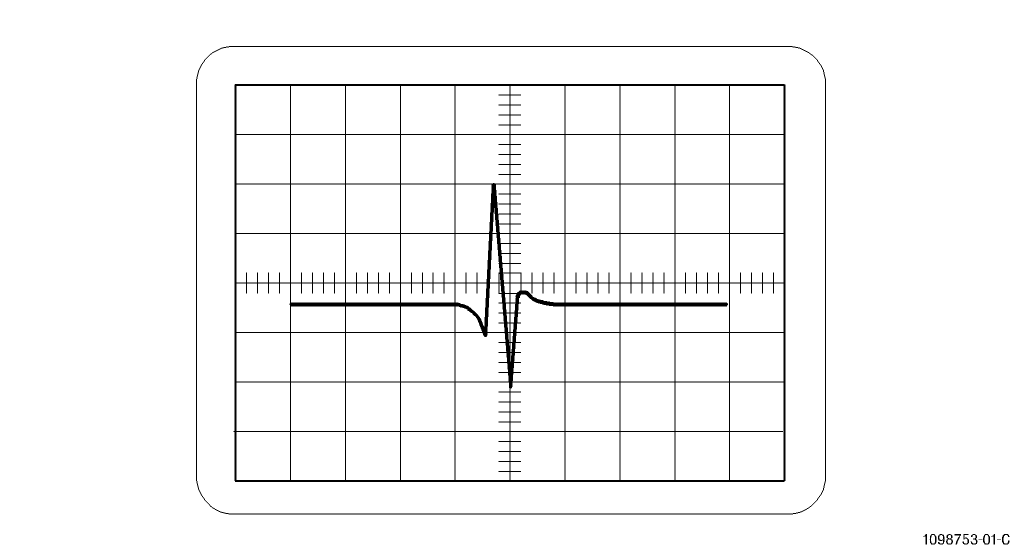
| (d) | Translate the probe through the hole until the notch signal is located. Refer to Figure 3. |
| (e) | Scan the length of the EDM notch and observe the response on the CRT. |
| (f) | Hold the rotor at the position where the largest notch signal response is obtained. |
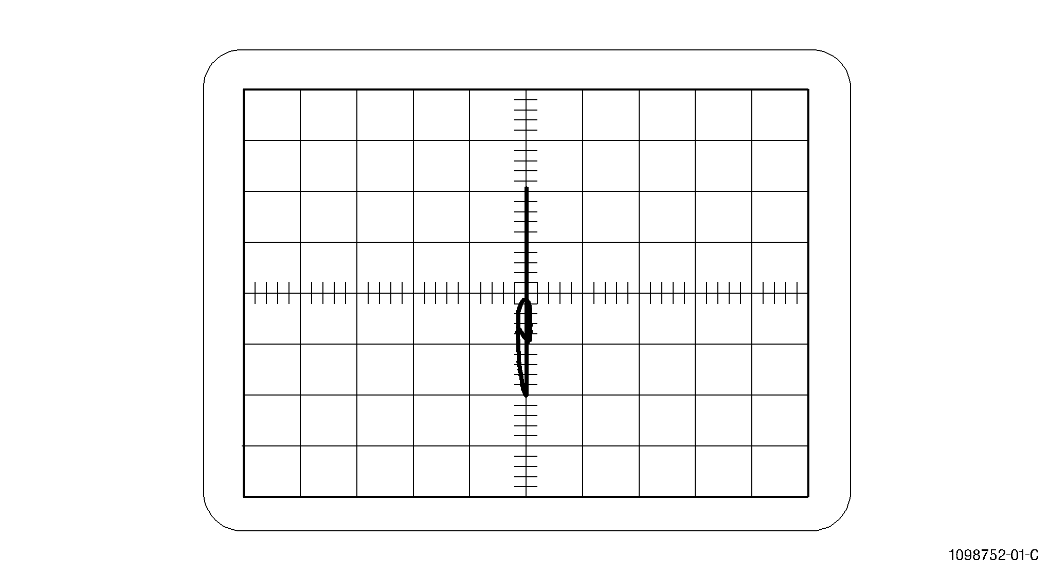
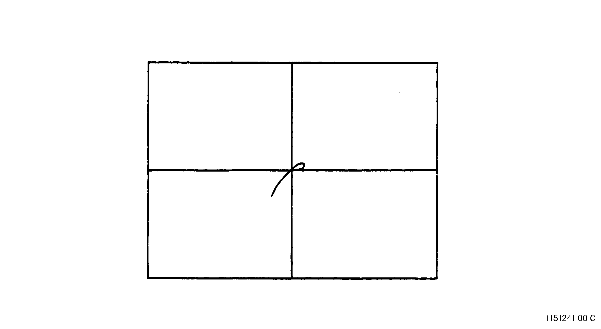
| (g) | Adjust the instrument phase (rotation) control to orient the notch signal vertically. Refer to Figure 3. |
| (h) | Adjust the gain control to produce a notch signal with a vertical peak-to-peak amplitude of four major screen divisions. It may be helpful to offset the dot position from the center of the screen as an aid in setting the correct notch signal amplitude. |
| NOTE: |
|
| (i) | Translate the rotor to scan the complete length of the notch to make sure that the calibration was performed at the location of the largest notch signal amplitude. |
| NOTE: |
|
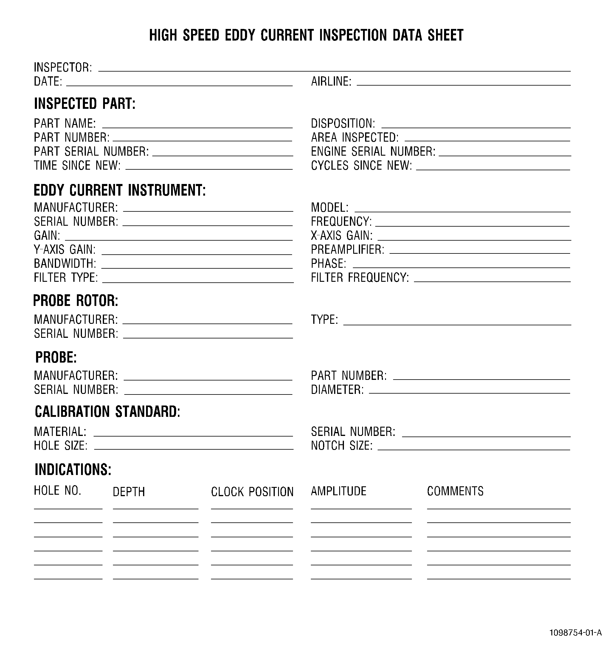
| (j) | Record the instrument calibration settings on the inspection data sheet, Form 699-1( Figure 2). |
| (8) | Hardware Inspection. |
| (a) | After completion of the instrument calibration, either the impedance plane (X/Y) or timebase (Y/T) display mode can be used during the inspection of hardware. Refer to Figure 3 and Figure 1. The gate and alarm may also be used if desired. |
| (b) | Remove the probe from the rotor and check the probe fit by inserting the probe into several randomly selected holes around the hardware. |
| 1 | It is necessary that the probe contacts the surface of the hole but there should be no interference or binding. |
| 2 | If the selected probe does not meet the criteria described in the proceeding paragraph, the probe may be worn or the hole may be oversized. Another probe should be selected. |
| NOTE: |
|
| (c) | Return the probe to the rotor and apply a small amount of mineral oil to the probe tip if desired. If required, adjust the leveling block at the bottom of the guide fixture to keep the probe perpendicular to the bolt hole. |
| (d) | Carefully center the probe over the first hole to be inspected and translate the rotor until the probe coil is well into the hole. |
| (e) | Null the eddy current instrument. |
| (f) | Translate the probe slowly down through the hole and back up again while observing the display of the eddy current instrument. The translation speed should be approximately 0.2 inch (5 mm) per second or less. At this speed the inspection of a hole which is 1.0 inch (25 mm) deep should take at least five seconds in each direction. |
| (g) | Monitor the eddy current instrument display and record any indications that exceed the inspection threshold requirements given in the appropriate Service Bulletin or Engine/Shop Manual procedure for the part being inspected. |
| (h) | Move to each subsequent hole and repeat the inspection process. Periodically reapply mineral oil to the probe tip, if needed. |
| (9) | Post-inspection Calibration Check. |
| (a) | A calibration check shall be performed upon the completion of each inspection, at least every hour, whenever any system component or the inspector is changed, or any time the inspector suspects a change may have occurred in the inspection system. |
| (b) | Return the guide fixture to the calibration standard. Center the fixture over the calibration hole, and move the probe carefully into the hole. |
| (c) | With the probe well into the hole and the coil away from the EDM notch, null the instrument. |
| (d) | Scan the length of the EDM notch and hold the rotor at the position where the largest notch signal response is obtained. |
| (e) | If the notch response obtained is four major screen divisions, ± one-half major division, the test is acceptable. |
| (f) | If the notch response has decreased by more than one-half major screen division, the system must be re-calibrated and any hardware inspected since the last acceptable calibration must be re-inspected. |
| (g) | If the notch response has increased by more than one-half major screen division, the system must be re-calibrated prior to the inspection of any additional hardware. Hardware inspected and determined to be acceptable since the last acceptable calibration need not be re-inspected. |
| (10) | Indication Evaluation/Rejection Criteria. |
| (a) | Evaluate any hole which, during the initial inspection, produced one or more indications exceeding the indication evaluation/rejection threshold requirements given in the appropriate Service Bulletin or Engine/Shop Manual procedure for the part being inspected. |
| (b) | Perform a calibration check as described in paragraph 2.A.(9), Post-inspection Calibration Check. |
| (c) | Repeat the inspection of the hole to relocate the indication and confirm that it exceeds the evaluation/rejection threshold requirements. |
| (d) | If the indication is confirmed, clean the hole using approved cleaning material. Refer to paragraph 2.A.(11), Cleaning Procedure. |
| (e) | Visually inspect the hole and record any unusual conditions which might affect the inspection results on the eddy current inspection data sheet, Form 699-1( Figure 2). |
| (f) | Repeat the inspection of the hole after cleaning. If the indication amplitude has reduced, repeat the cleaning process as necessary until the indication is removed or the amplitude of the eddy current indication is reduced below the evaluation/rejection limit. |
| (g) | If the indication cannot be reduced in amplitude to an acceptable level, or increases in amplitude as a result of the cleaning process, refer to paragraph 2.A.(12), Disposition, Documentation, and Records, and the appropriate Service Bulletin or Engine/Shop Manual procedure for the disposition of the hardware. |
| (11) | Cleaning Procedure. |
| (a) | Refer to TASK 70-22-06-110-043 , Special Cleaning Procedure No. 6, Bolthole Cleaning for Eddy Current Inspection. |
| (12) | Disposition, Documentation, and Records. |
| (a) | Any indication equal to or greater than the criteria specified in the appropriate Service Bulletin or Engine/Shop Manual procedure for the hardware being inspected shall be evaluated to the requirements of paragraph 2.A.(10), Indication Evaluation/Rejection Criteria. |
| (b) | If the amplitude of any indication, after evaluation, is still equal to or greater than the specified requirements, the hardware shall be considered reject and unserviceable. |
| (c) | If the inspection produces no indications equal to or greater than the specified requirements, the hardware shall be considered serviceable. |
| (d) | As a minimum, record the requested information on Form 699-1( Figure 2). |
| 3 . | Slow Speed Eddy Current Inspection (Method B). |
| Subtask 70-32-07-250-012 |
| A. | Method B: Slow Speed Eddy Current Inspection Method. |
| (1) | Scope. |
| (a) | This document describes the equipment, technique and procedure required to conduct 2 MHz slow speed eddy current inspections of circular holes in Inconel and titanium alloy engine hardware for the detection of cracking. A service bulletin or shop manual procedure must provide the detailed information needed for inspection of specific parts. |
| (b) | This document describes the general procedure and equipment which have been approved for the performance of slow speed eddy current hole inspections. Exceptions to this procedure may be required for specific cases where the procedure or equipment described here cannot be used or is not appropriate. Such exceptions should be obtained in writing from GE Aircraft Engines. |
| (2) | Applicable Documents. |
| (a) | Instruction manuals or other information provided by equipment manufacturers. |
| (b) | National Aerospace Standard 410 (NAS 410), which replaces MIL-STD 410, and/or American Society of Non Destructive Testing specification ASNT-TC-1A (ASNT-TC-1A). |
| (c) | The appropriate Service Bulletin or Engine/Shop Manual procedure. |
| (3) | Personnel Requirements. |
| (4) | Personnel performing this inspection must be certified in accordance with NAS 410, ASNT-TC-1A, Air Transport Association Specification No. 105 (ATA 105), or locally approved certification program. |
| (a) | Personnel performing this inspection should receive practical training in the use of this procedure and must demonstrate proficiency in calibration of the inspection equipment, inspection of hardware, and evaluation of indications before the authority to accept and reject hardware is delegated. |
| (b) | Any training which may be provided by GE Aircraft Engines for a technique requiring the performance of this inspection method does not imply that the personnel who receive that training have met the requirements for inspector certification in accordance with NAS 410, ASNT-TC-1A, or ATA 105. |
| (5) | Equipment Requirements |
| NOTE: |
|
| NOTE: |
|
| (a) | Eddy current instrumentation - one of the following types of equipment is required in order to accomplish these inspections or approved equivalent. |
| 1 | Nortec Model NDT-19/19E Eddyscope. |
| 2 | Nortec Model NDT-16 Eddyscope with Model A16-1 amplifier, Model 016-2 oscillator and either a Model F16-1 or Model FS16-1 or FS16-2 filter module. |
| 3 | Rohmann Elotest B1 SDM Eddyscope with Probe socket B1-NOB3H or B1-ANO2. |
| 4 | Nortec Model NDT-25L |
| (b) | Strip chart recorder: One of the following types of equipment is required in order to accomplish these inspections, or approved equivalent. (All recorders must have a minimum of 2 channels.) |
| 1 | Gould 220 recorder. |
| 2 | Gould TA240 recorder with two 13-6615-10A signal conditioners. |
| 3 | Gould Windowgraf with two 13-6615-10A signal conditioners. |
| 4 | Graphtech WR3310 recorder with two AL 3301 signal conditioners. |
| 5 | Graphtech WR7500 recorder with two AL3501 signal conditioners. |
| NOTE: |
|
| (c) | Strip chart recorder paper as required. |
| (d) | Connecting cables as required for Eddy current instrument, strip chart recorder, scanners, and controllers. |
| (e) | Bolthole Scanner: One of the following sets of scanner equipment is required to accomplish a bolt hole inspection. |
| 1 | Nortec model PS-2M scanner with model PS-2 speed control. |
| 2 | Nortec Model PS-3R scanner and PS-3T translator with respective controllers. |
| (f) | A rigid fixture for holding the Nortec bolthole scanners. Refer to paragraph 3.A.(4)(e), Bolthole Scanner. The fixture must have provision for positioning the scanner over the bolt or air holes and provision for adjustment so that the probe body can be set parallel to the axis of the bolt or air hole. |
| (g) | Inspection probe: GE-approved 2 MHz hole probe. Refer to Table 3. The correct probe size to be used will be given in the service bulletin or shop manual procedure for the part to be inspected. |
|
|||||||||||||||||||||||||||||||||||||||||||||||||||||||||||||||||||||||||||||||||||||||||||||||||||||||||||||||||||||||||||||||||||||||||||||||||||||||||||||||||||||||||||||||||||||||||||||||||||||||||||||||||||||||||||||||||||||||||||||||||||||||||||||||||||||||||||||||||||||||||||||||||||||||||||||||||||||||||||||||||||||||||||||||||||||||||||||||||||||||||||||||||||||||||||||||||||||||||||||||||||||||||||||||||||||||||||||||||||||||||||||||||||||||||||||||||||||||||||||||||||||||||||||||||||||||||||||||||||||||||||||||||||||||||||||||||||||||||||||||||||||||||||||||||||||||||||||||||||||||||||||||||||||||||||||||||||||||||||||||||||||||||||||||||||||||||||||||||||||||||||||||||||||||||||||||||||||||||||||||||||||||||||||||||||||||||||||||||||||||||||||
| (h) | Calibration standard: Calibration standards must be made of the same material as the part to be inspected. Standards must have a hole with an electrical-discharge-machined (EDM) notch cut in the side. Specific details about the dimensions of the calibration standard, the diameter of the hole or holes, and the size and location of the EDM notch will be specified in the service bulletin or Engine/Shop Manual procedure, for the part to be inspected. See Figure 6. |
| (i) | Marking materials: C05-104 Action Marker 44, black, or equivalent, to mark parts. |
| (j) | Rubber wedge material: Parkway Products, G.E. RTV583, 0.375 in. (9.53 mm) sheet thickness or equivalent such as an eraser. |
| (k) | Cleaning materials: Approved cleaning materials and solvents should be used to make sure the part is clean before inspection. |
| (l) | Teflon tape: maximum thickness 0.0035 inch (0.089 mm) 3M Company, number 5490, 0.25 in (6.35 mm) wide. |
| (6) | Pre-inspection - Part Preparation. |
| (a) | Clean the holes using approved cleaning materials. Refer to TASK 70-22-06-110-043, Special Cleaning Procedure No. 6, Bolthole Cleaning for Eddy Current Inspection. |
| (b) | Number the holes for reference. The reference location for numbering is the "/" in the designation "S/N" where the part serial number is located. Hole number 1 is the first hole clockwise from the "/", aft looking forward (ALF). If the "S/N" mark does not exist, the number 1 hole will be the first hole clockwise from the initial digit of the serial number. All remaining holes are then numbered in sequence moving clockwise, aft looking forward. |
| (c) | Visually inspect the holes under white light. Clean the holes again, as required, to remove any remaining dirt or foreign material. Refer to TASK 70-22-06-110-043 , Special Cleaning Procedure No. 6, Bolthole Cleaning for Eddy Current Inspection. Note on the appropriate inspection data sheet any significant physical conditions in the holes such as evidence of fretting or rubbing. |
| (7) | Equipment Set-up. |
| (a) | Set the instrument control settings in accordance with Table 4. |
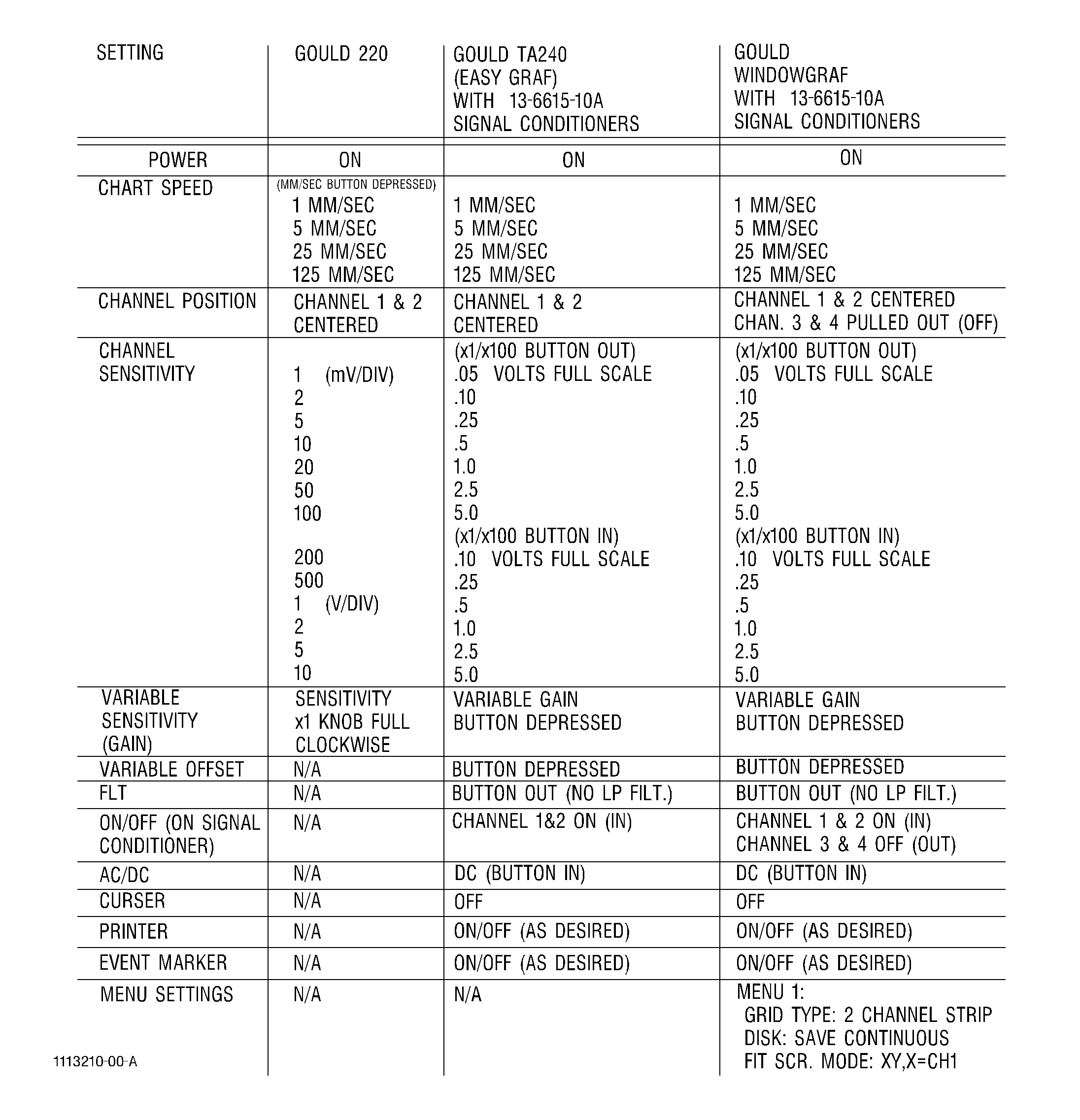
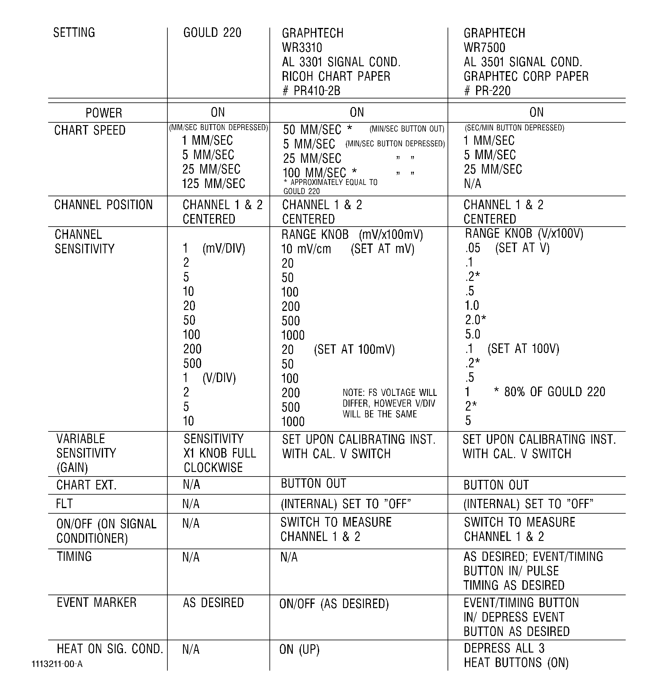
| (b) | Set the Gould model No. 220 to the settings in accordance with Table 4, or alternate recorder in accordance with Figure 13. |
| (c) | Adjust the rotational speed of the scanner so that it corresponds to the value noted in Table 3 for that diameter of bolt hole probe being used. |
|
|||||||||||||||||||||||||||||||||||||||||||||||||||||||||||||||||||||||||||||||||||||||||||||||||||||||||||||||||||||||||||||||||||||||||||||||||||||||||||||||||||||||||||||||||||||||||||||||||||||||||||||||||||||||||||||||||||||||||||||||||||||||||||||||||||||||||||||||||||||||||||||||||||||||||||||||||||||||||||||||||||||||||||||||||||||||||||||||||||||||||||||||||||||||||||||||||||||||||||||||||||||||||||||||||||||||||||||||||||||||||||||||||||||||||||||||||||||||||||||||||||||||||||||||||||||||||||||||||||||||||||||||||||||||||||||||||||||||||||||||||||||||||||||||||||||||||||||||||||||||||||||||||||||||||||||||||||||||||||||||||||||||||||||||||||||||||||||||||||||||||||||||||||
| (d) | Figure 13 provides equivalent settings for times when alternate recorders are used instead of the Gould 220. To use this table, refer to the Gould 220 initial settings in Table 4, find that setting in Figure 13 for the 220 then read across the table for the appropriate setting for the selected recorder. |
| NOTE: |
|
| NOTE: |
|
| (e) | For inspections being accomplished with a Nortec PS-3TR scanner, adjust the speed of translation on the PS-3T controller so that it has the value noted in Table 3 for the diameter of hole under inspection. |
| NOTE: |
|
| (f) | Connect the vertical output of the eddy current instrument to Channel No. 1 of the strip chart recorder and the horizontal output of the eddy current instrument to Channel No. 2. |
| (8) | Probe Preparation. |
| (a) | Select the appropriate size probe for the hole to be inspected as specified in the applicable service bulletin or shop manual procedure. Refer to Table 3. |
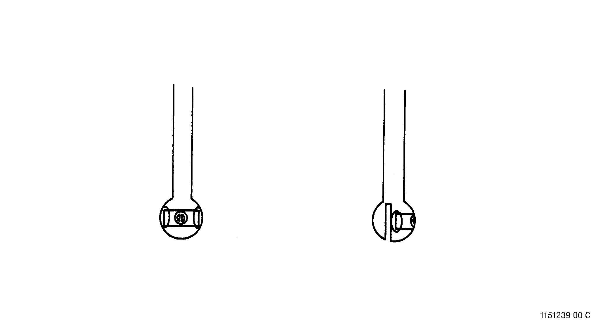
| (b) | Apply teflon tape to completely cover coil face. See Figure 12. |
| NOTE: |
|
| (c) | Manually insert the probe into the calibration hole to determine fit. Proper fit is achieved when the probe tip is snug enough that it will stand alone and supports it's own weight. On inserting or withdrawing the probe there should be a light drag. |
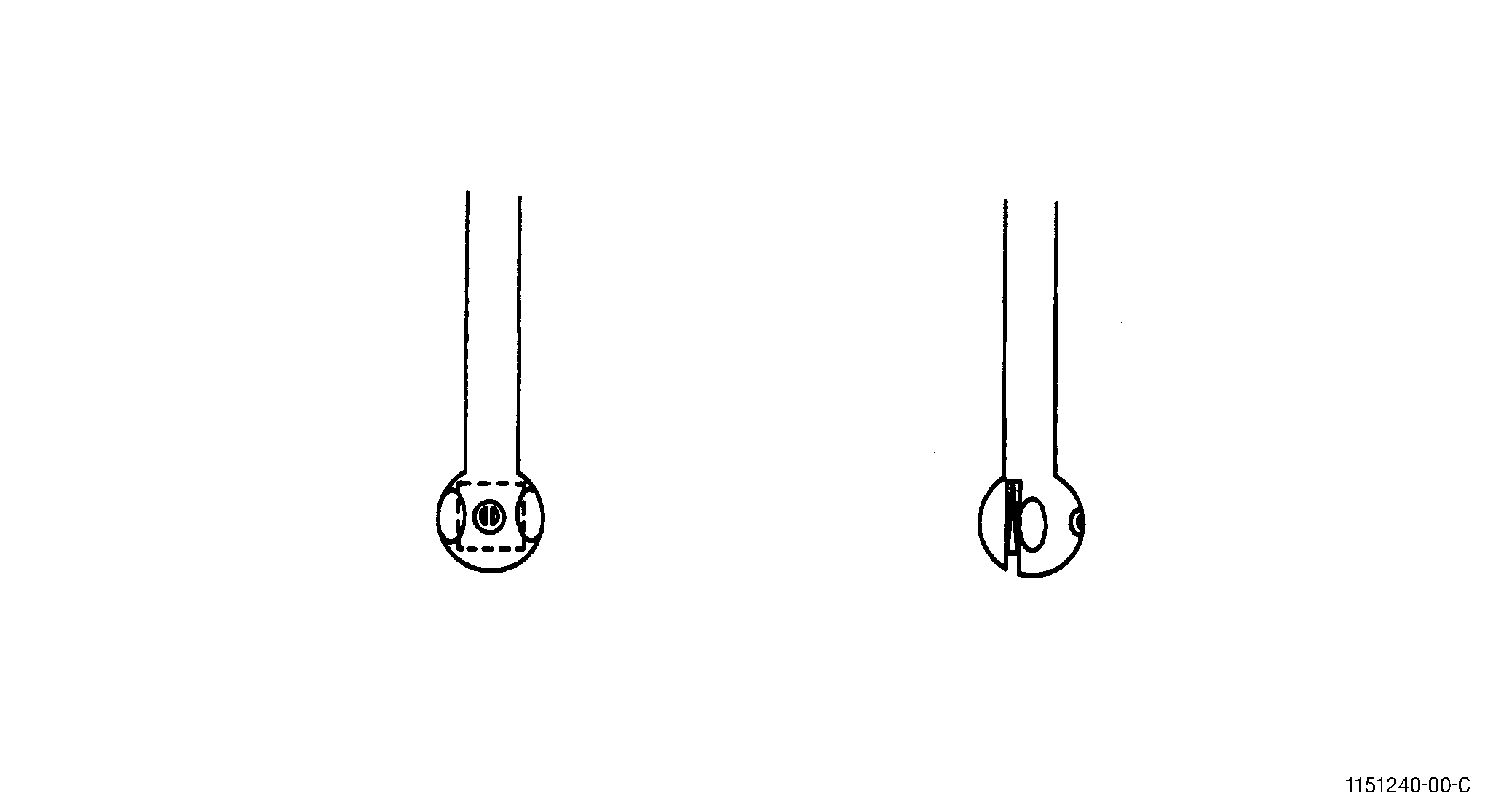
| (d) | For probes with saw slots, proper fit is obtained by cutting a piece of wedge rubber, at a slight wedge shape. Gross wedge shapes will work themselves out of the probe slot. Insert the rubber wedge into the probe slot and adjust for fit as described in paragraph 3.A.(7)(c). See Figure 11. |
| (e) | For probes without saw slots, proper fit is obtained by applying teflon tape as required to the probe body opposite the coil. |
| (f) | Insert probe into scanner. |
| (9) | Equipment Calibration. |
| CAUTION: |
|
| (a) | Connect the equipment and set the initial control settings per paragraph 3.A.(6) of this document. |
| 1 | Set up the NDT-16 as follows: |
| a | Remove the No. F16-1 filter module during set up of the equipment and carefully snap off the left side cover of the module. |
| b | Move the small slide switch inside the module near the front panel to position X1. |
| c | Replace the cover and reinsert the filter module. |
| 2 | Set up the Elotest B1 as follows: |
| a | Determine the maximum possible preamplifier gain by increasing the preamplifier gain until the "PREAMP OVERLOAD" indication appears. |
| NOTE: |
|
| b | Reduce the preamplifier gain just enough to eliminate the overload indication. |
| CAUTION: |
|
| c | To operate at higher preamplifier gain levels, tune the impedance bridge circuitry. Set the filter to 100 Hz high-pass and press the compensation (null) button. Change the filter back to 100 Hz low-pass. |
| d | Place the probe on a test piece or calibration standard. |
| e | Adjust the two small potentiometers on the adapter to move the dot as close as possible to the null point on the display. |
| NOTE: |
|
| f | If necessary, reduce the gain to bring the dot on screen so that this adjustment may be made. |
| NOTE: |
|
| 3 | No special preparation is necessary for the Nortec NDT 19, NDT 19E, or NDT 25L. |
| (b) | Prepare the probe as stated in paragraph 3.A.(7) of this document. |
| (c) | Align the probe and scanner for correct entry into the hole with the calibration notch. Refer to 3.A(4)(h) calibration standard. |
| (d) | Turn on the PS-2M or PS-3T and 3R probe scanner and drive the probe down into the calibration hole until the probe coil is completely within the hole. |
| (e) | Stop the scanner when the white epoxy line on the probe stem faces away from the EDM slot location. |
| (f) | Null the instrument. For NDT-16, null for 5 to 10 seconds or until the spot stabilizes in the center of screen. |
| (g) | With the probe still in the calibration hole, turn on the PS-2M (FWD) and put the transmission in R for rotate only. For PS-3T and 3R systems, turn on the PS-3R for probe rotation only. |
| (h) | Change the filter on the eddy current instruments: |
| 1 | On the NDT 16, set the filter to 5 Hz (high pass). |
| 2 | On the NDT 19 and 19E, leave the low pass filter at100 Hz, and set the high pass filter to 4 Hz or 5 Hz. |
| 3 | On the Elotel B1, change the filter from the low pass100 Hz to high pass 5 Hz. |
| 4 | On the NDT 25L, leave the low pass filter (SP-02) at 100 Hz, and set the high pass filter to 5 Hz. |
| (i) | Turn on the strip chart recorder and check that Channel No. 1 is on 20 mV/Div. and Channel No. 2 is on 50 mV/Div. |
| (j) | Translate the probe within the calibration hole until the EDM notch is detected. |
| (k) | Manually translate the rotating probe across the entire EDM notch 0.003 in. (0.08 mm) at a time to determine where the maximum amplitudes are achieved on Channel No. 1 and No. 2. |
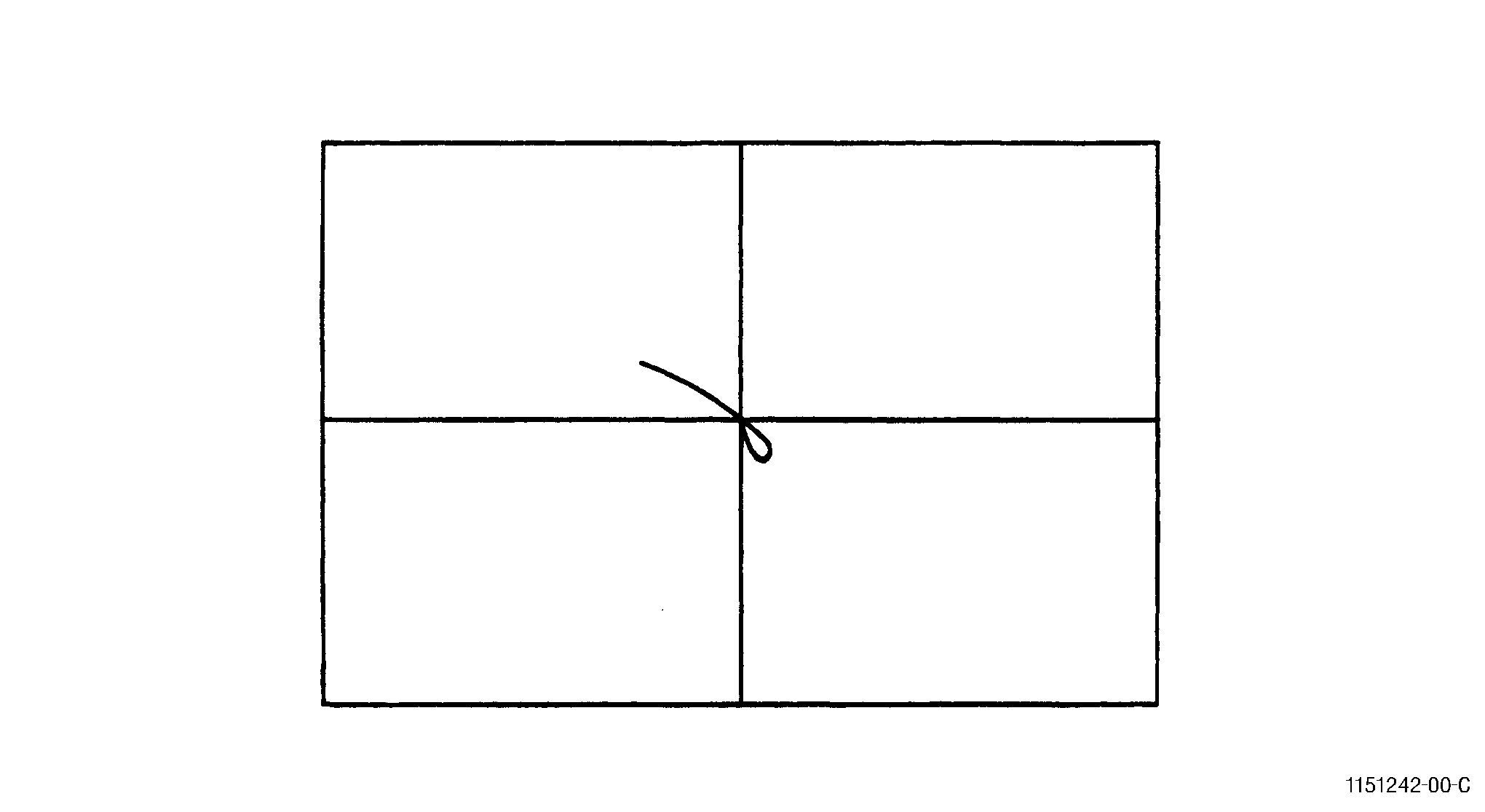
| (l) | Observe the EDM notch response on the eddyscope. Adjust the rotation or phase control to obtain an EDM notch response pointing(longest leg) into the upper left quadrant of the CRT for Inconel or into the lower left quadrant of the CRT for Titanium. See Figure 10 and Figure 9. In both instances the phase angle established by this step should be set to approximately 45 degrees from horizontal. |
| (m) | Examine the recorder tracings on Channels No. 1 and No. 2. Alternately adjust the rotation (Phase) and gain controls to achieve calibration amplitudes of 40 percent (400 mV) full scale on Channel No. 1 and 35 percent (875 mV) full scale amplitude in Channel No. 2 (plus or minus 1 percent full scale). Renull is required after any gain adjustment. Assure that the EDM notch response remains in the correct quadrant on the eddyscope. |
| NOTE: |
|
| NOTE: |
|
| NOTE: |
|
| (n) | When these amplitudes have been achieved, translate the probe very slowly across the entire notch to assure that the calibration has been performed at the point of maximum response from the notch. If a greater amplitude is obtained on the strip chart Channel No. 1 (vertical), repeat paragraphs 3.A.(8)(m) and (n). |
| (o) | If excessive noise is experienced on Channel No. 1 at the calibration settings, check for the following: |
| 1 | Teflon tape on probe face worn or damaged. |
| 2 | Probe not aligned with calibration hole. |
| 3 | Probe not wedged properly. |
| 4 | Calibration hole dirty. |
| 5 | Equipment malfunction (high gain). |
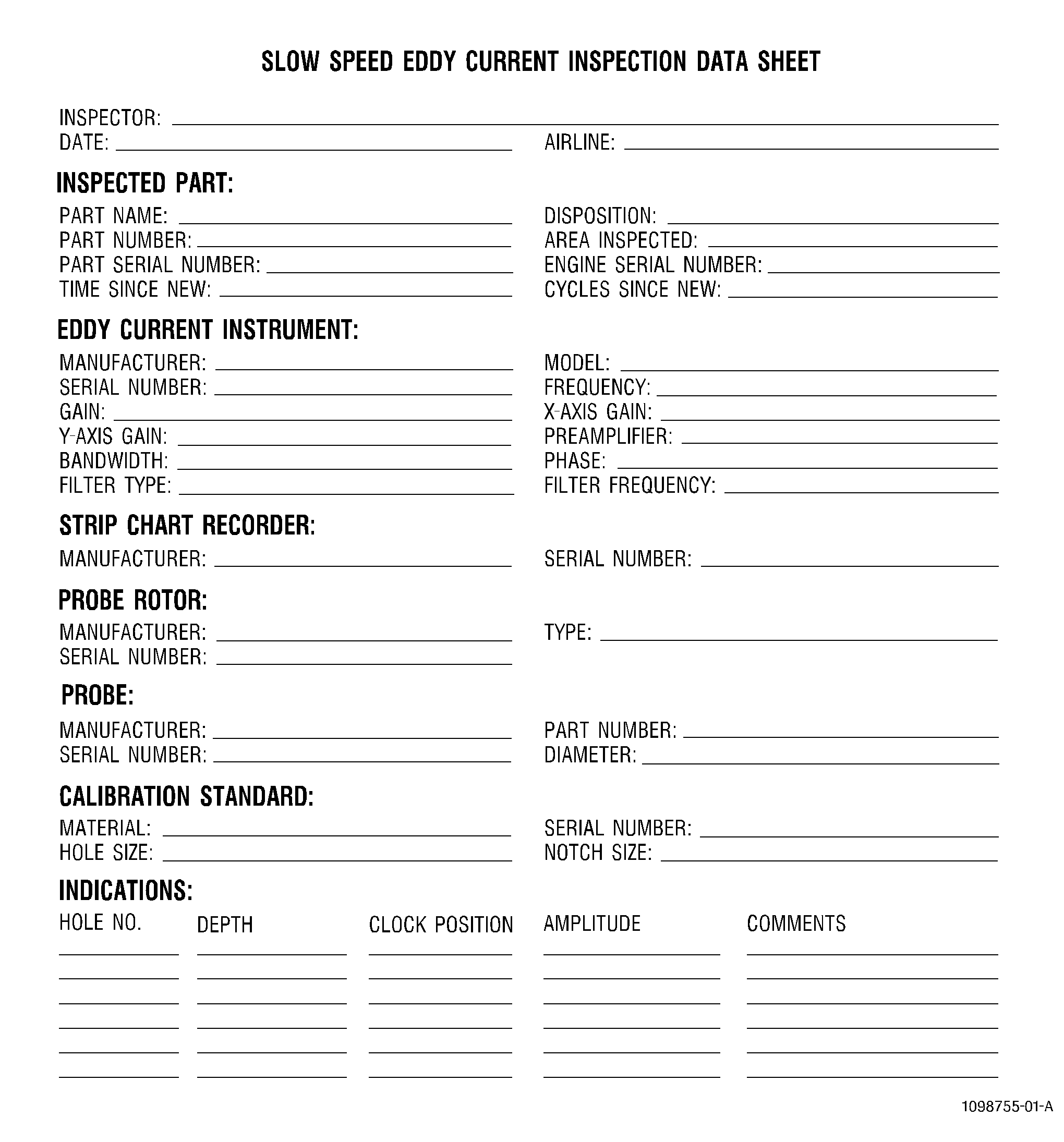
| (p) | Record all calibration data onto the strip chart recording and onto an appropriate inspection data sheet. See Figure 8. |
| (10) | Part Inspection |
| (a) | Assure the teflon tape is still covering the coil. Replace if it is worn or wrinkled, and recheck calibration. |
| (b) | Examine the probe fit in several holes and make whatever adjustments are necessary to ensure a fit which is equivalent to that obtained for calibration. Holes may be over or undersize and it may be desirable to inspect all the holes of one size before changing the diameter of the probe if it is required. |
| (c) | Scan all holes in the upward direction (translation) unless otherwise specified. |
| NOTE: |
|
| (d) | If any indications exceeding the requirements of paragraph3.A.(11) of this document are found, mark the hole for evaluation. |
| (e) | After all holes have been inspected, evaluate the indications from paragraph 3.A.(9)(d) per paragraph 3.A.(12) of this document. |
| (f) | Complete the post-inspection check per paragraph 3.A.(10) of this document. |
| (11) | Post-inspection Calibration Check. |
| (a) | After completion of the part inspection, or after intervals not to exceed four hours, check the calibration on the calibration standard. |
| (b) | If the calibration repeats within ±5 percent of full scale at channel No.1 of the strip chart recorder the test is acceptable. |
| (c) | If the amplitude of the response on Channel No. 1 has decreased by 5 percent of full scale amplitude, repeat the calibration procedure and reinspect all parts inspected since the previous calibration. |
| (d) | If the amplitude of the response on Channel No. 1 has increased by more than 5 percent, only parts previously found to be rejected to paragraph 3.A.(11) need to be reinspected, repeat the calibration procedure prior to additional inspection. |
| (12) | Inspection Requirements. |
| (a) | Any indication equal to or greater than the criteria specified in the service bulletin or Engine/Shop Manual procedure for the part being inspected must be evaluated according to the requirements of paragraph 3.A.(12). |
| (b) | If, after completion of the evaluation procedure, the amplitude of any indication is still equal to or greater than the requirements of the service bulletin or Engine/Shop Manual procedure, the part must be considered unserviceable. |
| (13) | Indication Evaluation. |
| NOTE: |
|
| (a) | Examine the traces on Channel No. 1 of the strip chart for each hole. For each hole with an indication(s) meeting the requirements of paragraph 3.A.(11), reclean the hole with a cotton swab moistened with cleaning fluid, and reinspect the hole. If the indication remains, it is considered repeatable, and should be evaluated as stated below. If not, proceed to next indication. |
| (b) | For all repeatable indications record the hole number, Channel No. 1 amplitude on the recorder and the location within the hole on the appropriate inspection data sheet. |
| (c) | Carefully examine the area under evaluation with a bright white light, using a glass of 2 to 10 power. Note any unusual conditions, such as discoloration, scratches, score marks, sharp edges, uneven surfaces, etc. Record these conditions on the appropriate inspection data sheet. |
| (d) | Carefully reclean the area containing the indication per paragraph 3.A.(5) of this document. Assure that no protruding material exists in the area. |
| (e) | Check that the probe fits snugly in the hole, and that the hole has not become elliptical. |
| (f) | Assure that the calibration amplitude is 40 percent full scale on Channel No. 1 and 35 percent full scale amplitude on Channel No. 2. Assure that the EDM notch is in the correct quadrant on the eddyscope. |
| (g) | Repeat the inspection of the hole. If the indication amplitude has reduced, repeat the cleaning process as necessary until the indication is removed or the amplitude of the eddy current indication is reduced below the evaluation limit. |
| (h) | If the indication cannot be reduced in amplitude to an acceptable level, or increases in amplitude, as a result of the cleaning, refer to paragraph 3.A.(11) and the appropriate service bulletin or shop manual procedure for information regarding the disposition of the part. |
| (14) | Records |
| (a) | As a minimum, the following information must be permanently written on each strip chart recording and an appropriate inspection data sheet. |
|
| 4 . | High Speed Eddy Current Inspection Method with Electronic Data Acquisition and Storage (Method C). |
| Subtask 70-32-07-250-013 |
| A. | Method C: High Speed Eddy Current Inspection with Electronic Data Acquisition and Storage. |
| (1) | Scope. |
| (a) | This document describes the equipment, technique, and procedure necessary to perform a 2 MHz high speed eddy current inspection with electronic data acquisition of circular holes in engine hardware. A Service Bulletin or Engine/Shop Manual procedure shall provide the detailed information needed for inspection of specific parts. |
| (b) | Perform the inspection of the hardware in accordance with Subtask 70-32-07-250-011, High Speed Eddy Current Inspection (Method A), and the following parameters. |
| (2) | Applicable Documents. |
| (a) | All documents listed in paragraph 2.A.(2), Applicable Documents, are to be followed. Refer to Subtask 70-32-07-250-011, High Speed Eddy Current Inspection (Method A). |
| (3) | Personnel Requirements. |
| (a) | Personnel performing this inspection must be certified in accordance with one of the requirements listed in paragraph 2.A.(3), Personnel Requirements. Refer to Subtask 70-32-07-250-011, High Speed Eddy Current Inspection (Method A). |
| (4) | Pre-inspection Part Preparation. |
| (a) | Pre-inspection part preparation is to be performed in accordance with Subtask 70-32-07-250-011 , High Speed Eddy Current Inspection (Method A). |
| (5) | Equipment Requirements. |
| CAUTION: |
|
| (a) | Holescan system: Rohmann GmbH ScanAlyzer or a GEAE-approved equivalent. The Holescan/ScanAlyzer eddy current inspection system is a universal software program to analyze, record and file data of image generating eddy current inspections. The ScanAlyzer system includes the following recommended components: |
| 1 | Computer - IBM-compatible PC, with Pentium processor > 200 MHz, main memory > 32 MB, monitor - SVGQ graphic card (256 colors > 800 x 600 pixel) 1024 x 786 recommended, operating system - Windows NT operating system with Service Pack 3 or higher, Elotest PC4 digitizing PC-card (type PC4/0, PC4/1, or PC4/2) and all associated software, or an approved equivalent. |
| 2 | Eddy current instrument - Rohmann Elotest B1/V4 or latest version with model B1-RS probe adapter. |
| 3 | Guide fixture - A GEAE-approved guide fixture, P/N SO16602, to provide mechanical control of the probe angle. |
| 4 | Probe rotor - SR1-HF Rohmann ScanAlyzer rotation scanner with analog or digital position identification, or an approved equivalent. |
| 5 | Cable - Rohmann GmbH model RK-2N cable, or an approved equivalent. |
| 6 | Probe Adapter - ARM1 for Rohmann rotor, or an approved equivalent. |
| (b) | Probe: GE Aircraft Engines (GEAE) SPO-5000 series probe or an approved equivalent. The correct probe size will be specified in the Service Bulletin or Engine/Shop Manual procedure for the part to be inspected. Refer to Figure 4. |
| (c) | Calibration Standard: Calibration standards must be made of the same material as the part to be inspected. Specific details will be specified in the Service Bulletin or Engine/Shop Manual procedure for the part to be inspected. Refer to Figure 6. |
| (d) | Mineral Oil: A small amount of mineral oil or other GEAE-approved lubricant can help produce a smoother probe rotation, reduce probe wear, and reduce incorrect eddy current signals. It is important that the lubricant be a relatively inert material to avoid chemical reactions that may affect probe performance or reduce its useful life. The use of mineral oil or another lubricant is not necessary but can be used at the discretion of the inspector. |
| (e) | Cleaning Materials: Use GEAE-approved cleaning materials and solvents to make sure the part is clean before inspection. |
| (f) | Marking Materials: Action Marker P/N Q404, black, or a GEAE-approved equivalent, to mark parts. |
| (g) | Flex-Hones: Flex-Hones may be used when more aggressive cleaning is required and shall be specified in the appropriate Service Bulletin or Engine/Shop Manual. |
| (h) | Inspection Shoes: A dedicated inspection fixture (shoe) for each piece of hardware has been designed to help facilitate inspection of the boltholes. It is recommended that inspection be performed using the inspection shoes. A list of approved inspection shoes can be obtained from GEAE. |
| (6) | Initial Equipment Setup. |
| (a) | Make all necessary cable connections for system operation. |
| (b) | Select the appropriate eddy current probe and calibration standard for inspection. |
| (c) | Insert the probe into the calibration standard hole to check the fit. It is desirable to have the probe lightly touch the surface of the hole but there should be no interference or binding. The motor in the probe rotor is very low torque so any drag will slow or stop the rotor. |
| 1 | If the difference between the probe and hole diameter is too great, either too large or too small, it may be necessary to use a slightly larger or smaller probe. |
| (d) | Insert the probe into the probe rotor. |
| CAUTION: |
|
| (e) | Adjust the Rohmann Elotest B1/V4 controls in accordance with the settings given in Table 5. |
| (f) | Adjust the Holescan system controls: |
| 1 | Using the DEVICE SETUP menu in the APPLICATIONS MANAGER menu, adjust the ScanAlyzer controls in accordance with the settings given in Table 6, Table 7, and Table 8. |
| (g) | Recommended filter settings for certain probe diameters are given in Table 9. |
| NOTE: |
|
|
||||||||||||||||||||||||||||||||||||||||||||||||||||||||||||||||||||||||||||||||||||||||||||||||||||||||||||||||||||||||||||||||||
|
||||||||||||||||||||||||||||||||||||||||||||||||||||||||||||||||||||||||||||||||
|
|||||||||||||||||||||||||||||||||||||||||||||||||||||||||||||||||||||||||||||||||||||||||||||||||||||||||||||||||||||||||||||||||||||||||||||||||||||||||||||||||||||||||||||||||||||
|
|||||||||||||||||||||||||||||
|
|||||||||||||||||||||||||||||||||||||||||||||||||||||||||||||||||||||||||||||||||||||||||||||||||||||||||||||||||||||||||||||||||||||||||||||||||||||||||||||||||||||||||||||||||||||
| (7) | Equipment Calibration. |
| NOTE: |
|
| (a) | Equipment calibration is to be performed in accordance with Subtask 70-32-07-250-011, High Speed Eddy Current Inspection (Method A). |
| (8) | Hardware Inspection. |
| (a) | Attach the appropriate inspection shoe to the guide fixture for inspection of boltholes. |
| (b) | Hardware inspection is to be performed in accordance with Subtask 70-32-07-250-011, High Speed Eddy Current Inspection (Method A). |
| (9) | Post-inspection Calibration Check. |
| (a) | Remove the inspection shoe from the guide fixture before post-inspection calibration check. |
| (b) | Post-inspection calibration is to be performed in accordance with Subtask 70-32-07-250-011, High Speed Eddy Current Inspection (Method A). |
| (10) | Indication Evaluation/Rejection Criteria. |
| NOTE: |
|
| (a) | Evaluation and rejection of hardware is to be performed in accordance with Subtask 70-32-07-250-011 , High Speed Eddy Current Inspection (Method A). |
| (11) | Cleaning Procedure. |
| (a) | Refer to TASK 70-22-06-110-043 , Special Cleaning Procedure No. 6, Bolthole Cleaning for Eddy Current Inspection. |
| (12) | Disposition, Documentation, and Records. |
| (a) | Disposition, documentation, and record keeping are to be performed in accordance with Subtask 70-32-07-250-011, High Speed Eddy Current Inspection (Method A). |