| COMMERCIAL ENGINE STANDARD PRACTICES MANUAL | Dated: 04/01/2006 | |
| SPM 70-46-02 DRYING OF THERMOSETTING COMPOSITE MATERIALS | ||
| COMMERCIAL ENGINE STANDARD PRACTICES MANUAL | Dated: 04/01/2006 | |
| SPM 70-46-02 DRYING OF THERMOSETTING COMPOSITE MATERIALS | ||
| TASK 70-46-02-360-002 |
| 1 . | Introduction. |
| A. | This Standard Practice is based on information contained in Aerospace Recommended Practice (ARP) 4977 and describes standard methods for drying composite structures prior to repair and gives general guidelines on use and applicability. |
| B. | This Standard Practice includes the removal of liquids that have collected inside the structures through open damage, microcracks or porosity and the removal of absorbed moisture from the composite material. |
| C. | The following definitions are used: |
| (1) | Visible Liquids. Visible liquids are split into two categories: |
| (a) | Liquids that dry in open air or under heat, leaving no residue or residue that can be easily wiped away and cleaned using the standard methods described in TASK 70-46-01-350-030, Masking and Cleaning of Epoxy and Polyester Matrix Thermosetting Composite Materials. Water and solvents are the most commonly found types. |
| (b) | Liquids that do not dry with standard methods but leave a residue or some remaining liquid that standard cleaning methods will not remove. The most common types are hydraulic fluid and jet fuel. |
| NOTE: |
|
| (2) | Absorbed Moisture: Composite structures tend to saturate with moisture in humid environments. The moisture level, if too high, could be detrimental to the quality of a bonded repair. It is necessary to dry areas that will be in contact with the repair bond surface area, including SPD parts and materials. Dry honeycomb replacement pieces before use if absorbed moisture can be present. |
| D. | Some types of composites can also absorb water or solvents used in cleaning (Aramid reinforced laminates and honeycomb absorb more). Use a method for absorbed moisture removal to make sure that solvent has completely evaporated in a shorter time. A bond completed before all the solvent has evaporated can cause low bond strength. |
| 2 . | General Drying Information. |
| A. | Drying a composite structure will in general consist of: |
| (1) | Removing visible liquids. |
| (2) | Cleaning (when liquid is other than water) and removing any permanently contaminated area. |
| (3) | Drying to obtain a visually dry structure before proceeding with the repair area preparation. |
| (4) | Performing the final drying before bonding. |
| B. | Visible Liquid |
| (1) | Description |
| Liquid can collect on structures or inside through existing openings or damaged areas. It can generally be removed with absorbent cloths, vacuum, or by blowing with compressed air (when it is water). |
| Liquid can also be found inside sandwich panels as the result of skin damage, delamination, debonding, skin microcracks, skin porosity, or a combination of these cases. In acoustic liners the perforated facesheets in the acoustically treated area can also allow moisture into the part. |
| Visible liquid in honeycomb panels can cause damage due to freezing (water), to corrosion of aluminum honeycomb, or to a possible reduction in structural strength if left for a long period of time. There is also a risk of steam pressure build up during a hot bond repair causing delamination or debonding. |
| Unlike water, other fluids can deteriorate not only the honeycomb and honeycomb/skin bond line, but also the skins. Degradation should be suspected when the substrate shows discoloration that cannot be removed by the drying methods given in this Standard Practice. |
| Removal of liquid from honeycomb panels will usually require the cutting of one skin to obtain access. Contaminated areas that cannot be cleaned will also have to be removed. |
| When degradation of the honeycomb or honeycomb/skin bond line is suspected, the honeycomb must be replaced. |
| Before proceeding with the repair area preparation, the structure must be clean and visually dry. |
| (2) | Visible liquid Detection |
| Liquid can be detected visually on or inside structures and in open damage. |
| The presence of liquid inside honeycomb panels must be suspected when debonding is found or when the surface is in a poor condition (paint deterioration and/or erosion) or shows signs of porosity. A discoloration of the composite is usually the indication of contamination. |
| Nondestructive Testing Inspection (NDI) methods such as thermography, ultrasonic checks, or X-rays can confirm the presence of trapped liquid. On glass or aramid structures, moisture meters can also be used. |
| (3) | Removal Methods |
| Depending on the type of fluid and on the location and time available, various methods may be used. |
| Mopping, vacuuming, blowing compressed air, and vacuum bagging the affected area are possible methods for water removal Refer to Step 4.A. for details of the methods. Mopping and vacuuming are also commonly used for the removal of liquids other than water. A thorough cleaning should follow - refer to TASK 70-46-01-350-030, Masking and Cleaning of Epoxy and Polyester Matrix Thermosetting Composite Materials. If the cleaning is not successful, the contaminated area shall be removed. |
| (4) | Drying Time |
| The criteria are to have a clean and visually dry structure. The time required will depend on the method used. |
| (5) | Control Methods |
| A visual inspection will usually show if all the liquid has been removed. On honeycomb panels, standard nondestructive methods can be used to confirm removal. If necessary cut open additional cells. |
| With liquids other than water, once the area is visually clean, local heating, not greater than 176°F (80°C), can help reveal more absorbed fluid due to the tendency of fluid to seep to the skin surface during heating. A water break test will confirm the cleanliness of the structure. Refer to the water break test method in TASK 70-46-01-350-030, Masking and Cleaning of Epoxy and Polyester Matrix Thermosetting Composite Materials. |
| C. | Absorbed Moisture |
| (1) | Description |
| Composites, as a result of their chemical structure, will absorb moisture when in contact with humid air. The absorption can reach a maximum value (saturation) that depends on the resin system and fiber reinforcement used (carbon, aramid, or glass), on the temperature and on the humidity of the surrounding air. Saturation values can range from 1 to 3% by weight. Nonmetallic honeycomb will generally reach saturation at a higher value, for example up to 5% for Nomex honeycomb. This moisture saturation combined with a hot environment (hot/wet condition) is one of the most adverse conditions met by a structure. It is taken into account at the design stage and in the testing of the main components. |
| The effect of moisture during a repair will depend mainly on the curing time and temperature and to a lesser extent on the repair and parent materials. The strength characteristics of the bond line and the repair patch quality could be affected. |
| Experience has shown that, for repair purposes, complete drying of a composite structure is not necessary. A dry surface will in general be sufficient provided it remains dry for the complete cure cycle. Moisture migration back to the surface during the cure cycle should be taken into account to determine the drying time and temperature. One way of ensuring a dry surface is to carry out a final drying cycle (after the laminate appears dry) at the temperature of the cure for the time of the cure. |
| Because only the surface of the laminate will be dried, the drying must take place after all stepping, scarfing, or other material removal steps have been completed. |
| The repair should be accomplished as soon as possible after drying because the moisture in the laminate will return to the surface at room temperature over a period of time. |
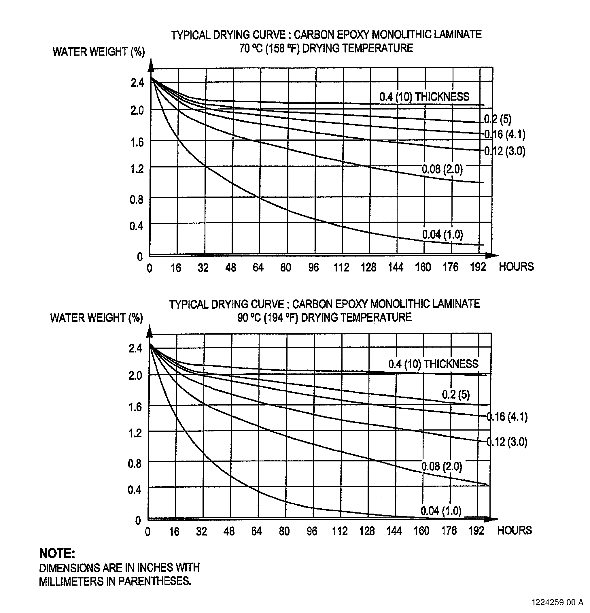
| Figures 1 and 2 are given to illustrate the length of time typical laminates take to absorb moisture and the time to completely remove all absorbed moisture. These figures are given for information and education only and should not be used to determine drying cycle time and temperature. The slow migration of moisture explains why surface drying is used and shows the importance of drying after material removal. |
| Figure 1 shows the average moisture content plotted against drying time of a composite laminate first saturated with moisture and then dried. The curves represent laminates of different thicknesses. Graphs for two different drying temperatures are shown. |
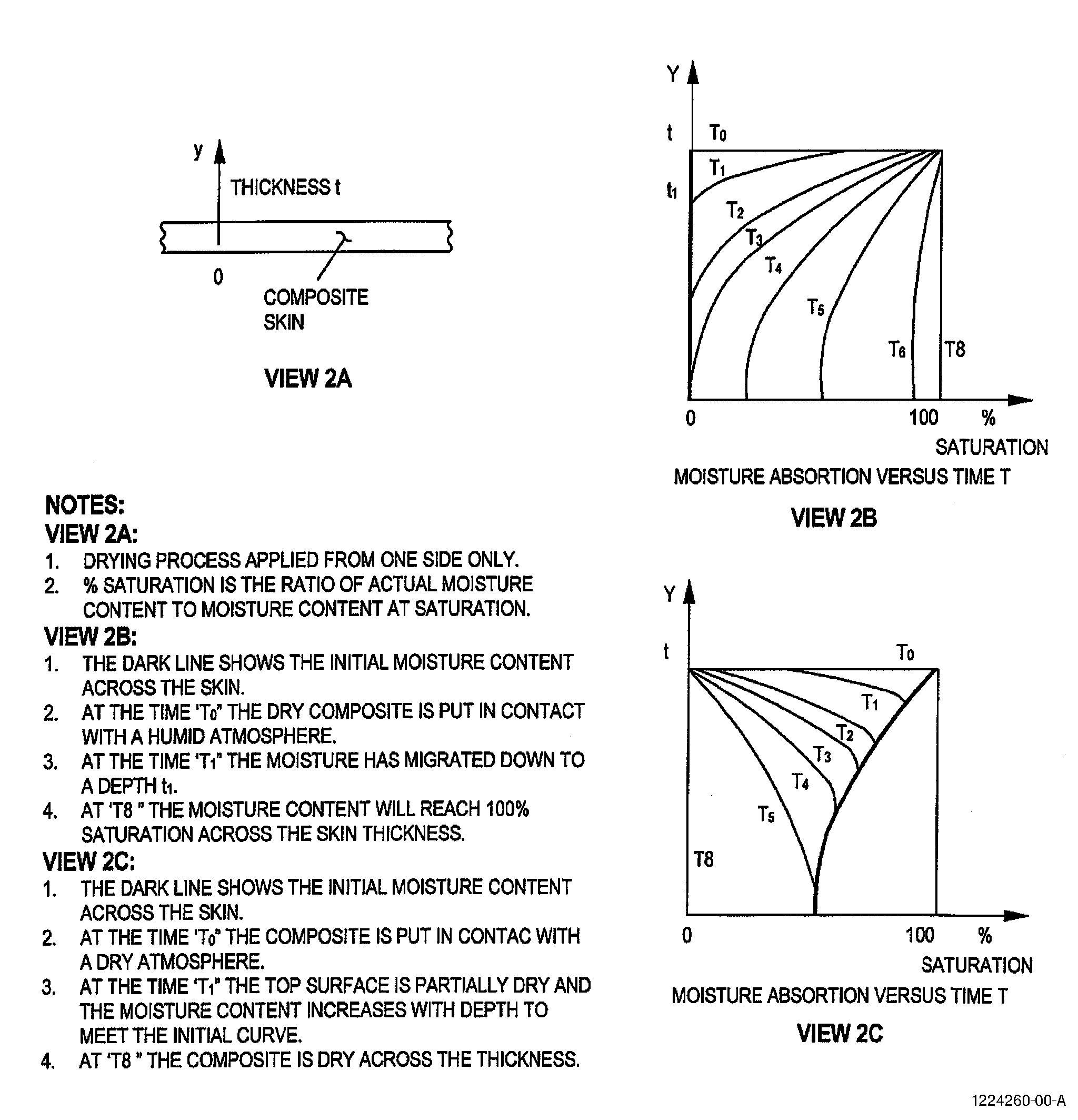
| Figure 2 shows a graphical representation of the percentage saturation across a laminate thickness at different times. |
| Figure 2 View 2B represents the values for a skin initially dry and exposed to humid atmosphere from one side. |
| Figure 2 View 2C represents the values for a skin initially saturated and then dried. |
| Absorption and desorption time are affected by the composite skin thickness, material type, temperature, and relative humidity. |
| (2) | Low Temperature Repairs - Temperature less than 212°F (100°C) |
| There is little data available today about low temperature cure repairs on moisture saturated structures. Nevertheless, the effect of moisture has been found to be minor in real repair conditions where there is always a period of time when the repair area can dry in open air. This natural drying time occurs in addition to the final drying recommended for all repairs. |
| Care should be taken with repair resin systems that cure at temperatures slightly below the boiling point of water. Even though the cure is monitored closely, when using heating blankets the temperature could rise locally above the boiling point. In addition, the boiling point will drop due to the lower atmospheric pressure inside the vacuum bag. For this reason when a structure is found soaked with water, once this water is removed and the structure is visually dry, it is necessary to perform a final drying before bonding. |
| (3) | High Temperature Repairs - Temperature more than 212°F (100°C) |
| A high moisture level will generally affect the repair lay-up bond to the structure and the repair patch quality. Additionally there is a high risk of debonding/delamination in areas outside the repair area if the whole part is to be heated. |
| When performing a high temperature repair it is necessary to have a dry structure. |
| The moisture content of the structure is generally unknown and could be suitable for high temperature repairs without any further drying. Nevertheless, when water is suspected to have been inside the structure for a long period of time, it is essential to perform a final drying before bonding. Dry the part after the repair area preparation on a visually dry structure. |
| 3 . | Drying Parameters. |
| A. | Drying Temperature |
| Unless otherwise specified in the repair, heat the part to 140 to 180°F (60 to 82°C) at a rate of temperature rise of approximately 5°F (3°C) per minute. |
| B. | Drying Time |
| Unless otherwise specified in the repair use the following times. |
| (1) | Low Temperature Repairs |
| After all visible moisture has been removed, apply heat to the part for a minimum of 1 hour to remove absorbed moisture and to make a dry surface layer. |
| (2) | High Temperature Repairs |
| After all visible moisture has been removed, heat the part to the repair cure temperature and hold at that temperature for the time of the cure. Take special care to use the same repair conditions (the same jig, tool, heat application methods, vacuum bag, etc.) to avoid possible distortion. |
| 4 . | Drying Methods. |
| A. | Visible Liquid Removal - Method 1 (Water) |
| (1) | Absorb the water as follows: |
| (a) | Use any clean, dry, oil free, water absorbent material. |
| (b) | Put the material in the water. |
| (c) | Remove the material and discard. |
| (d) | Repeat until you have removed as much water as possible. |
| (2) | Use a vacuum to remove the water as follows: |
| (a) | Use a filter or a vacuum source that will not be damaged by water. |
| (b) | If necessary, make vacuum pipes and nozzles to reach all the areas of water. |
| (c) | Put the nozzle in the water and apply the vacuum. |
| (3) | Blow compressed air as follows: |
| WARNING: |
|
| CAUTION: |
|
| CAUTION: |
|
| (a) | Use a compressed air nozzle to blow the air on the water. Continue until all the water is removed. |
| (4) | Use one of the Absorbed Moisture Removal methods: |
| Method 1 (Step 4.C.), |
| Method 2 (Step 4.D.), |
| Method 3 (Step 4.E.), |
| Method 4 (Step 4.F.), or |
| Method 5 (Step 4.G.). |
| B. | Visible liquid removal - Method 2 (liquid other than water) |
| WARNING: |
|
| (1) | Absorb the liquid as follows: |
| (a) | Use any clean, dry, oil free, water absorbent material. |
| (b) | Put the material in the liquid. |
| (c) | Remove the material and discard. |
| (d) | Repeat until you have removed as much liquid as possible. |
| WARNING: |
|
| (2) | Use a vacuum to remove the liquid as follows: |
| (a) | Use a filter or a vacuum source that will not be damaged by the liquid. |
| (b) | If necessary, make vacuum pipes and nozzles to reach all the areas of liquid. |
| (c) | Put the nozzle in the liquid and apply the vacuum. |
| (3) | Clean the area. Refer to Composite Cleaning Method 3 in TASK 70-46-01-350-030, Masking and Cleaning of Epoxy and Polyester Matrix Thermosetting Composite Materials. |
| (4) | Make sure all the liquid has been removed and the composite material is not stained. |
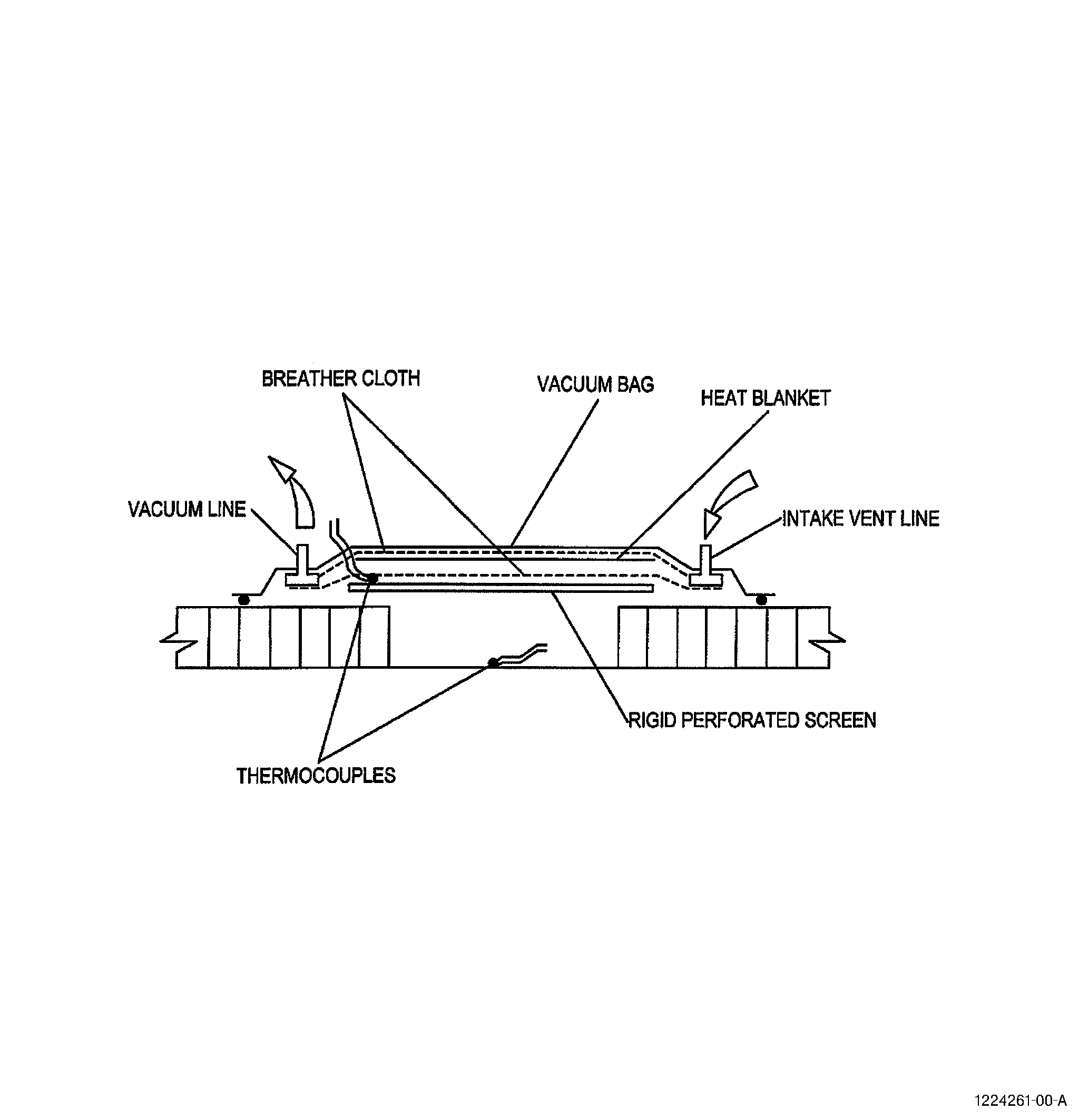
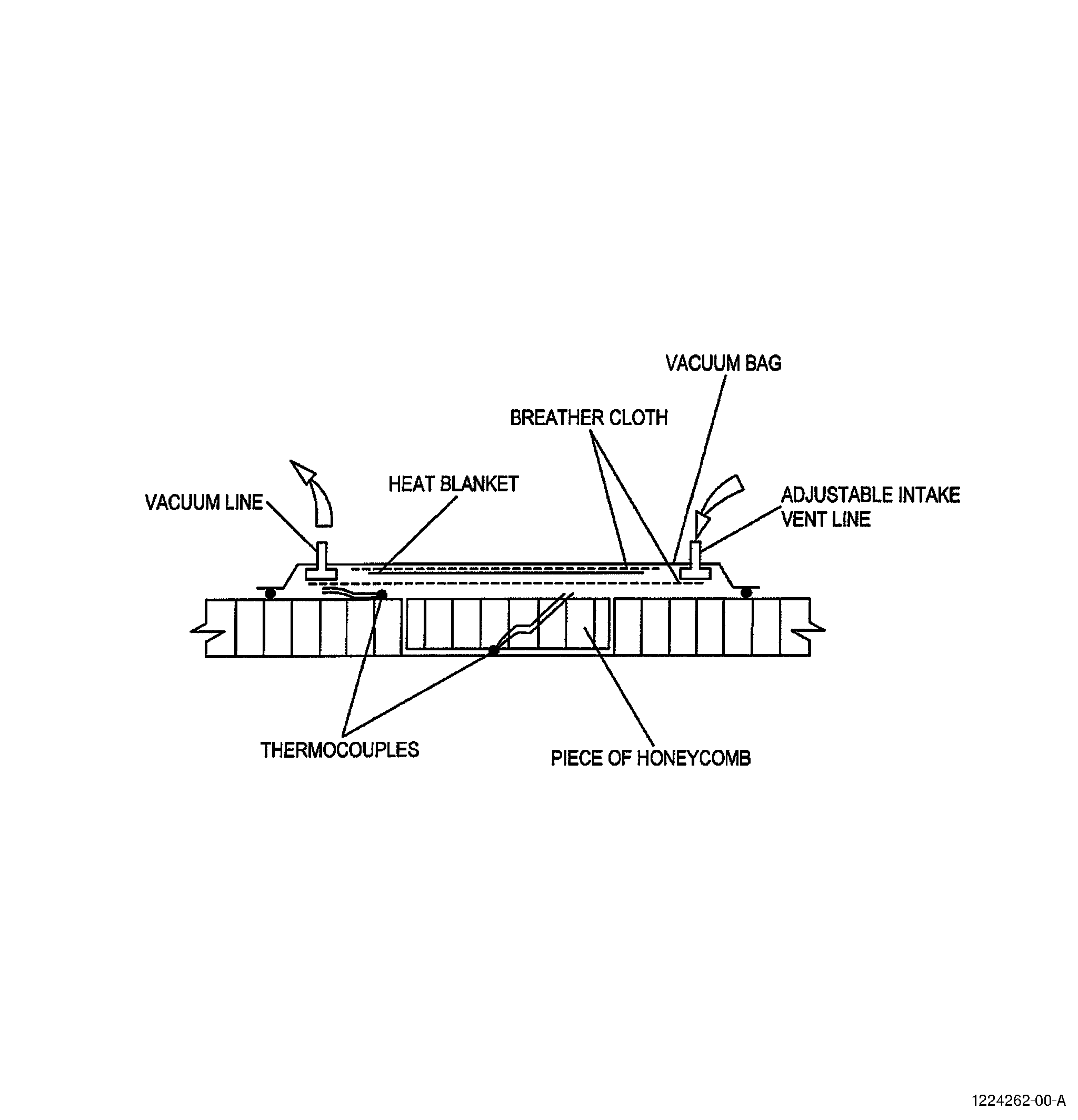
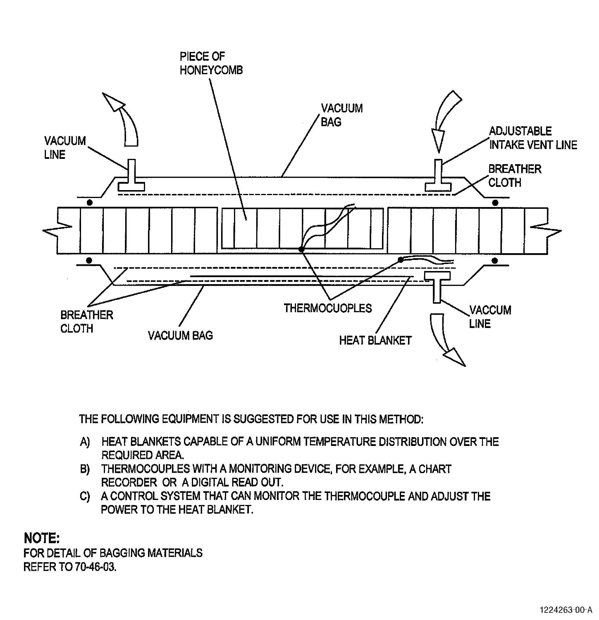
| C. | Absorbed Moisture Removal - Method 1 (Vacuum Bag and Heat Blanket) |
| This method is usually used on honeycomb structures. If only one skin is damaged, only one vacuum bag is required. Refer to Figure 3 (Sheets 1 and 2). If the damage penetrates both skins, a vacuum bag is required on both sides, or if the part is suitable it may be enclosed in an envelope bag. |
| A second vacuum bag can also be used to hold a heat blanket to the skin opposite the repair area. Application of heat to the skin opposite the repair area is preferred if it is possible. Refer to Figure 3 (Sheet 3). |
| (1) | Get the equipment for use in this method. Refer to C10-055 and as follows: |
| (a) | A heat blanket capable of a uniform temperature distribution over the required area. |
| (b) | Thermocouples with a monitoring device, for example, a chart recorder or a digital read out. |
| (c) | A control system that can monitor the thermocouples and adjust the power to the heat blanket. |
| CAUTION: |
|
| (2) | Make a vacuum bag as shown in Figure 3 and as follows: |
| (a) | Refer to TASK 70-46-03-360-003, Vacuum Bagging of Thermosetting Composite Repairs, to tell you how to make the bag. Refer to ARP5144 to tell you how to use a heating blanket. |
| (b) | Use a perforated metal plate to support the vacuum bag pressure on small damages only. Refer to Figure 3 (Sheet 1). A 4.0 inch (100 mm) wide damage will required a 0.16 inch (4 mm) thick aluminum perforated plate. |
| (c) | On large repairs where the honeycomb has been removed, use a piece of honeycomb inserted in the repair area to support the vacuum bag pressure. Refer to Figure 3 (Sheet 2 and 3). |
| (d) | If you have access to the opposite side, make a second vacuum bag to hold the heat blanket on the opposite side. Refer to Figure 3 (Sheet 3). |
| (e) | Put the intake vent line as far away from the vacuum line as you can. This is to get good air flow across the repair area. |
| CAUTION: |
|
| (3) | Apply the vacuum and adjust the intake vent line flow to maintain a vacuum of 12 inches (305 mm) of mercury. |
| (4) | If the time and temperature parameters are not in the repair document, refer to Step 3, Drying Parameters, for the parameters for your repair type. |
| (5) | Use the heat blanket control system to apply the vacuum and heat for the time specified. Monitor the thermocouples to make sure that the temperature is not greater than the specified temperature. |
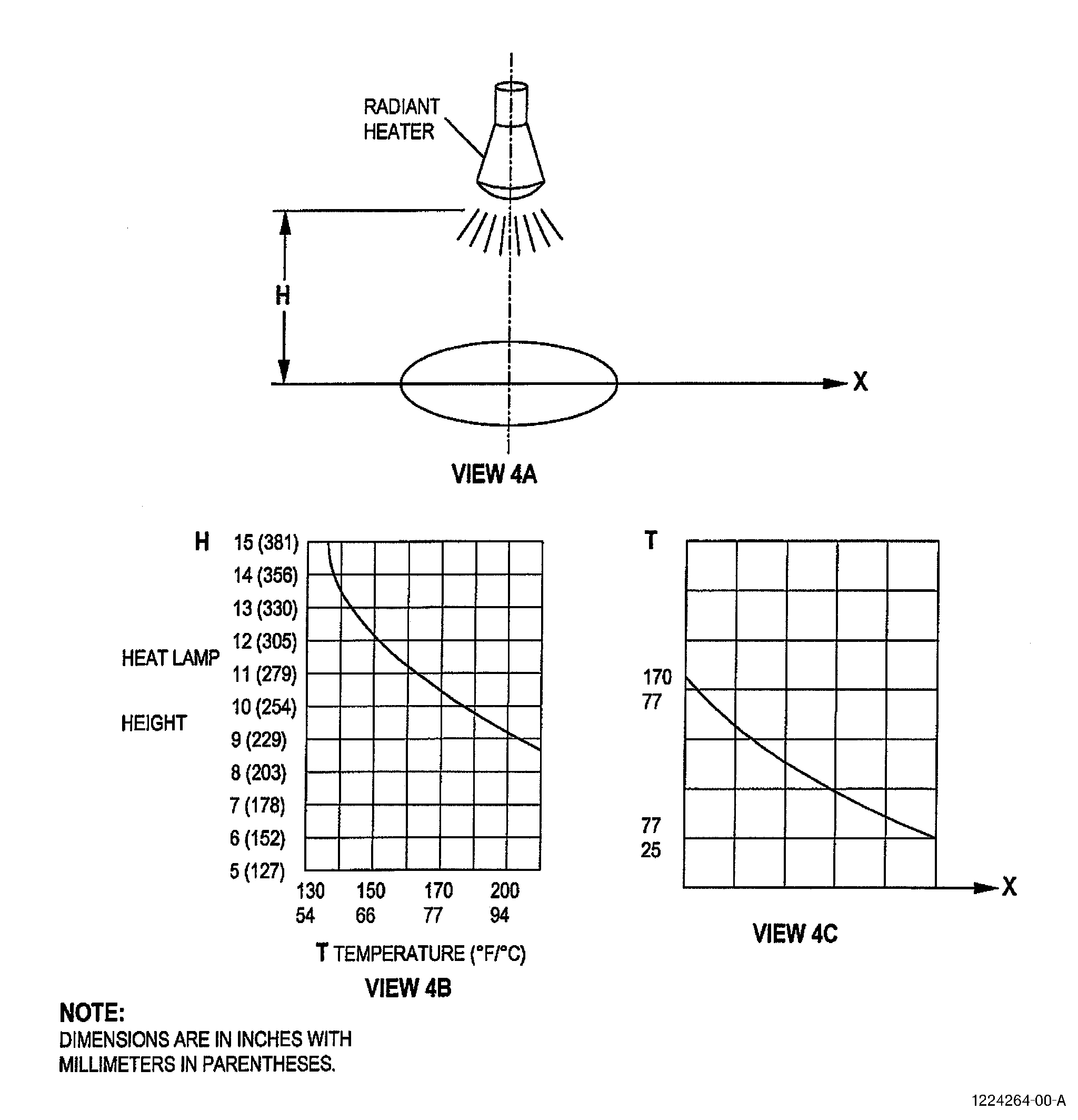
| D. | Absorbed Moisture Removal - Method 2 (Radiant Heater) |
| NOTE: |
|
| NOTE: |
|
| (1) | Get the equipment for use in this method. Refer to C10-055 and as follows: |
| (a) | Heat Lamp: 250W lamps are commonly used. |
| (b) | Radiator: 500 to 1000W coil elements with a reflector can be used. |
| (c) | Thermocouples with a monitoring device, for example, a chart recorder or a digital read out. |
| (d) | A control system can be used that can monitor the thermocouples and adjust the power to the heater. |
| NOTE: |
|
| (2) | Do a calibration of the heater as follows: |
| (a) | Make a graph similar to Figure 4 View 4B for the temperature at the center of the heated area as a function of the distance between the heater and the surface. |
| (b) | Use the graph to find the distance from the heater to the part for the specified temperature. |
| (c) | Make a second graph similar to Figure 4 View 4C for the temperature as a function of the distance from the center of the heated area at the distance chosen in Step 4.D.(2)(b). |
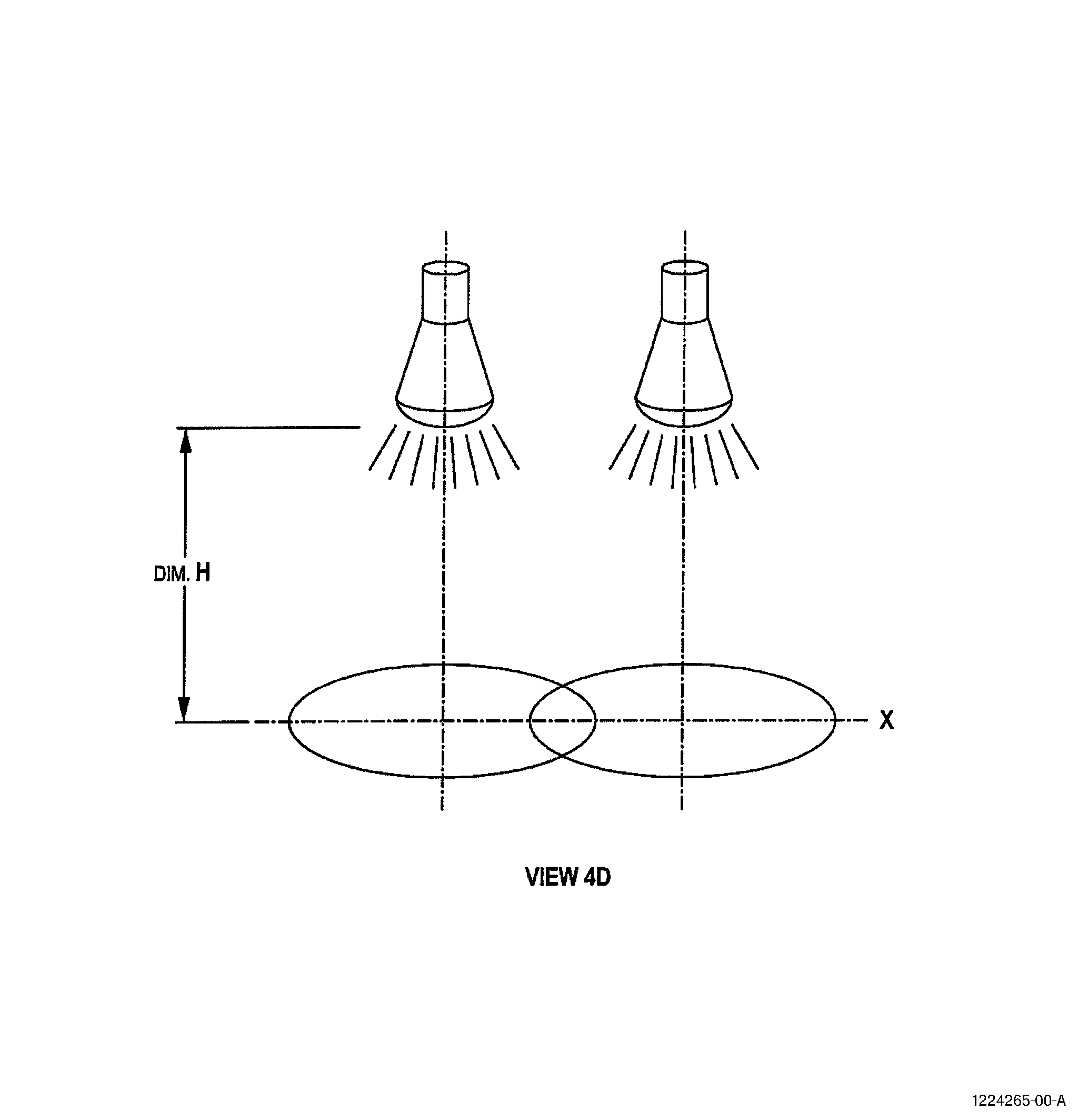
| (d) | If several heaters will be used, make the previous two graphs for the combined heaters similar to Figure 4 View 4D. |
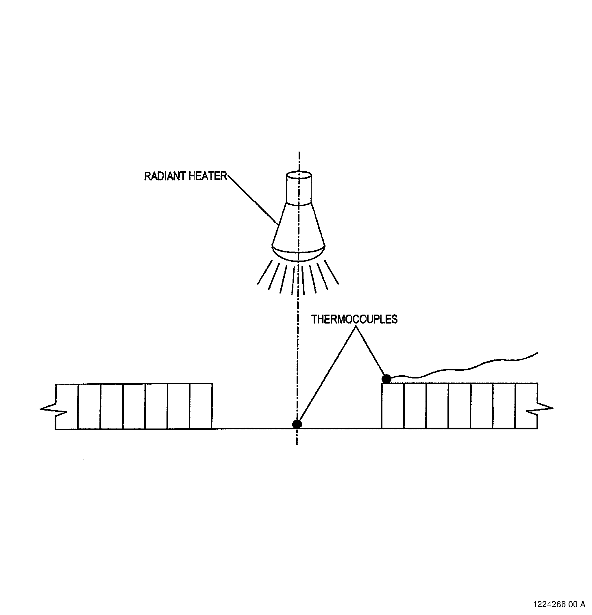
| (3) | Install the heaters. Refer to Figure 5 and as follows: |
| (a) | Install one or more heaters to get the specified temperature in the area to be dried. Use the calibration graph to get the distance. |
| (b) | Install thermocouples at the center of the heated area and at any positions where the specified temperature may be exceeded. Use the thermocouple at the center of the heated area for a heater control system, if available. |
| (4) | If the time and temperature parameters are not in the repair document, refer to Step 3, Drying Parameters, for the parameters for your repair type. |
| (5) | If available, use the control system to control the heat for the time specified. Monitor the thermocouples to make sure that the temperature is not greater than the specified temperature. |
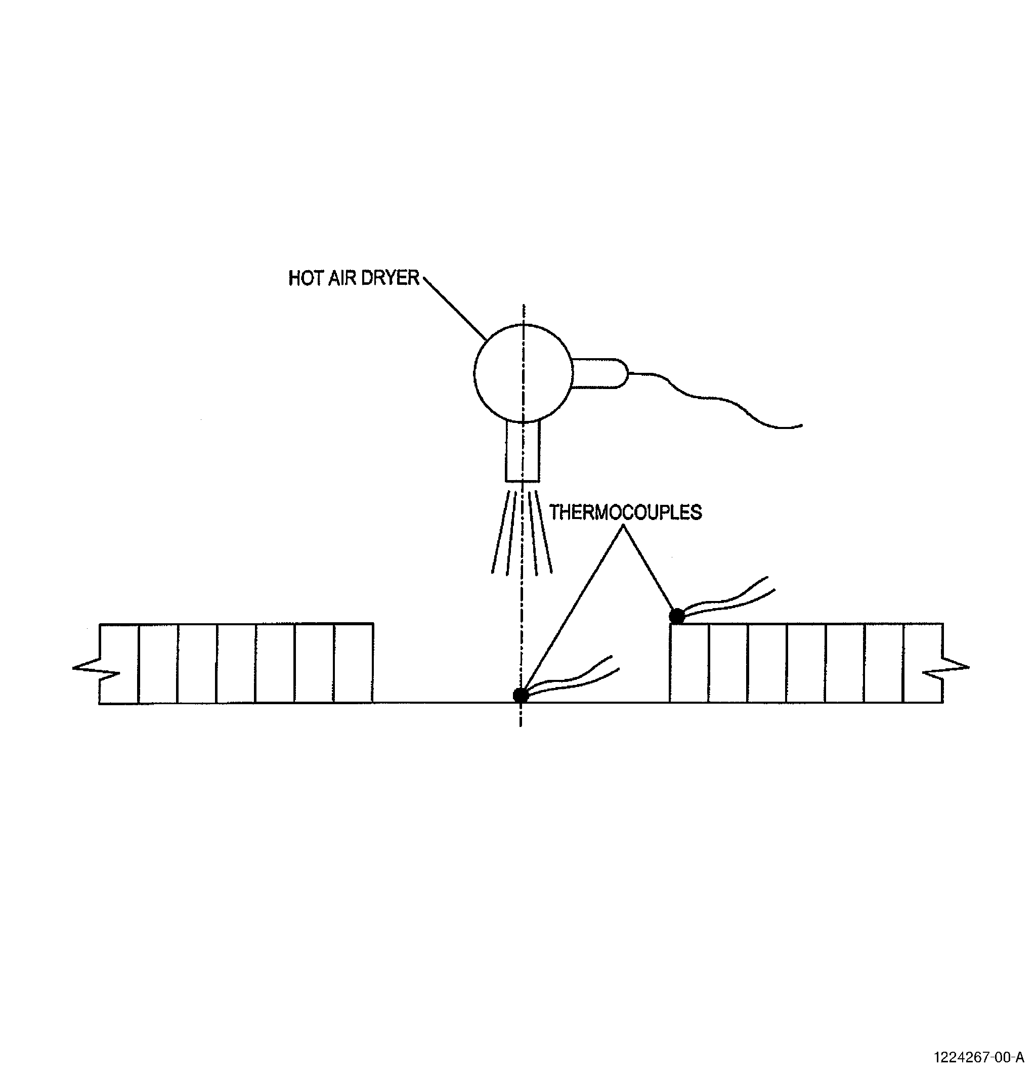
| E. | Absorbed Moisture Removal - Method 3 (Hot Air Dryer) |
| NOTE: |
|
| (1) | Get the equipment for use in this method. Refer to C10-054 and C10-055 and as follows: |
| (a) | Hot air dryer with variable temperature control are commonly used. |
| (b) | Thermocouples with a monitoring device, either a chart recorder or a digital read out. |
| (c) | A control system can be used that can monitor the thermocouples and adjust the power to the heater. |
| NOTE: |
|
| (2) | For calibration of the heat gun use the method described for heat lamps, refer to Absorbed Moisture Removal - Method 2 (Step 4.D.). |
| (3) | Install the heat gun, Refer to Figure 6 and as follows: |
| (a) | Install the heat gun to get the specified temperature in the area to be dried. Use the calibration graph to get the distance. If the heat gun has a variable temperature control, make sure that the control is at the same setting as that used to make the calibration graph. |
| (b) | Install thermocouples at the center of the heated area and at the other positions where the specified temperature may be exceeded. Use the thermocouple at the center of the heated area for a heat gun control system, if available. |
| (4) | If the time and temperature parameters are not in the repair document, refer to Step 3, Drying Parameters, for the parameters for your repair type. |
| (5) | If available, use the control system to control the heat for the time specified. Monitor the thermocouples to make sure that the temperature is not greater than the specified temperature. |
| F. | Absorbed Moisture Removal - Method 4 (Portable Oven) |
| NOTE: |
|
| NOTE: |
|
| (1) | Get the equipment for use in this method. Refer to C10-054 and Figure 7 and as follows: |
| (a) | Hot air dryer 1500 to 2000 W with adjustable temperature or equivalent hot air supply. |
| (b) | A control system can be used that can monitor the thermocouples and adjust the power to the heater. |
| NOTE: |
|
| (2) | Make a sheet metal oven for the area to be repaired. Refer to Figure 7. Use a hot air source with temperature adjustment. |
| (3) | Do a calibration of the oven to find any hot areas as follows: |
| (a) | Put the oven on a surface similar to the one to be dried and adjust the hot air dryer to give approximately the required temperature on the surface. |
| (b) | Make a map of the area covered by the oven that shows the surface temperatures. |
| (c) | Install the oven and the thermocouples for temperature monitoring and the heat control system, if available. Install the thermocouples in the hot areas previously found in Step 4.F.(3)(b). |
| (4) | If the time and temperature parameters are not in the repair document, refer to Step 3, Drying Parameters, for the parameters for your repair type. |
| (5) | If available, use the control system to control the heat for the time specified. Monitor the thermocouples to make sure that the temperature is not greater than the specified temperature. |
| G. | Absorbed Moisture - Method 5 (Oven) |
| NOTE: |
|
| (1) | Get the following equipment for use in this method: |
| (a) | An oven with an adjustable temperature from 120 to 180°F (49 to 82°C) and a temperature uniformity of plus or minus 9°F (5°C). The oven must be capable of running with a humid internal atmosphere without damage. |
| (2) | Put the part in the oven. Put the thermocouples in the area that you want to dry. |
| (3) | If the time and temperature parameters are not in the repair document, refer to Step 3, Drying Parameters, for the parameters for your repair type. |
| (4) | Use the oven control system to control the heat for the time specified. Monitor the thermocouples to make sure that the temperature is not greater than the specified temperature. |