| COMMERCIAL ENGINE STANDARD PRACTICES MANUAL | Dated: 10/01/2006 | |
| SPM 70-46-03 VACUUM BAGGING OF THERMOSETTING COMPOSITE REPAIRS | ||
| COMMERCIAL ENGINE STANDARD PRACTICES MANUAL | Dated: 10/01/2006 | |
| SPM 70-46-03 VACUUM BAGGING OF THERMOSETTING COMPOSITE REPAIRS | ||
| TASK 70-46-03-360-003 |
| 1 . | Introduction. |
| This Standard Practice is based on information contained in Aerospace Recommended Practice (ARP) 5143 and describes methods of vacuum bagging, a process used to apply pressure in adhesive bonding and heat curing of thermosetting epoxy and polyester matrix fabrications. |
| These methods must only be used when specified in the Engine/Shop Manual or in an approved repair document. |
| The vacuum bagging procedure is a part of the procedure for adhesive bonded and composite repairs. The bagging procedure refers to the sealing of the repaired area by enclosing it in an impervious plastic film. Air can then be removed from the bag to put pressure upon the materials of the repair. |
| For the vacuum bag cure, heat may be obtained with heat blankets, heat lamps, or by placing the assembly in an oven or autoclave. Refer to ARP5144. |
| 2 . | Materials and Installation Procedures for Bagging Operations. |
| This section describes the materials needed to carry out the different bagging steps and to describe the proper installation techniques, function, and potential problems of each of the vacuum bag materials. |
| In this Standard Practice it is assumed that the repair materials have already been applied. It is recommended that this section be referred to when following the instructions for proper installation using the methods of vacuum bagging in Step 6, Methods of Bagging. |
| All vacuum bag fabrics, films, and tapes need to be kept dry to prevent adding moisture to the repair. The storage environment needs to be non-contaminating, dust and oil-free. Protect materials from exhaust fumes, soot, oils, sprayed silicone, mist, rain, or other obvious particulate contaminates. If there is a risk of contamination, put the materials in a sealed bag or store in a closed, sealed container. |
| A. | Fabrics |
| NOTE: |
|
| (1) | Peel ply C10-131 |
| Peel ply is a layer of open-weave material, usually polyester or heat-set nylon, applied directly to the surface of an uncured lay-up. It protects the surface from contamination during subsequent procedures. It is preferable to leave the peel ply on until it is removed from the cured laminate immediately before further surface preparation, bonding or painting of the repair. |
| NOTE: |
|
| Dry peel ply can also be used as a light weight breather between the release film, heat blankets and caul plates. |
| Peel ply is available, pre-impregnated or dry. Refer to the repair document and ARP5319 for information on the use of peel ply with wet lay up repairs. |
| CAUTION: |
|
| (a) | Install peel ply as follows: |
| 1 | When you apply peel ply, remove all wrinkles. |
| 2 | If necessary on complex contours, cut and overlap the pieces of peel ply to prevent wrinkles. |
| (b) | Remove the peel ply as follows: |
| 1 | The peel ply will release easily from the repaired area after cure. |
| 2 | To remove peel ply, carefully lift one corner and pull the peel ply back over itself. |
| WARNING: |
|
| 3 | A sharp knife or a single edged razor blade may be used to lift the peel ply to begin removal. |
| 4 | Use caution to prevent damage to the composite plies below the peel ply. |
| (2) | Bleeder cloth C10-134 |
| NOTE: |
|
| Bleeder cloth is a woven fabric (for example a glass cloth C10-003) or non-woven mat C10-134. It is used in single or multiple layers that are put over the perforated release film to allow the passage of air or other gasses and to absorb resin squeezed from the laminate. It can also be put around the edge of the laminate or repair to provide an edge bleed. Some lay ups, especially prepreg, do not require bleed, and therefore do not use bleeder plies. |
| It is important to note that the number of bleeder plies, in combination with the selected bleeder cloth, peel ply, and/or perforated release film, will have a direct effect on the resin content of the cured component. Too few plies of bleeder cloth can result in a resin rich repair; too many plies of bleeder cloth can result in a resin starved repair. |
| There are two ways to bleed resin from a laminate: vertical and horizontal. Vertical bleed can be accomplished with the assembly bleeding through the top surface. Horizontal bleed is known as the Squeeze Out Method. If performing the Squeeze Out Method, edge bleeder is used to absorb excess resin. Refer to ARP5319 for more information. |
| (a) | Install the bleeder cloth C10-134 for edge bleed as follows: |
| 1 | Put a minimum of three narrow strips of bleeder cloth C10-134 around the edge of the lay up. |
| 2 | Overlap the strips of bleeder material approximately 1.5 inch (38 mm) to create a continuous border or window frame around the repair area. |
| NOTE: |
|
| (b) | Install the bleeder cloth C10-134 for vertical bleed as follows: |
| 1 | Put the bleeder cloth C10-134 smoothly over the assembly with as few wrinkles as possible and laid flat against the contour of the component. |
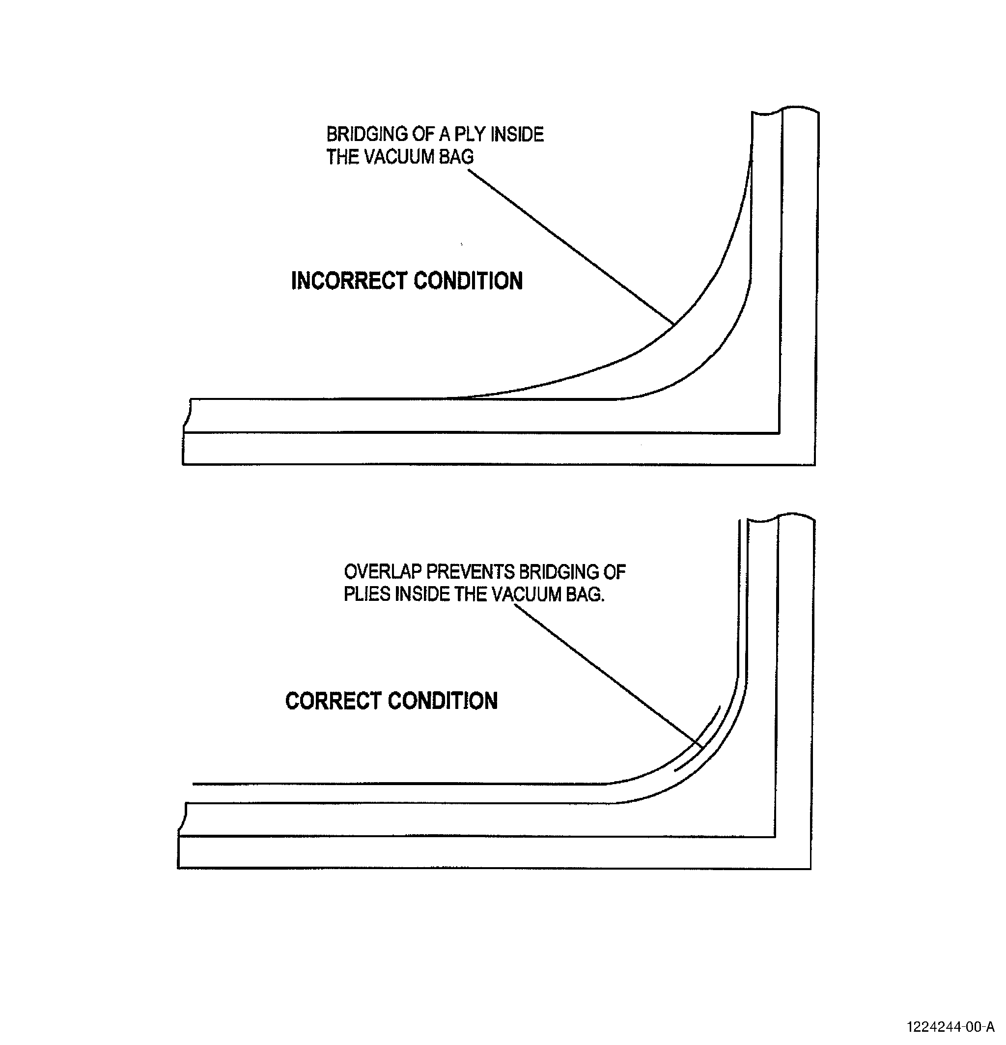
| 2 | If bridging is possible, splice the bleeder cloth to maintain full contact with the component. See Figure 1 and as follows: |
| a | Cut the cloth into two pieces and overlap approximately 0.5 inch (13 mm) minimum. |
| b | If the overlap is too small, movement can make a gap when vacuum is applied. This can interrupt the vacuum path. |
| c | Use small pieces of high temperature tape C10-040 or flashbreaker tape C10-136 to hold the overlapped edges together. |
| 3 | Use tape, if necessary, to hold the bleeder cloth in position. |
| 4 | Do not allow the tape to be under or over the vacuum bag sealant tape. |
| 5 | Do not allow the bleeder cloth to touch the vacuum bag sealant tape. Bleeder cloth fibers across the sealant tape can cause leaks. |
| (3) | Breather cloth C10-134 |
| NOTE: |
|
| Breather cloth is a woven fabric (for example a glass cloth C10-003 ) or non-woven mat C10-134. It is used in single or multiple layers that are put inside the vacuum bag to provide a continuous vacuum path to remove the air initially inside the bag. Breather cloth is also used to prevent resin from blocking vacuum ports, lines, valves, etc. |
| In unheated areas of the repair, sisal or polyamide nylon rope can be put around the periphery of the vacuum bag to provide a low air resistance ventilation channel to minimize vacuum drop across the vacuum bag. A ventilation channel is necessary in edge bleed vacuum bags to improve the resin bleed from the edge of the repair. |
| (a) | Install the breather cloth C10-134 as follows: |
| 1 | Cover all the area under the vacuum bag with breather cloth C10-134 to make sure there is a good vacuum path. |
| 2 | Put the breather cloth smoothly over the assembly with as few wrinkles as possible and laid flat against the contour of the component. |
| 3 | Put additional breather cloth C10-134 on all sharp areas where the vacuum bag can be punctured. |
| 4 | If necessary, put an open weave material around the periphery of the repair area. This is to make a good vacuum path |
| 5 | If bridging is possible, splice breather cloth to maintain full contact with the component. See Figure 1 and as follows: |
| a | Cut the cloth into two pieces and overlap a minimum of 1 inch (25 mm). |
| b | Be certain that the overlap is sufficient. If the overlap is too small, movement can make a gap when vacuum is applied. This can interrupt the vacuum path. |
| c | Use small pieces of high temperature tape C10-040 or flashbreaker tape C10-136 to hold the overlapped edges together. |
| 6 | Use tape, if necessary, to hold the breather cloth in position. |
| 7 | Do not allow the tape to be under or over the vacuum bag sealant tape. |
| 8 | Do not allow the breather cloth C10-134 to touch the vacuum bag sealant tape. Breather cloth fibers across the sealant tape can cause leaks. |
| (b) | Install breather cloth C10-134 as insulation as follows: |
| 1 | Alternative procedure available. Put the breather cloth C10-134 under the vacuum bag film over the heat blanket. |
| NOTE: |
|
| 1.A. | Alternative procedure. Put the breather cloth over the vacuum bag film and hold to the vacuum bag with high temperature tape C10-040 or flashbreaker tape C10-136. |
| 2 | Adjust the number of insulation plies for the ambient temperature and the required cure temperature. |
| B. | Films |
| NOTE: |
|
| (1) | Release Film |
| Release film is a permeable or impermeable layer of film that does not bond to the resin being cured. The most common films available are modified halohydrocarbons, PVF, coated fiberglass cloth (porous C10-178 and non-porous C10-179), polyester C10-142, and Fluorinated Ethylene Propylene (FEP), perforated C10-132 and unperforated C10-133. FEP films are used as release films for all types of epoxy resins and are light weight and easily conformable although the ability of the thinner films to stretch can make them difficult to apply to flat surfaces without wrinkles. |
| (a) | Perforated release film C10-132, also known as porous parting film or separator, is put between the repair plies (or peel ply, if used) and the bleeder cloth. This allows for gas flow and resin to bleed out through the film, and prevents the bleeder plies from bonding to the repair plies during the cure cycle. The kind of film selected (hole size and type of perforations, as well as perforation spacing) in combination with the choice of bleeder cloth has a direct effect on the resin content of the cured component. |
| (b) | Unperforated release film C10-133, also known as non-porous parting film or separator, is put over the bleeder plies to stop resin flow from bleeder plies into the breather cloth layers. It must be spliced or otherwise overlapped wide enough to prevent bleed-through of the resin or adhesive into the breather plies. Unperforated release film is also used as a barrier to stop excess resin from bleeding onto heat blankets and caul plates when they are used. |
| (c) | Install the release film as follows: |
| 1 | Put the film smoothly over the surface to maintain full contact with the surface of the repair plies during the cure cycle. |
| 2 | Use cuts and overlaps as necessary to prevent wrinkles, gaps or bridging at changes in shape in the assembly. Refer to Figure 1. |
| CAUTION: |
|
| 3 | Keep overlaps small and use small, narrow pieces of tape on the splices to cover less holes in the perforated release film. |
| (2) | Vacuum bag film C10-137 |
| Vacuum bag film is a plastic film that will not let air through, such as nylon or PVF. It is used to cover the repaired area or completely envelope the part (and the tool, if used). It is sealed at the edges so that vacuum can be applied. The vacuum bag film most typically used is 0.002 to 0.004 inches (0.05 to 0.10 mm) in thickness. Use of a thicker gauge of film helps to prevent punctures on complex shapes. Take care when you apply the vacuum bag film, avoid wrinkles as much as you can. Keep sharp-edged tools away from the vacuum bag film when they are not in use to prevent accidental cuts in the film. |
| Nylon vacuum bag film allows moisture from the air to be absorbed into the film. When the film is in a humid environment it is more flexible and is less likely to crack during bag fabrication. If brittle material is used the vacuum bag film may rip or tear. Ideal conditions are 50 to 70°F (10 to 21°C) and 40 to 60 percent relative humidity. |
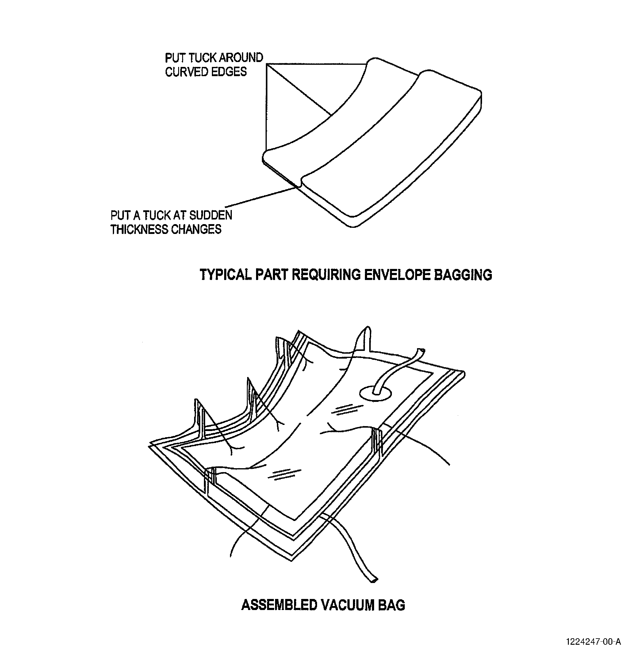
| (a) | There are different methods of making a bag over the repaired area. If the area to be repaired is small compared to the size of the part it is possible to seal only the area around the repair to the part surface this is known as a surface bag. Use an envelope bag (refer to Figure 2) or a bag that holds the part to a rigid tool in the following situations. Refer to Aerospace Information Report (AIR) 5431. |
| 1 | Large repairs. |
| 2 | Cures at the original cure temperature of the composite material. |
| 3 | Cures at the cure temperature of the adhesives on honeycomb sandwich parts. |
| 4 | Oven or autoclave cures. |
| Do not envelope bag hollow parts. This can cause crushing. Highly curved or flexible parts need a rigid support tool to maintain the part contour. Refer to AIR5431. |
| (b) | Install the vacuum bag film C10-137 . Refer to Figure 2, Figure 3, and Figure 4. |
| 1 | Cut the vacuum bag film C10-137 large enough to allow for movement under pressure and to allow for making tucks or pleats. Refer to Figure 3. |
| 2 | Use approximately 1.5 times the length and width of the area to be covered by the vacuum. |
| 3 | Put the vacuum bag sealant tape C10-138 around the repair area. Refer to Step 2.C.(1). |
| 4 | After you remove the paper backing from the vacuum bag sealant tape C10-138 , take care to position the vacuum bag film C10-137 evenly around the edge of the repair area. |
| 5 | Put the vacuum bag film C10-137 on the sealant tape with 1.0 to 2.0 inches (25 to 51 mm) overlap of vacuum bag film over the vacuum bag sealant tape C10-138 . |
| 6 | Seal the vacuum bag film at a minimum of four places equally spaced around the repair area. |
| 7 | Work from one side to the next making tucks and sealing the vacuum bag film C10-137 to the vacuum bag sealant tape. Put tucks at all sharp contour changes and on highly contoured parts to prevent bridging. Refer to Figure 4. |
| 8 | Make a tuck as follows: |
| a | Pull the vacuum bag film C10-137 from the vacuum bag sealant tape and put a piece of vacuum bag sealant tape C10-138 in the fold. |
| b | Push the vacuum bag film C10-137 firmly onto the vacuum bag sealant tape C10-138 to obtain an air-tight seal. |
| c | If the vacuum bag film C10-137 pulls on the sealant tape or bridges, the bag is too small or the tucks are not correctly positioned. |
| C. | Tapes |
| Some tapes have many uses both inside and outside of the vacuum bag. If you use the tape for a purpose other that described in this standard practice, check with the tape material manufacturer to make sure that the tape to be used is suitable for the application. |
| (1) | Vacuum bag sealant tape C10-138 |
| Vacuum bag sealant tape is a semi-cured plastic material with the tackiness to hold and seal the vacuum bag film during the cure cycle. It is supplied in rolls with one side covered with backing paper. Sealant tape is the sealing medium between the vacuum bag film and either the tool surface or the periphery of the repair area. Use the vacuum bag sealant tape designed for the temperature and pressure required or as called out by the repair document. Be aware of temperature limitations of some tapes. |
| (a) | Install the vacuum bag sealant tape C10-138 for a surface bag as follows: |
| 1 | Clean the surfaces where you will put the vacuum bag sealant tape. Refer to Composite Cleaning Methods 3, 4, or 5 in TASK 70-46-01-350-030, Masking and Cleaning of Epoxy and Polyester Matrix Thermosetting Composite Materials. |
| 2 | Put the vacuum bag sealant tape (C10-138), approximately 6 inches (152 mm) larger than the largest repair ply. |
| 3 | Apply the sealant tape in one continuous strip. Turn it at each corner and push it firmly with your thumb or the palm of your hand. |
| 4 | When you apply the sealant tape, be careful not to stretch the tape. This can cause the vacuum bag film to wrinkle when the tension is released. |
| 5 | Keep the paper backing on to prevent stretch in the sealant tape during application and to keep it clean from contaminants. |
| 6 | Do not remove the paper backing from the sealant tape until you are ready to apply the vacuum bag film. |
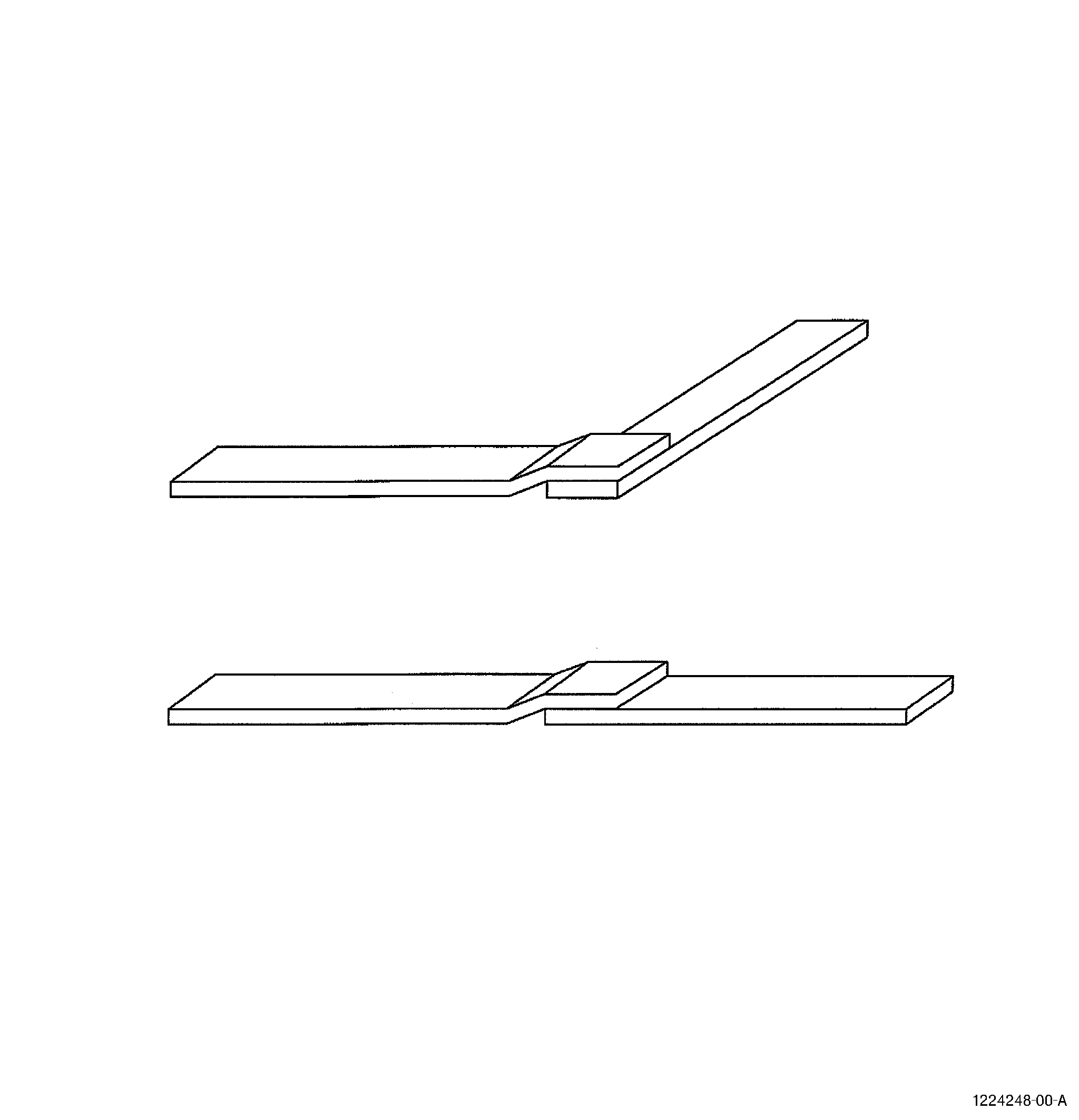
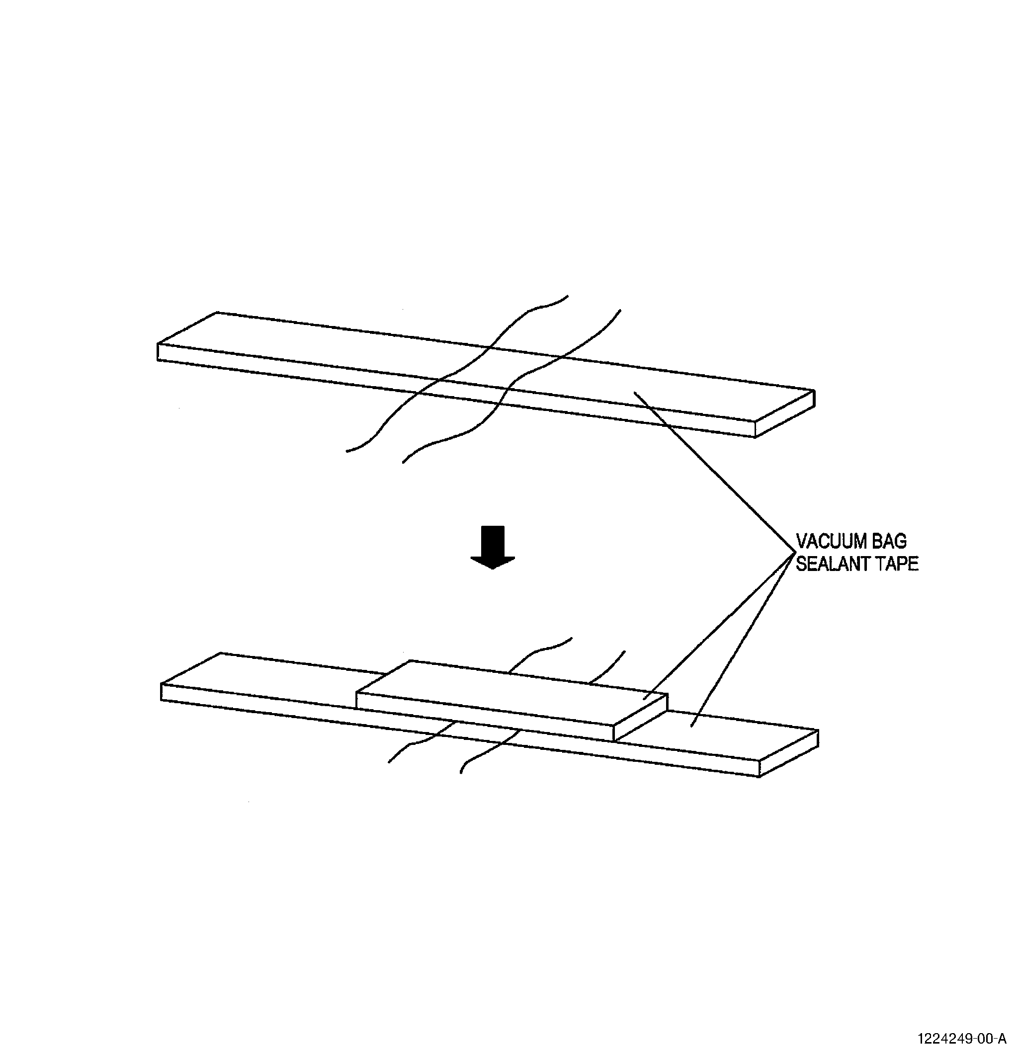
| 7 | Where sealant tape ends meet, the two strips should overlap. Refer to Figure 5. To do this, remove the paper from the sealant to be crossed and put the second strip over the sealant. |
| (b) | Install the vacuum bag sealant tape for an envelope bag as follows: |
| 1 | To make an envelope bag, apply the vacuum bag sealant tape around the periphery of the vacuum bag film approximately 2.0 inches (51 mm) from the edge of the film using the same method as described in Step 2.C.(1)(a) above. |
| 2 | When the bag is ready to be sealed fold the vacuum bag film around the part (and the tool, if used) to completely enclose the part. |
| 3 | Push the vacuum bag sealant tape together. Refer to Figure 2. |
| (2) | High temperature, pressure sensitive tape C10-040 or C10-136 |
| High temperature, pressure sensitive tape C10-040 or C10-136 is used for a variety of applications in the composite fabrication process. It will stick to another material when applied under finger pressure and it is capable of the temperatures during a high temperature cure. The tape is removed after the cure cycle is complete and is not part of the final composite assembly. The tape can be used, for example, to hold thermocouple wires and to hold the fabrics and films in position during assembly of the vacuum bag. |
| (a) | Flashbreaker tape C10-136 is nylon or polyester one sided, non-contaminating, adhesive coated, film tape. This is a tape used around the edge of a bonded joint or repair patch so that any adhesive that is squeezed out during cure can be easily removed. Refer to Composite Masking Method 5 in TASK 70-46-01-350-030, Masking and Cleaning of Epoxy and Polyester Matrix Thermosetting Composite Materials. |
| Flashbreaker tape C10-136 is also used for other applications in the composite repair process, for example to hold thermocouple wires around the repair area and to cover a caul plate to protect it from adhesive bleed out. |
| (b) | Double backed tape is a polyester film coated on both sides with a non-contaminating adhesive. It is used to hold items in position in vacuum bag lay-ups, for example to hold peel plies and breather cloths. |
| 3 . | Equipment and Installation Procedures for Bagging Operations. |
| This section describes the equipment needed to make different types of vacuum bags. This section describes equipment generically, in sufficient detail to allow a suitable commercial product to be purchased. It is not intended that the information provided be biased to any particular manufacturer and no commercial product is recommended in preference to any other. All equipment used should be capable of the temperatures at which cure is required. |
| This section also describes proper installation techniques, function and potential problems of vacuum bag equipment. It is assumed that the repair materials have already been applied. Refer to this section when you follow the instructions for installation described in the methods of vacuum bagging in Step 6, Method of Bagging. |
| A. | Thermocouples: |
| Thermocouples (also known as T/Cs) are used to monitor the cure temperature during the cure cycle. Several types of thermocouples can be found, but they always use the same principle: a device which uses a circuit of two wires of dissimilar metals or alloys, with dissimilar thermo-electric characteristics, joined at one end. Refer to ARP5144 for more detailed information. |
| Refer to the repair document and ARP5144 for the number of thermocouples required and their location, especially with regard to heat sinks and their effects. |
| (1) | Install the thermocouples. See Figure 6 and as follows: |
| (a) | Do a test of the thermocouples before you install them. Make sure that the thermocouples operate correctly. This is necessary to prevent repair of the bag because a thermocouple is not working correctly. Refer to ARP5144. |
| (b) | Put the wires through a seam in the vacuum bag sealant tape. Hold the wires to the base structure inside the bag with a pressure sensitive tape C10-136 . |
| (c) | Put the wires over the sealant tape C10-138 that is on the tool or part surface. |
| (d) | Cover the wires with a second piece of sealant tape C10-138 . |
| (e) | Keep the wires separated so that air cannot leak between the wires. |
| (f) | If necessary, seal the thermocouple wires to prevent vacuum leakage as follows: |
| 1 | If a thermocouple with a braided insulation is used, remove the braided insulation in the area where the wires go into the bag to prevent air leaks through the braid. |
| 2 | For other types of insulation, try to obtain the desired vacuum. If you find a leak around the wire, remove the exterior insulation locally. |
| NOTE: |
|
| (g) | Make sure that the wires do not cross any sharp corners or transitions that can damage the wires. |
| (h) | Do not let thermocouple wires cross each other when under the vacuum bag. This can cause inaccurate readings. Hold the wires with tape C10-040 or C10-136 . |
| B. | Caul plate |
| A caul plate is a smooth support plate, usually metal, cured composite or silicone sheet. Caul plates are used in the following ways: |
| (1) | To enhance the aerodynamics and aesthetic appearance by providing a smooth surface on the finished laminate. |
| (2) | To be a local tool to maintain contour possibly with the assembly tool to hold the part details in position. |
| (3) | To support the bag over an area where the vacuum bag pressure may cause local crushing at vulnerable edges. For example, at core splices or at repair edges when performing a drying operation on honeycomb parts. Refer to TASK 70-46-02-360-002, Drying of Thermosetting Composite Materials. In complex parts a caul plate may also be used during cure to support the bag over pockets or holes. |
| NOTE: |
|
| (4) | To provide more uniform temperature distribution when using a heat blanket, heat lamps or heat guns. A thin, flexible, metal sheet (the same size as the heat blanket, if one is used) can be used for even heat distribution to the repair area during cure. For more information on the use of caul plates for temperature distribution, refer to ARP5144. |
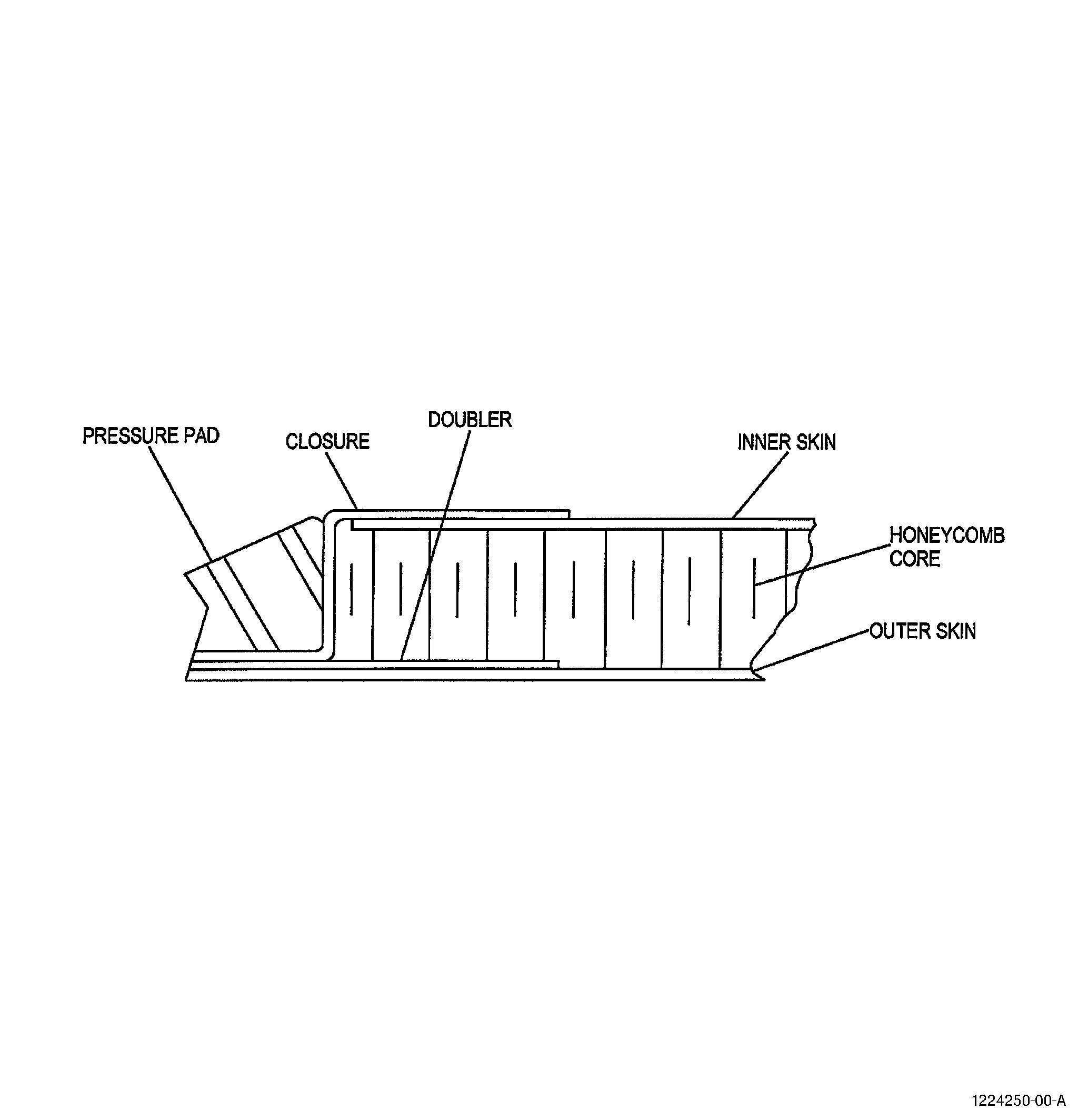
| C. | Pressure pad |
| Pressure pads, also somewhat inaccurately known as pressure intensifiers, are used to assure ply compaction in a specific location. They are generally made from felt or rubber. A pad may be used around square edges of honeycomb panels or to control the bondline thickness in a doubler area where a critical dimension is to be met. Pads may also be used on sharp edges or radii to prevent rupture of the vacuum bag film. |
| NOTE: |
|
| (1) | Install of pressure pads as follows: |
| (a) | Cover the pad with release agent C10-013 , flashbreaker tape C10-136 or release film C10-133 if the pad will touch uncured materials. |
| (b) | Cover the pad with breather material before you install the vacuum bag film C10-137 . |
| D. | Heat blankets C10-055 |
| Heat blankets are commonly made of a silicone rubber sheet with an electrical resistance heating circuit. They must be flexible to match the repair contour and have a good temperature uniformity to minimize hot and cold areas. Use caution when bending or forming heat blankets to prevent breaking the fragile wires in the blanket. Check with the heat blanket manufacturer for recommendations and/or limitations. |
| (1) | Install the heat blankets as follows: |
| (a) | Heat blankets have a cooler area around the perimeter of the blanket. Put the heat blanket so that it extends past the repair on all sides by a minimum of 2.0 inches (51 mm). Refer to ARP5144, Heat Application, for more information. |
| (b) | Put the heat blanket wires through a convenient area of the vacuum bag sealant tape C10-138 and away from any thermocouple wires. |
| (c) | Hold the wires to the base structure inside the bag with a pressure sensitive tape C10-040 or C10-136 . |
| (d) | Put the wires over the sealant tape C10-138 that is on the tool or part surface. |
| (e) | Cover the wires with a second piece of sealant tape. Refer to Figure 6. |
| E. | Vacuum ports |
| Vacuum ports provide air passage through the vacuum bag film and a connection for the vacuum pump and vacuum gauge or other vacuum monitor. A number of port designs are commercially available such as two piece ports or tube type ports. The two piece ports provide greater efficiency as there are fewer points of contact where a leak could occur. Tube type ports can be used when no space on the tool or repair periphery is available. |
| The vacuum port and the vacuum gauge port (refer to Step 3.F.) must be positioned at opposite corners of the bag where it is possible. At least one vacuum port and one vacuum gauge port are required. |
| (1) | Install a two piece vacuum port as follows. Refer to Figure 8. |
| (a) | Make a decision where the ports will be positioned. If possible, put the vacuum port and the vacuum gauge port near opposite corners of the bag. |
| (b) | Put the port away from the repair area. If no space is available around the repair, put the port in a tuck. Refer to Figure 8 (Sheet 2). This will prevent contact of the port with the repair area which can cause damage to the surface. |
| (c) | If the repair uses local heat application, put the port on an unheated area of the part and not on or near the edge of the heat blanket, if one is used. The concentration of heat in the metallic parts of the port can cause damage to the heat blanket C10-055 . |
| (d) | Where you will put the vacuum port, cut a hole in the vacuum bag film C10-137 with a circular hole punch or fold the film and cut a half circle, 1.0 inch (25 mm) diameter. |
| (e) | Put the vacuum bag film C10-137 over the vacuum connection and push firmly onto the gasket. If there is no gasket, make a gasket from vacuum bag sealant tape C10-138 . |
| (f) | Attach the outer ring of the fitting onto the stem of the port to clamp the vacuum port to vacuum bag film C10-137 . |
| (g) | Make a breather cloth pad from a piece of breather cloth C10-134 12 inches (294 mm) long and 12 inches (294 mm) wide. Fold the cloth into a 4.0 inch (102 mm) square, 9 ply thick pad. Make a breather cloth pad for each fitting. |
| (h) | Put the breather cloth pad inside the vacuum bag under the vacuum ports. This is to prevent obstruction of the air flow by the edges of the port and to absorb any resin flow before it gets into the vacuum line. |
| (i) | If the vacuum bag is large, use one vacuum port for every square meter. |
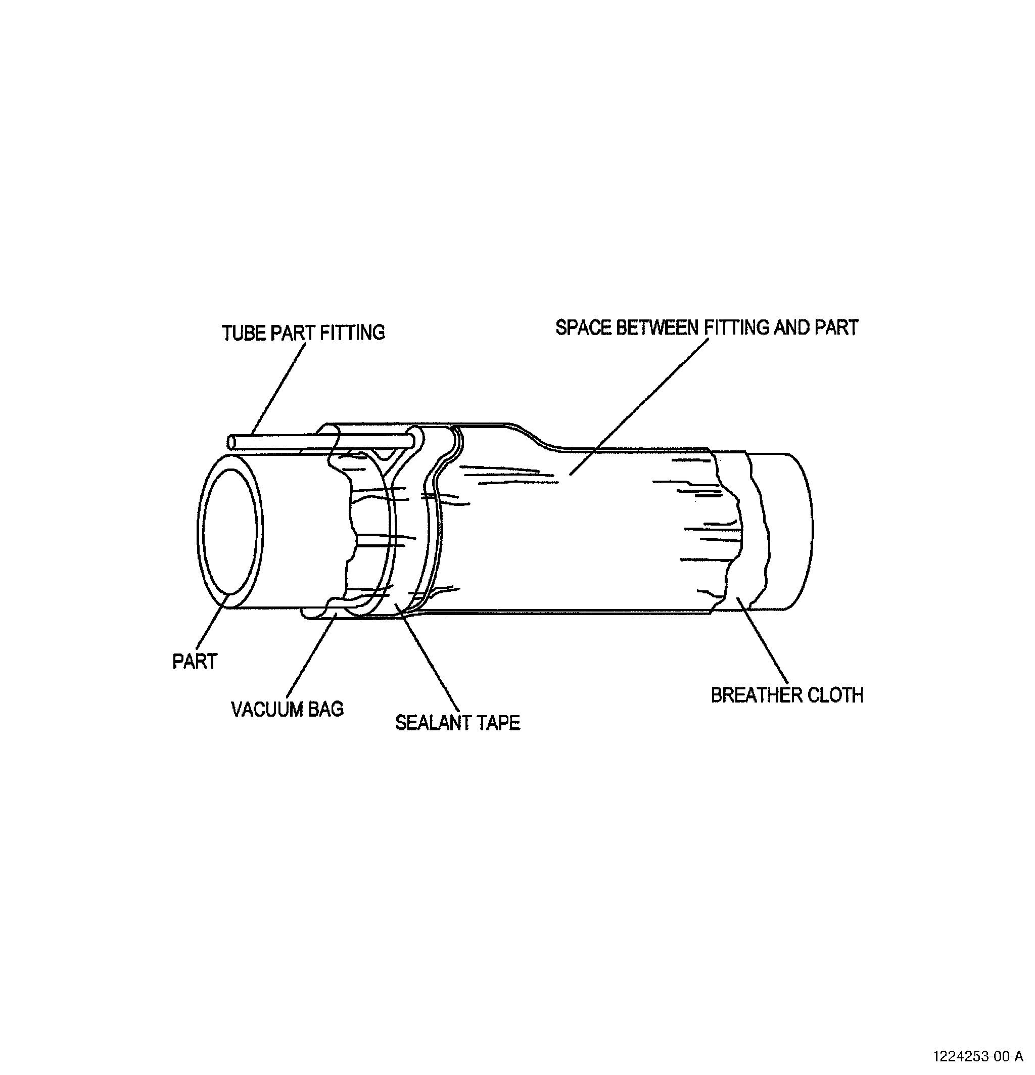
| (2) | Install the tube port. See Figure 8 (Sheet 3) and as follows: |
| (a) | Make or buy a length of tube with a vacuum line connection at one end and a series of perforations at the other. |
| (b) | Cover the perforated end of the tube with glass fabric C10-003 . Make the glass fabric C10-003 approximately 10 inches (254 mm) longer than the tube. |
| NOTE: |
|
| (c) | Make a decision where the port will be positioned. If possible put the vacuum port and the vacuum gauge port near opposite corners of the bag. |
| (d) | Put the port through a seam with the vacuum bag sealant tape around it. |
| (e) | Keep a space between the fitting and the part. The tube, when correctly installed, is in a tuck and does not touch the part. Refer to Figure 8 (Sheet 3). |
| (f) | Put the glass cloth C10-003 that is attached to the tube on the breather cloth C10-134 . |
| F. | Vacuum gauge ports |
| A vacuum gauge port is identical to a vacuum port, but is used to attach a vacuum gauge or a vacuum monitor line to measure the vacuum. You must have a minimum of one vacuum gauge port connection. If possible, put the connection at the opposite corner of the bag to the vacuum port. Refer to Step 3.E. |
| A vacuum gauge is a device attached directly to the vacuum gauge port capable of reading vacuum pressure. A negative vacuum pressure range of 0 to 30 inch Hg (0 to 100 kPa) is required. |
| A vacuum monitor line is a vacuum hose connected to the vacuum gauge port and to a remote vacuum monitoring device via permanent vacuum piping. This is usually used when curing parts in an oven or autoclave where it is not possible to read a gauge attached to the vacuum bag. |
| (1) | Install the vacuum gauge port. Refer to the vacuum port installation instructions in Step 4.E. |
| 4 . | Application of Vacuum Pressure and Leak Check. |
| The vacuum integrity check (leak test) is performed as the last step in the bagging process. It is important to make sure the bag is sealed properly and does not have leaks, before starting the cure. If the bag fails during the cure cycle, the vacuum bag will not be able to put equal pressure to the assembly. A failed bag can cause damage to the repair, this can cause you to have to do the repair again. |
| A. | Apply the vacuum pressure as follows: |
| (1) | When you have sealed the bag make the vacuum connections as follows: |
| (a) | Connect a vacuum gauge or vacuum monitor line to the vacuum gauge port. |
| (b) | Connect the vacuum port to the vacuum source. |
| (2) | Apply a vacuum of approximately 5 inch Hg (17 kPa). |
| (3) | Make sure that the bag is drawn into all contour changes, hollows and areas of overlays. |
| (4) | Make sure that no bridging occurs and adjust tucks as necessary. |
| B. | Do a check of the bag for leaks as follows: |
| (1) | Apply the minimum obtainable vacuum pressure available in the vacuum system, the vacuum must be a minimum of 22 inch Hg (75 kPa) unless otherwise specified in the repair document. |
| (2) | Keep the vacuum applied until the gauge value does not change. |
| (3) | Disconnect the vacuum source and measure the rate of vacuum loss (leak rate). |
| (4) | The leak rate must be less than 5 inch Hg (17 kPa) pressure drop timed for a 5 minute period. |
| (5) | If the leak rate is greater than this rate do the following steps to repair the leaks until the rate is less than the rate in Step 4.B.(4). |
| (a) | Look and listen for the leaks. The following are locations where leaks often occur. |
| NOTE: |
|
| 1 | Where the vacuum bag sealant tape has been doubled, for example, at thermocouple locations, heat blanket wire locations, tucks or joints |
| 2 | Vacuum port and vacuum gauge port locations (at locations where a hole is cut in the bag to accommodate the vacuum port fitting including vacuum line connections and fittings). |
| 3 | Where bleeder or breather material fibers are stuck to the vacuum bag sealant tape. |
| 4 | If the release film is over the sealant tape. |
| 5 | Pin holes in the vacuum bag film. |
| 6 | Vacuum bag sealant tape not secured to the part or surface especially if the surface is not properly cleaned or not fully cured from a previous stage of the repair. |
| 7 | Leaks between heat blanket wires, or thermocouple wires and insulation. |
| 8 | Leaks at part fastener locations that are under a surface bag. |
| 9 | Tool leaks associated with porosity and tool attachment points. Refer to AIR5431, Repair Tooling, for tool integrity checks and potential repairs. |
| (b) | Push the film more firmly into the sealant tape with a radius edged tool or your finger. |
| (c) | If you find a hole or tear in the vacuum bag film repair the hole as follows: |
| 1 | Cut a patch made from vacuum bag film larger than the hole or tear to be repaired by at least 2.0 inches (51 mm) in all directions. |
| 2 | Apply vacuum bag sealant tape to the patch and attach the patch over the leak. |
| 3 | Look at the patch. A correct patch will pull down as the air is removed from the patch. |
| NOTE: |
|
| 5 . | Repair Integrity and Evaluation Guidelines. |
| After the cure cycle has begun and a drop in vacuum is found, there are many factors to consider to make a decision on how the repair quality will be affected: |
| - Where the leak occurred. |
| - The amount of vacuum and how long it was not applied. |
| - The stage of the cure when the leak occurred. |
| If the loss of vacuum is on the edge seal of the bag and a channel breather or edge breather is being used, a leak is less likely to be detrimental. If the leak is coming through the back side of the repair or through the honeycomb and there is a possibility of the air going through the repair area, a problem is more likely in the repair. If the vacuum drops during a heat blanket cure, it will be easier to reseal the bag than if it is an oven cure where access is limited. |
| If the leak occurred before the resin was cured for up to 75 percent of the total required cure soak time, the quality of the repair may be degraded. Before a resin has reached 75 percent of its soak time, it may not be completely gelled. Use caution, since this may not apply to all resins. Once the resin has become gelled, it may be acceptable only if the heat source, such as a heat blanket, has not lifted away from the surface of the repair, resulting in uneven heat transfer. As a general rule, a loss of 5 inch Hg (17 kPa) may be acceptable for the rest of the cure, if more than that is lost, the quality of the repair may be compromised. |
| For repair integrity and evaluation guidelines for a power source or heat failure, refer to ARP5144. |
| These are guidelines only. The Engineering and Inspection Authority must evaluate these situations and determine further action. |
| 6 . | Methods of Bagging. |
| The methods provided are standard methods for the bagging of thermosetting composite materials that are referenced in repair documents. The methods must only be used when specified in an approved repair. |
| In the methods provided, all instructions are essential unless they are specifically stated as optional. Optional steps are added for specific repair needs. Optional steps should only be used if specified in the repair document. Read the methods carefully before you make the bag. Read all the optional procedures to make sure they apply. |
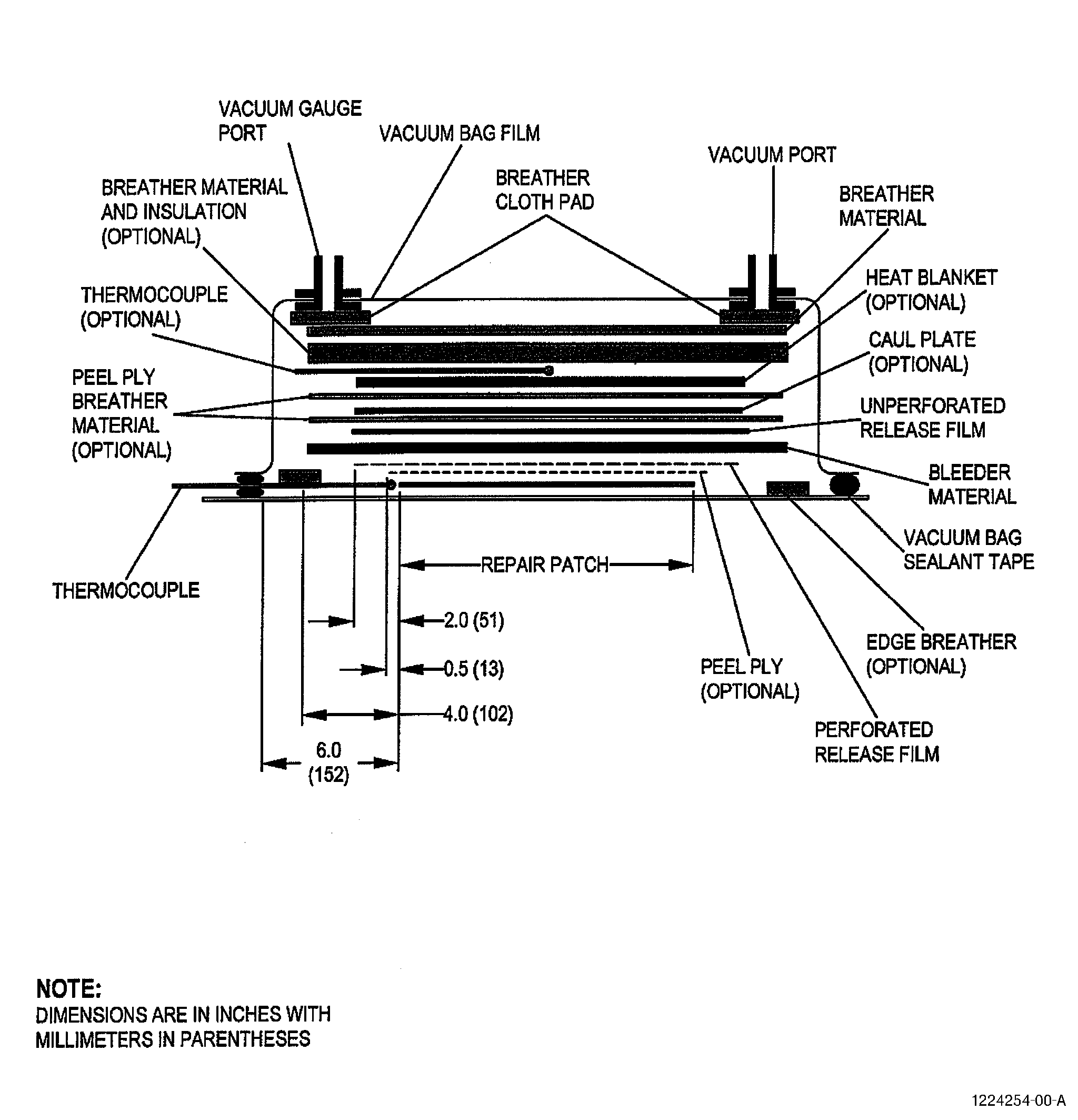
| A. | Method 1 - Vertical Bleed Cure with or without the use of a heat blanket. Refer to Figure 9. |
| Refer to the Installation Procedures, Step 2, Materials and Installing Procedures for Bagging Operations, thru Step 4, Application of Vacuum Pressure and Leak Check, for more detailed information on each step. |
| (1) | Apply flashbreaker tape C10-136 around the edge of the repair area. Refer to Composite Masking Method 5 in TASK 70-46-01-350-030, Masking and Cleaning of Epoxy and Polyester Matrix Thermosetting Composite Materials. |
| (2) | If peel ply is specified (optional), put a layer of peel ply C10-131 over the repair plies. Make the peel ply approximately 0.5 inch (13 mm) larger than the edge of the repair. Refer to ARP5319 for more information. |
| (3) | If edge breather is specified (optional), put a minimum of three strips of narrow breather material C10-134 approximately 4.0 inches (102 mm) from the edge of the largest repair ply around the repair. Keep 0.5 inches (13 mm) away from the peel ply. |
| (4) | Apply vacuum bag sealant tape C10-138 to the edge of the repair area, approximately 6.0 inches (152 mm) from the largest repair ply. Use Figure 9 as a guide to find the location of the vacuum bag sealant tape and the other materials inside the vacuum bag. Do not put the vacuum bag sealant tape on the flashbreaker tape. This can cause leaks. Do not remove the protective paper at this time. |
| (5) | Install the thermocouples. Refer to Step 3.A. and ARP5144. |
| (6) | Put a layer of perforated release film C10-132 over the repair area approximately 2.0 inches (51 mm) larger than the edge of the repair. Make the perforated release film smooth and remove wrinkles. |
| (7) | Put the bleeder material C10-134 over the perforated release film approximately 2.0 inches (51 mm) larger than the edge of the perforated release film. If you will use a heat blanket C10-055 , make sure the bleeder material will be a minimum of 2.0 inches (51 mm) larger than the edge of the heat blanket. Refer to the repair document for the number of bleeder plies. |
| (8) | Put a layer of unperforated release film C10-133 over the bleeder plies. Make the unperforated release film C10-133 2.0 inches (51 mm) smaller than the edge of the bleeder plies. |
| (9) | If a caul plate is specified in the repair document do the steps as follows (optional): |
| NOTE: |
|
| (a) | Put one layer of peel ply C10-131 over the unperforated release film C10-133 as a breather cloth layer under the caul plate. Make sure that the peel ply touches the bleeder plies along the edges. |
| (b) | Put the caul plate over the peel ply. |
| (10) | If a heat blanket is specified as the heat source (optional): |
| (a) | Put one layer of peel ply over the unperforated release film C10-133 (or the caul plate if one is used) as a breather cloth layer under the heat blanket. Make sure that the peel ply touches the bleeder plies along the edges. |
| NOTE: |
|
| (b) | Put the heat blanket on the peel ply. |
| (c) | If it is necessary to monitor the heat blanket to prevent a heat blanket temperature higher than allowed by the heat blanket specification then put a thermocouple over the center of the heat blanket. |
| (d) | Put two to three layers of breather cloth C10-134 over the heat blanket. This will also insulate the heat blanket and prevent damage to the vacuum bag film. Make sure that the breather cloth C10-134 touches the bleeder plies along the edges. |
| (11) | If a heat blanket is not specified, put one to two layers of breather cloth over the unperforated release film or the caul plate if specified. Make sure that the breather cloth makes contact with the bleeder plies along the edges. |
| (12) | Install the vacuum ports and cover the repair area with vacuum bag film C10-137 as follows: |
| (a) | Cut the vacuum bag film 1.5 times the size of the area to be covered. |
| (b) | Make a minimum of two openings in opposite corners of the vacuum bag film. One will be used for the vacuum port and one will be connected to the vacuum gauge port. |
| (c) | Seal the vacuum ports to the vacuum bag film. |
| (d) | Put the vacuum ports on the breather cloth pad, 4 plies thick minimum, and put them near the edge of the breather cloth layers. Do not put the vacuum ports on or near the repair area. If there is not sufficient area to put the vacuum ports next to the repair area, put the vacuum ports in a tuck. |
| (e) | Start to seal the vacuum bag as follows: |
| 1 | Remove the paper from the vacuum bag sealant tape adjacent to the vacuum port. |
| 2 | Lightly apply the film to the sealant tape. |
| 3 | Make sure that the vacuum bag film is not stretched and is in the correct position. Adjust if necessary. |
| 4 | Push the vacuum bag film firmly onto the vacuum bag sealant tape to make a seal. |
| (f) | Continue to remove the backing paper from the sealant tape and seal the edge of the vacuum bag to the sealant tape. |
| (g) | Put tucks in the vacuum bag film at intervals to allow for material stretch and contour changes. |
| (13) | Remove the air from the bag as follows: |
| (a) | Connect the vacuum source and slowly remove the air. Make the bag smooth with your hands as the air is removed. |
| (b) | Stop and make adjustments to the vacuum bag film C10-137 to prevent local stretch of the film. |
| (c) | Continue to remove the air from the vacuum bag. |
| (d) | Check the bag for leaks and seal it again if necessary. If available, use an ultrasonic leak detector to detect air leaks in the vacuum bag. A minimum vacuum pressure reading of 22 inch Hg (75 kPa) is required, unless otherwise specified by the repair document. |
| (e) | Wait for five minutes after the readings remain constant. |
| (f) | Disconnect the vacuum source at the probe and check the rate of vacuum loss. The leak rate should be less than 5 inch Hg (17 kPa) pressure drop, timed over a 5 minute period. |
| (g) | If the leak is larger than this rate, adjust the seal until it is satisfactory. |
| (14) | If you used a heat blanket and the rate of temperature increase is too slow, put breather cloth C10-134 as insulation material on the outside of the vacuum bag to make the heat loss slower. |
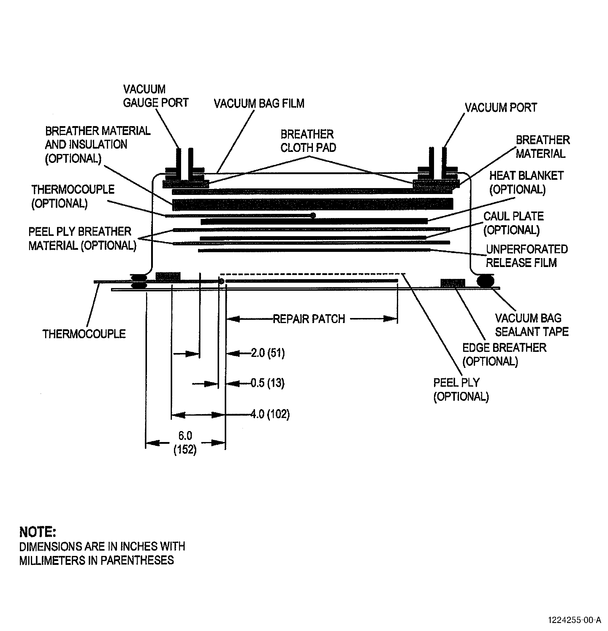
| B. | Method 2 - No Bleed Cure with or without the use of a heat blanket. Refer to Figure 10. |
| Refer to the Installation Procedures, Step 2, Materials and Installing Procedures for Bagging Operations, thru Step 4, Application of Vacuum Pressure and Leak Check, for more detailed information on each step. |
| (1) | Apply flashbreaker tape C10-136 around the edge of the repair area. Refer to Composite Masking Method 5 in TASK 70-46-01-350-030, Masking and Cleaning of Epoxy and Polyester Matrix Thermosetting Composite Materials. |
| (2) | If peel ply is specified (optional), put a layer of peel ply C10-131 over the repair plies. Make the peel ply approximately 0.5 inch (13 mm) larger than the edge of the repair. Refer to ARP5319 for more information. |
| (3) | If edge breather is specified (optional), put a minimum of three strips of narrow breather material C10-134 approximately 4.0 inches (102 mm) from the edge of the largest repair ply around the repair. Keep 0.5 inches (13 mm) away from the peel ply. |
| (4) | Apply vacuum bag sealant tape C10-138 to the edge of the repair area, approximately 6.0 inches (152 mm) from the largest repair ply. Use Figure 10 as a guide to find the location of the vacuum bag sealant tape and the other materials inside the vacuum bag. Do not put the vacuum bag sealant tape on the flashbreaker tape. This can cause leaks. Do not remove the protective paper at this time. |
| (5) | Install the thermocouples. Refer to Step 3.A. and ARP5144. |
| (6) | Put a layer of unperforated release film C10-133 over the repair area. Make the unperforated release film C10-133 approximately 2.0 inches (51 mm) larger than the edge of the repair. Make the release film smooth and remove wrinkles. |
| (7) | If a caul plate is specified in the repair document do the steps as follows (optional). |
| NOTE: |
|
| (a) | Put one layer of peel ply C10-131 over the unperforated release film C10-132 as a breather cloth layer under the caul plate. |
| (b) | Put the caul plate over the peel ply. |
| (8) | If a heat blanket is specified as the heat source: (optional) |
| (a) | Put one layer of peel ply over the unperforated release film C10-133 (or the caul plate if one is used) as a breather cloth layer under the heat blanket. |
| NOTE: |
|
| (b) | Put the heat blanket on the peel ply. |
| (c) | If it is necessary to monitor the heat blanket to prevent a heat blanket temperature higher than allowed by the heat blanket specification then put a thermocouple over the center of the heat blanket. |
| (d) | Put two to three layers of breather cloth C10-134 over the heat blanket. This will also insulate the heat blanket and prevent damage to the vacuum bag film. |
| (9) | If a heat blanket is not specified, put one to two layers of breather cloth over the unperforated release film or the caul plate if specified. |
| (10) | Install the vacuum ports and cover the repair area with vacuum bag film C10-137 as follows: |
| (a) | Cut the vacuum bag film 1.5 times the size of the area to be covered. |
| (b) | Make a minimum of two openings in opposite corners of the vacuum bag film. One will be used for the vacuum port and one will be connected to the vacuum gauge port. |
| (c) | Seal the vacuum ports to the vacuum bag film. |
| (d) | Put the vacuum ports on the breather cloth pad, 4 plies thick minimum, and put them near the edge of the breather cloth layers. Do not put the vacuum ports on or near the repair area. If there is not sufficient area to put the vacuum ports next to the repair area, put the vacuum ports in a tuck. |
| (e) | Start to seal the vacuum bag as follows: |
| 1 | Remove the paper from the vacuum bag sealant tape adjacent to the vacuum port. |
| 2 | Lightly apply the film to the sealant tape. |
| 3 | Make sure that the vacuum bag film is not stretched and is in the correct position. Adjust if necessary. |
| 4 | Push the vacuum bag film firmly onto the vacuum bag sealant tape to make a seal. |
| (f) | Continue to remove the backing paper from the sealant tape and seal the edge of the vacuum bag to the sealant tape. |
| (g) | Put tucks in the vacuum bag film at intervals to allow for material stretch and contour changes. |
| (11) | Remove the air from the bag as follows: |
| (a) | Connect the vacuum source and slowly remove the air. Make the bag smooth with your hands as the air is removed. |
| (b) | Stop and make adjustments to the vacuum bag film C10-137 to prevent local stretch of the film. |
| (c) | Continue to remove the air from the vacuum bag. |
| (d) | Check the bag for leaks and seal it again if necessary. If available, use an ultrasonic leak detector to detect air leaks in the vacuum bag. A minimum vacuum pressure reading of 22 inch Hg (75 kPa) is required, unless otherwise specified by the repair document. |
| (e) | Wait for five minutes after the readings remain constant. |
| (f) | Disconnect the vacuum source at the probe and check the rate of vacuum loss. The leak rate should be less than 5 inch Hg (17 kPa) pressure drop, timed over a 5 minute period. |
| (g) | If the leak is larger than this rate, adjust the seal until it is satisfactory. |
| (12) | If you used a heat blanket and the rate of temperature increase is too slow put breather cloth C10-134 as insulation material on the outside of the vacuum bag to make the heat loss slower. |
| C. | Method 3 - Squeeze Out Bleed Method. Refer to Figure 11. |
| Refer to the Installation Procedures, Step 2, Materials and Installing Procedures for Bagging Operations, thru Step 4, Application of Vacuum Pressure and Leak Check, for more detailed information on each step. |
| (1) | Apply flashbreaker tape C10-136 around the edge of the repair area. Refer to Composite Masking Method 5 in TASK 70-46-01-350-030, Masking and Cleaning of Epoxy and Polyester Matrix Thermosetting Composite Materials. |
| (2) | Put impregnated peel ply over outer laminate. Extend over the edge by 0.4 inches (10 mm). Refer to ARP5319 for more information. |
| (3) | Apply sisal or polyamide nylon rope around the repair area approximately 4.0 inches (102 mm) from the edge of the largest repair ply. |
| (4) | Put a minimum of three strips of narrow breather material C10-134 over the rope approximately 4.0 inches (102 mm) from the edge of the largest repair ply around the repair. Keep 0.5 inches (13 mm) away from the peel ply. Refer to Figure 11. |
| (5) | Apply vacuum bag sealant tape C10-138 to the edge of the repair area, approximately 6.0 inches (152 mm) from the largest repair ply. Use Figure 11 as a guide to find the location of the vacuum bag sealant tape and the other materials inside the vacuum bag. Do not put the vacuum bag sealant tape on the flashbreaker tape. This can cause leaks. Do not remove the protective paper at this time. |
| (6) | Install the thermocouples. Refer to Step 3.A. and ARP5144. |
| (7) | Install the vacuum ports and cover the repair area with vacuum bag film as follows: |
| (a) | Cut the vacuum bag film 1.5 times the size of the area to be covered. |
| (b) | Make a minimum of two cut openings in opposite corners of the vacuum bag film. One will be used for the vacuum port and one will be connected to the vacuum gauge port. |
| (c) | Seal the vacuum ports to the vacuum bag film. |
| (d) | Put the vacuum ports on a breather cloth pad, 4 plies thick minimum, and put them on the edge breather layers. Do not put the vacuum ports on or near the repair area. If there is not sufficient area to put the vacuum ports next to the repair area, put the vacuum ports in a tuck. |
| (e) | Start to seal the vacuum bag as follows: |
| 1 | Remove the paper from the vacuum bag sealant tape adjacent to the vacuum port. |
| 2 | Lightly apply the film to the sealant tape. |
| 3 | Make sure that the vacuum bag film is not stretched and is in the correct position. Adjust if necessary. |
| 4 | Push the vacuum bag film firmly onto the vacuum bag sealant tape to make a seal. |
| (f) | Continue to remove the backing paper from the sealant tape and seal the edge of the vacuum bag to the sealant tape. |
| (g) | Put tucks in the vacuum bag film at intervals to allow for material stretch and contour changes. |
| (h) | Do not put the tucks so that pleats are formed over the repair area. Try to make the vacuum bag smooth over the surface of the repair. |
| (8) | Remove the air from the bag as follows: |
| (a) | Connect the vacuum source and slowly remove the air. Make the vacuum bag smooth with your hands over the surface of the repair as the air is removed. |
| (b) | Stop and make adjustments to the vacuum bag film C10-137 to prevent local stretch of the film. |
| (c) | Continue to remove the air from the vacuum bag. |
| (d) | Check the bag for leaks and seal it again if necessary. If available, use an ultrasonic leak detector to detect air leaks in the vacuum bag. A minimum vacuum pressure reading of 22 inch Hg (75 kPa) is required, unless otherwise specified by the repair document. |
| (e) | Wait for five minutes after the readings remain constant. |
| (f) | Disconnect the vacuum source at the probe and check the rate of vacuum loss. The leak rate should be less than 5 inch Hg (17 kPa) pressure drop timed over a 5 minute period. |
| (g) | If the leak is larger than this rate, adjust the seal until it is acceptable. |
| (9) | Continue with the instructions of ARP5319, Impregnation of Dry Fabric and Ply Lay Up. |
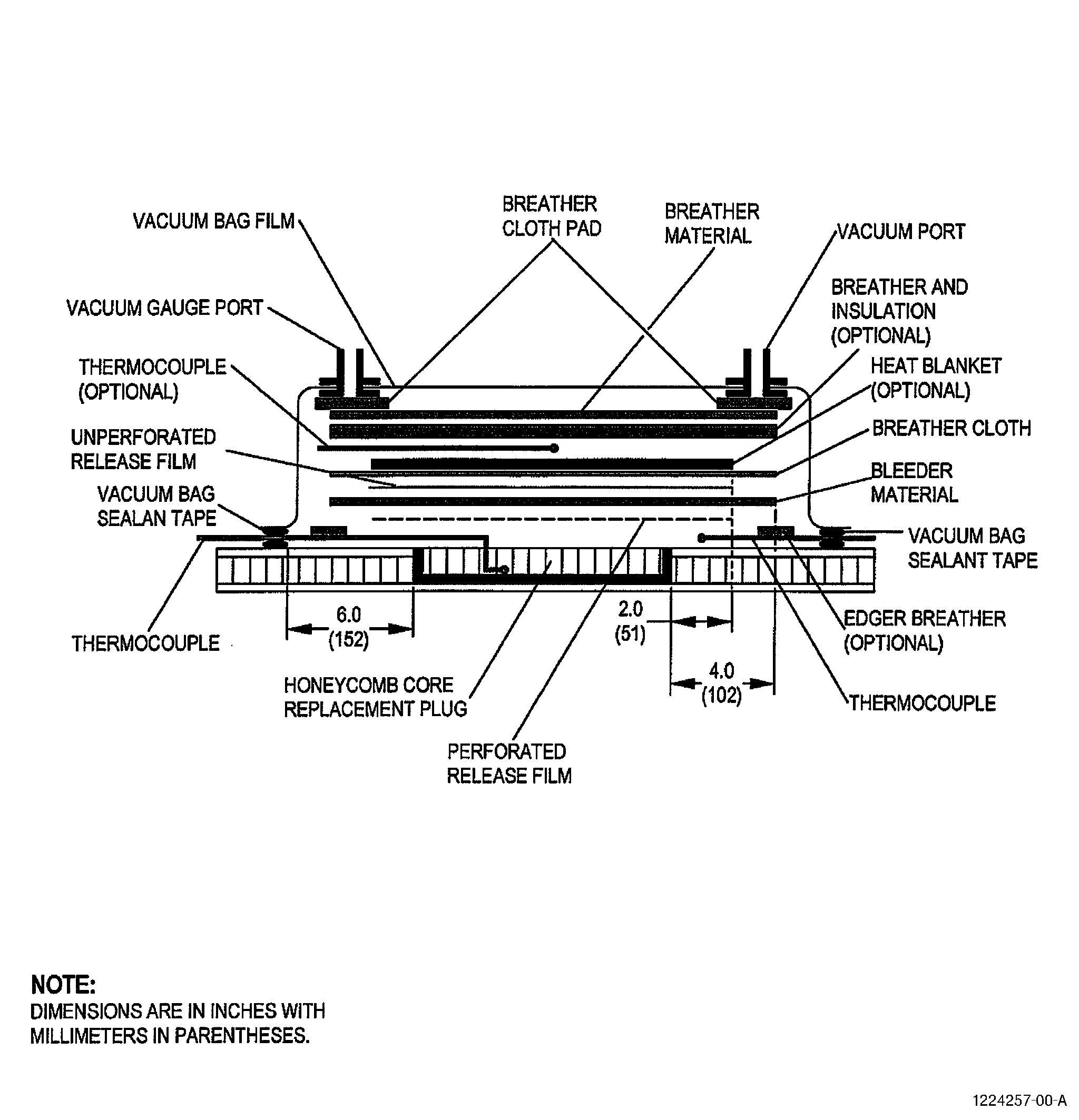
| D. | Method 4 - Core Restoration. Refer to Figure 12. |
| Refer to the General Installation Procedures in Steps 2. to 4. for more detailed information on each step. Follow ARP4991 Core Restoration for directions on how to prepare the core. For single sided heat application, refer to the repair document and ARP5144 for core plug thickness limits. |
| (1) | Apply flashbreaker tape C10-136 around the edge of the core replacement area. Refer to Composite Masking Method 5 in TASK 70-46-01-350-030, Masking and Cleaning of Epoxy and Polyester Matrix Thermosetting Composite Materials. |
| (2) | If edge breather is specified (optional), put a minimum of three strips of narrow breather material C10-134 approximately 4.0 inches (102 mm) from the edge of the core replacement area. |
| (3) | Apply vacuum bag sealant tape C10-138 to the edge of the repair area, approximately 6.0 inches (152 mm) from the largest repair ply. Use Figure 12 as a guide to find the location of the vacuum bag sealant tape and the other materials inside the vacuum bag. Do not put the vacuum bag sealant tape on the flashbreaker tape. This can cause leaks. Do not remove the protective paper at this time. |
| (4) | Install the thermocouples around the core replacement area and in the core. Refer to Step 3.A., ARP4991, and ARP5144 for more information. |
| (5) | Put a layer of perforated release film C10-132 over the core replacement area approximately 2.0 inches (51 mm) larger than the edge of the core replacement area. |
| (6) | Put the bleeder material C10-134 over the perforated release film approximately 2.0 inches (51 mm) larger than the edge of the perforated release film. If you will use a heat blanket C10-055 , make sure the bleeder material will be a minimum of 2.0 inches (51 mm) larger than the edge of the heat blanket. Refer to the repair document for the number of bleeder plies. |
| (7) | Put a layer of unperforated release film C10-133 over the bleeder plies. Make the unperforated release film C10-133 2.0 inches (51 mm) smaller than the edge of the bleeder plies. |
| (8) | If a heat blanket is specified as the heat source: (optional) |
| (a) | Put one layer of peel ply over the unperforated release film C10-133 as a breather cloth layer under the heat blanket. Make sure that the peel ply touches the bleeder plies along the edges. |
| NOTE: |
|
| (b) | Put the heat blanket on the peel ply. |
| (c) | If it is necessary to monitor the heat blanket to prevent a heat blanket temperature higher than allowed by the heat blanket specification then put a thermocouple over the center of the heat blanket. |
| (d) | Put two to three layers of breather cloth C10-134 over the heat blanket. This will also insulate the heat blanket and prevent damage to the vacuum bag film. Make sure that the breather cloth C10-134 touches the bleeder plies along the edges. |
| (9) | If a heat blanket is not specified, put one to two layers of breather cloth over the unperforated release film. Make sure that the breather cloth makes contact with the bleeder plies along the edges. |
| (10) | Install the vacuum ports and cover the core replacement area with vacuum bag film C10-137 as follows: |
| (a) | Cut the vacuum bag film 1.5 times the size of the area to be covered. |
| (b) | Make a minimum of two openings in opposite corners of the vacuum bag film. One will be used for the vacuum port and one will be connected to the vacuum gauge port. |
| (c) | Seal the vacuum ports to the vacuum bag film. |
| (d) | Put the vacuum ports on the breather cloth pad, 4 plies thick minimum, and put them near the edge of the breather cloth layers. Do not put the vacuum ports on or near the core replacement area. If there is not sufficient area to put the vacuum ports next to the core replacement area, put the vacuum ports in a tuck. |
| (e) | Start to seal the vacuum bag as follows: |
| 1 | Remove the paper from the vacuum bag sealant tape adjacent to the vacuum port. |
| 2 | Lightly apply the film to the sealant tape. |
| 3 | Make sure that the vacuum bag film is not stretched and is in the correct position. Adjust if necessary. |
| 4 | Push the vacuum bag film firmly onto the vacuum bag sealant tape to make a seal. |
| (f) | Continue to remove the backing paper from the sealant tape and seal the edge of the vacuum bag to the sealant tape. |
| (g) | Put tucks in the vacuum bag film at intervals to allow for material stretch and contour changes. |
| (11) | Remove the air from the bag as follows: |
| (a) | Connect the vacuum source and slowly remove the air. Make the bag smooth with your hands as the air is removed. |
| (b) | Stop and make adjustments to the vacuum bag film C10-137 to prevent local stretch of the film. |
| (c) | Continue to remove the air from the vacuum bag. |
| (d) | Check the bag for leaks and seal it again if necessary. If available, use an ultrasonic leak detector to detect air leaks in the vacuum bag. A minimum vacuum pressure reading of 22 inch Hg (75 kPa) is required, unless otherwise specified by the repair document. |
| (e) | Wait for five minutes after the readings remain constant. |
| (f) | Disconnect the vacuum source at the probe and check the rate of vacuum loss. The leak rate should be less than 5 inch Hg (17 kPa) pressure drop, timed over a 5 minute period. |
| (g) | If the leak is larger than this rate, adjust the seal until it is satisfactory. |
| (12) | If you used a heat blanket and the rate of temperature increase is too slow put breather cloth C10-134 as insulation material on the vacuum bag to make the heat loss slower. |
| (13) | If a heat blanket is specified and the back of the repair area is accessible, apply a heat blanket to the back of the repair. Do Steps 6.D.(3), (4), (8), (10), (11), and (12). |
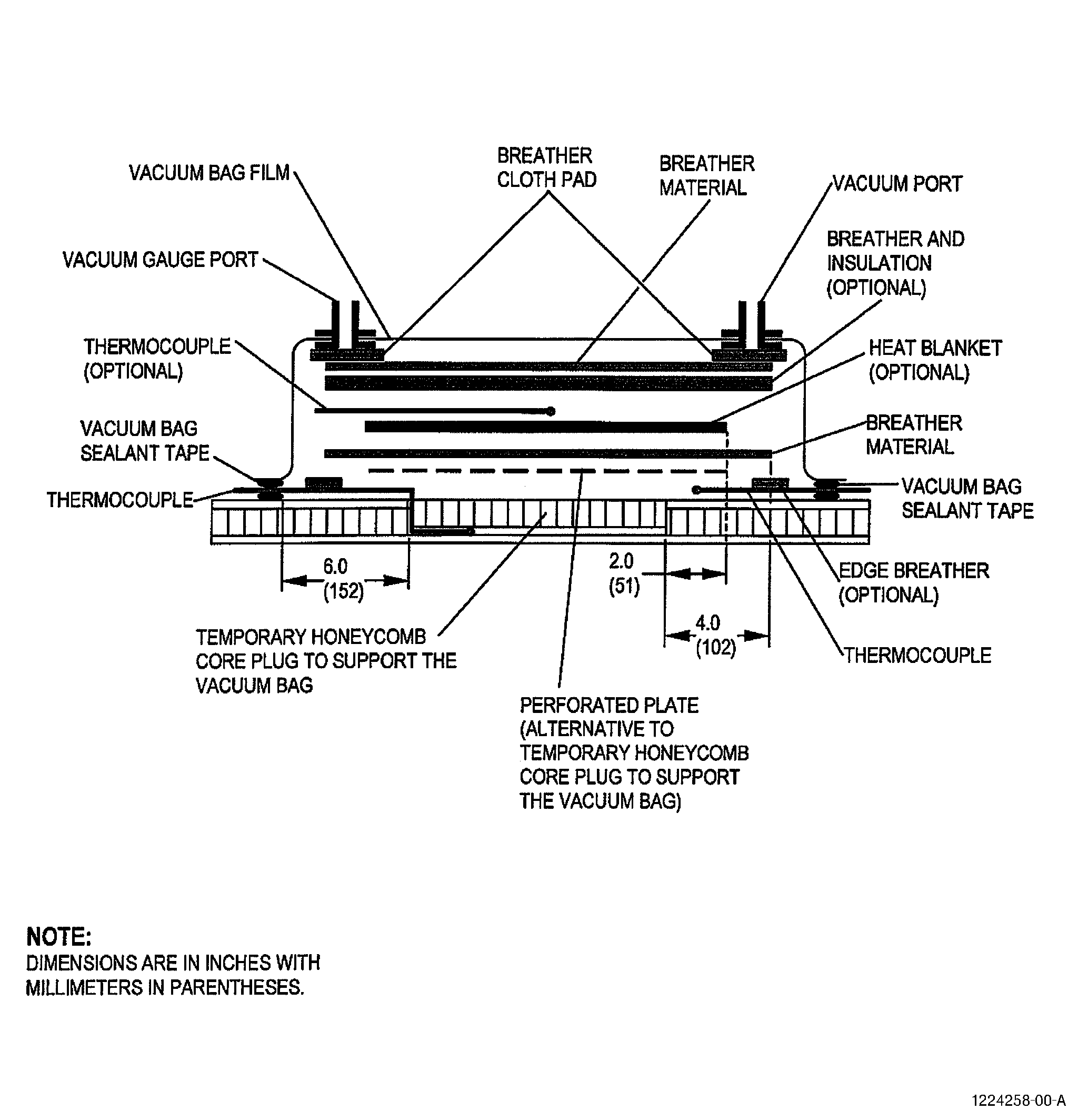
| E. | Method 5 - Drying Bag. Refer to Figure 13. |
| Refer to the Installation Procedures, Step 2, Materials and Installing Procedures for Bagging Operations, thru Step 4, Application of Vacuum Pressure and Leak Check, for more detailed information on each step. Refer to figure 3 in TASK 70-46-02-360-002, Drying of Thermosetting Composite Materials, for the alternative vacuum bag methods. |
| (1) | Apply the vacuum bag sealant tape C10-138 around the edge of the repair area. Use Figure 13 as a guide to find the location of the vacuum bag sealant tape and the other materials inside the vacuum bag. Do not remove the protective paper at this time. |
| (2) | Install a rigid perforated screen or temporary honeycomb core plug. Refer to the Absorbed Moisture Removal Method 1 in TASK 70-46-02-360-002, Drying of Thermosetting Composite Materials, for details and restrictions. |
| (3) | Install the thermocouples around the core replacement area and in the core. Refer to Step 3.A and ARP5144 for more information. |
| (4) | Apply one ply of breather material C10-134 over the perforated screen, or temporary honeycomb core plug, approximately 2.0 inches (51 mm) larger than the heat blanket. |
| NOTE: |
|
| (5) | If a heat blanket is specified as a heat source and is specified to be placed on the near side: (optional) |
| (a) | Put the heat blanket on the breather material. |
| (b) | If it is necessary to monitor the heat blanket to prevent a heat blanket temperature higher than allowed by the heat blanket specification then put a thermocouple over the center of the heat blanket. |
| (c) | Put two to three layers of breather cloth C10-134 over the heat blanket. This will also insulate the heat blanket and prevent damage to the vacuum bag film. |
| (6) | Install the vacuum ports and cover the repair area with vacuum bag film C10-137 as follows: |
| (a) | Cut the vacuum bag film 1.5 times the size of the area to be covered. |
| (b) | Make a minimum of two openings in opposite corners of the vacuum bag film. One will be used for the vacuum port and one will be connected to a port to let some air into the bag. Refer to the Absorbed Moisture Removal Method 1 in TASK 70-46-02-360-002, Drying of Thermosetting Composite Materials, for details. |
| (c) | Seal the vacuum ports to the vacuum bag film. |
| (d) | Put the vacuum ports on the breather cloth pad, 4 plies thick minimum, and put them near the edge of the breather cloth layers. Do not put the vacuum ports on or near the repair area. If there is not sufficient area to put the vacuum ports next to the repair area, put the vacuum ports in a tuck. |
| (e) | Start to seal the vacuum bag as follows: |
| 1 | Remove the paper from the vacuum bag sealant tape adjacent to the vacuum port. |
| 2 | Lightly apply the film to the sealant tape. |
| 3 | 3Make sure that the vacuum bag film is not stretched and is in the correct position. Adjust if necessary. |
| 4 | Push the vacuum bag film firmly onto the vacuum bag sealant tape to make a seal. |
| (f) | Continue to remove the backing paper from the sealant tape and seal the edge of the vacuum bag to the sealant tape. |
| (g) | Put tucks in the vacuum bag film at intervals to allow for material stretch and contour changes. |
| (7) | Remove the air from the bag as follows: |
| (a) | Connect the vacuum source and slowly remove the air. Make the bag smooth with your hands as the air is removed. |
| (b) | Stop and make adjustments to the vacuum bag film C10-137 to prevent local stretch of the film |
| (c) | Continue to remove the air from the vacuum bag. |
| (d) | Check the bag for leaks and seal it again if necessary. If available, use an ultrasonic leak detector to detect air leaks in the vacuum bag. A minimum vacuum pressure reading of 12 inch Hg (41 kPa) is required, unless otherwise specified by the repair document. |
| NOTE: |
|
| (8) | Open the port opposite the vacuum port to allow a controlled flow of air through the bag to assist the drying process. Make sure you keep a minimum vacuum of 12 inch Hg (41 kPa) in the bag. |
| (9) | If a heat blanket is specified (optional), you can add more insulating material over the vacuum bag to make the heat loss slower. |
| (10) | If a heat blanket is specified and the back of the repair area is accessible, apply a heat blanket to the back of the repair. Do Steps 6.E.(1), (3), (5), (6), (7) and (9). |