| GENX-1B CLEANING,INSPECTION,AND REPAIR MANUAL | Dated: 10/31/2022 | |
| CIR 72-00-52 , REPAIR 002 | ||
| HIGH PRESSURE TURBINE STAGE 2 NOZZLE ASSEMBLY - REPAIR - VANE SLEEVE REPLACEMENT FOR QUICK-TURN OR CONTINUED TIME SHOP VISITS | ||
| GENX-1B CLEANING,INSPECTION,AND REPAIR MANUAL | Dated: 10/31/2022 | |
| CIR 72-00-52 , REPAIR 002 | ||
| HIGH PRESSURE TURBINE STAGE 2 NOZZLE ASSEMBLY - REPAIR - VANE SLEEVE REPLACEMENT FOR QUICK-TURN OR CONTINUED TIME SHOP VISITS | ||
| * * * FOR ALL |
| TASK 72-00-52-300-802 |
| 1 . | Vane Sleeve Replacement for Quick-Turn or Continued Time Shop Visits. |
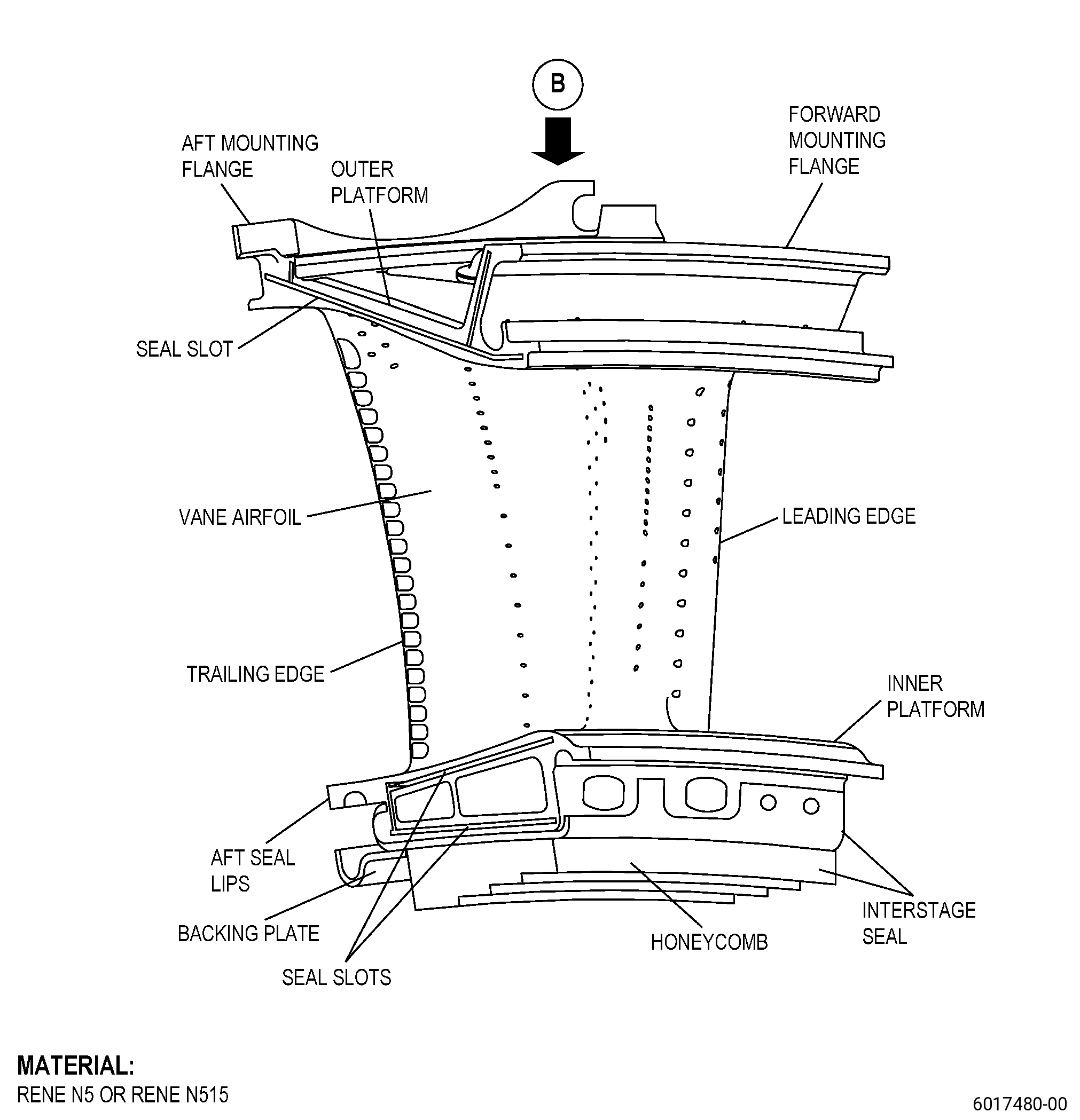
| A. | This procedure gives instructions to repair the high pressure turbine (HPT) stage 2 nozzle (nozzle) by removing the damaged vane sleeve and replacing it with a new vane sleeve. Refer to Figure 901. |
| B. | The following maximum repairable limits apply to this repair: |
| NOTE: |
|
| (3) | Visual Inspection. |
| (x) | Do an inspection of the nozzle segment sleeve collar. Refer to Figure 805. |
| 1 | Score marks, wear, or scratches on the ID: |
| Maximum repairable limit: |
|
| 2 | Braze cracks: |
| Maximum repairable limit: |
|
| 3 | Deformation: |
| Maximum repairable limit: |
|
| (y) | Do an inspection of the nozzle segment sleeve. Refer to Figure 805. |
| 1 | Cracks: |
| Maximum repairable limit: |
|
| 2 | Missing material or cracks opening: |
| Maximum repairable limit: |
|
| 3 | Nicks, dents, and gouges: |
| Maximum repairable limit: |
|
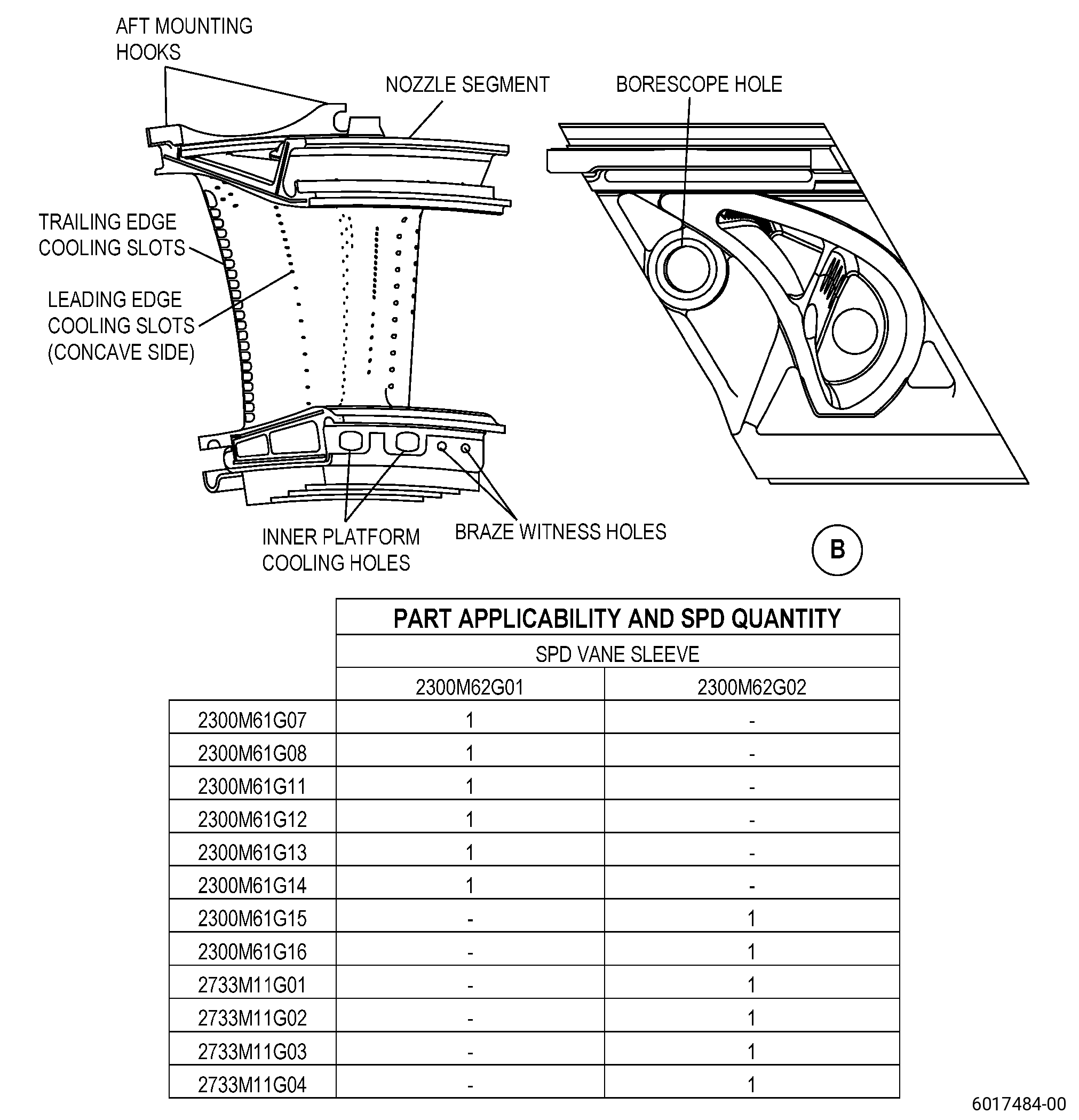
| C. | The subsequent table gives a list of the part numbers that are applicable to this procedure. All part numbers are applicable to all paragraphs unless specified differently. |
|
|||||||||||||||||||||||||||||||||||||||||||||||||
| D. | Proprietary/Complex Process Statement. |
| (1) | None. |
| 2 . | Tools, Equipment, and Materials. |
| NOTE: |
|
| A. | Tools and Equipment. |
| (1) | Special Tools. None. |
| (2) | Standard Tools and Equipment. None. |
| (3) | Locally Manufactured Tools. None. |
| B. | Consumable Materials. |
|
| C. | Referenced Procedures. |
|
| D. | Expendable Parts. None. |
| E. | SPD Information. |
| (1) | Spares Supplied. |
|
| (2) | Protected Spares. None. |
| (3) | Locally Manufactured Spares. None. |
| F. | Special Solutions. None. |
| G. | Test Specimens. None. |
| 3 . | Dimensional Information. |
| Subtask 72-00-52-220-098 |
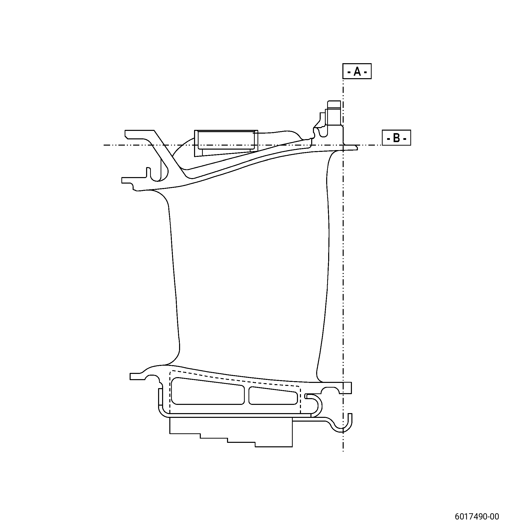
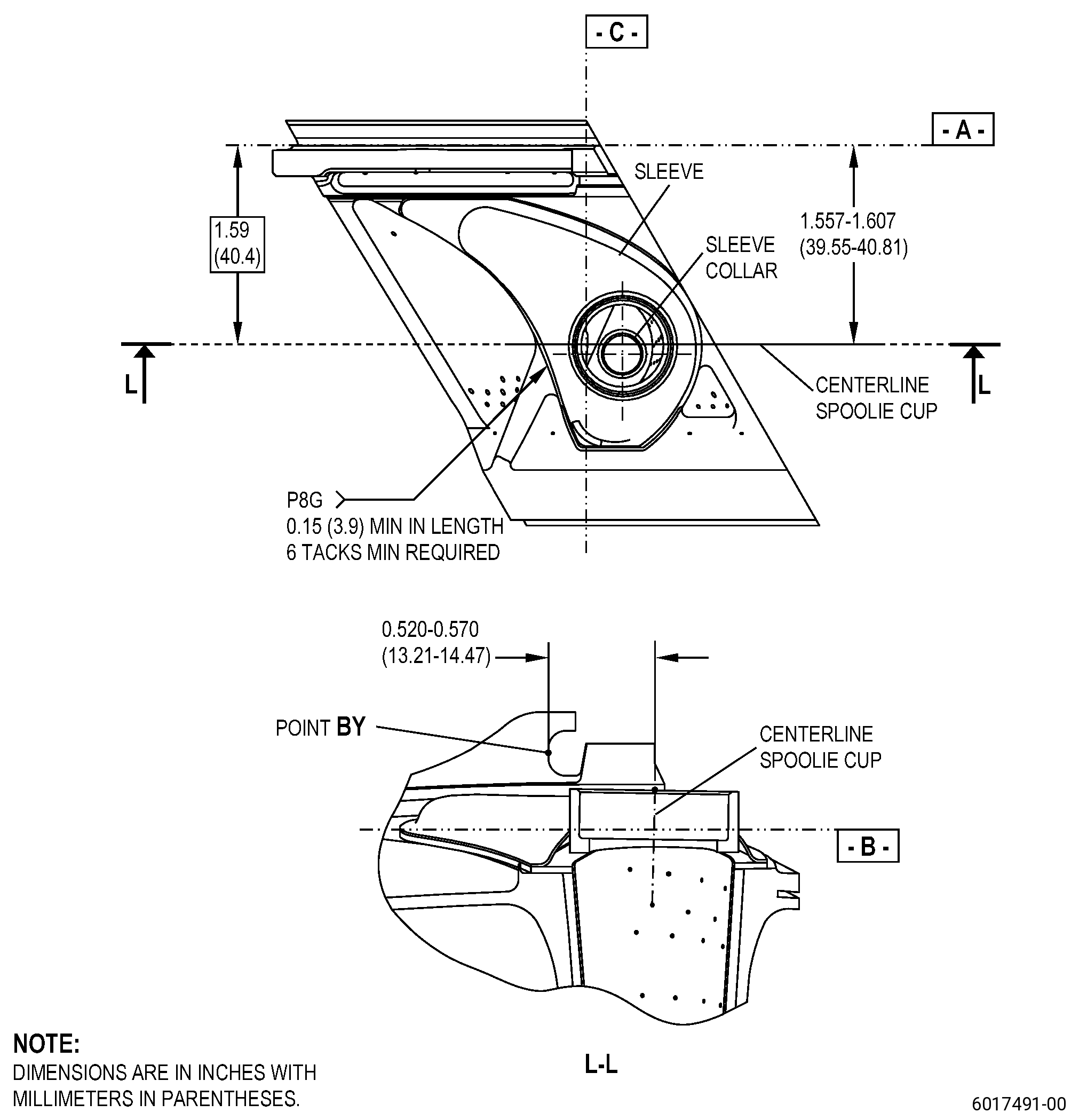
| A. | Refer to Figure 901 for specified dimensions and locations. |
| NOTE: |
|
| NOTE: |
|
| 4 . | Setup Information. |
| None. |
| 5 . | Procedure. |
| Subtask 72-00-52-350-001 |
| A. | Blend the nozzle tack welds to remove the vane sleeve from the nozzle. Refer to TASK 70-42-00-350-002 (BLENDING AND REMOVAL OF HIGH METAL PROCEDURES), Figure 901, and as follows: |
| (1) | Pull the vane sleeves out with pliers. |
| Subtask 72-00-52-350-002 |
| WARNING: |
|
| B. | Use dry shop air to remove unwanted material from the nozzle cavities. |
| Subtask 72-00-52-350-003 |
| C. | Install the new vane sleeve on the nozzle. Refer to paragraph 2.E., Figure 901, Figure 902, and as follows: |
| (1) | If necessary, blend to remove the aluminide coating from the tack weld areas of the nozzle. Refer to TASK 70-42-00-350-002 (BLENDING AND REMOVAL OF HIGH METAL PROCEDURES). |
| (2) | Install the new vane sleeve flange against the nozzle surface. |
| (3) | The maximum clearance permitted is 0.005 inch (0.12 mm) and as follows: |
| (a) | The average clearance permitted is 0.003 inch (0.07 mm) maximum. |
| Subtask 72-00-52-310-001 |
| (4) | Weld the vane sleeve to the nozzle with C06-051 L605 weld wire. Refer to TASK 70-41-00-310-001 (WELDING AND BRAZING PRACTICES) and as follows: |
| (a) | Blockage of the cooling holes because of welding is not permitted. |
| Subtask 72-00-52-220-099 |
| D. | Do an inspection of the nozzle. Refer to TASK 72-00-00-200-805 (72-00-00, INSPECTION 001). |