| COMMERCIAL ENGINE STANDARD PRACTICES MANUAL | Dated: 02/20/2018 | |
| SPM 70-41-00 WELDING AND BRAZING PRACTICES | ||
| COMMERCIAL ENGINE STANDARD PRACTICES MANUAL | Dated: 02/20/2018 | |
| SPM 70-41-00 WELDING AND BRAZING PRACTICES | ||
| TASK 70-41-00-310-001 |
| 1 . | General. |
| Repair welding is a safe, economical method to increase the service life of aircraft engine parts, when performed by qualified personnel using approved materials and techniques. The Engine/Shop Manuals for specific engines control the limits within which welding is an acceptable repair procedure, and designate the parts to which it can be applied. This section contains descriptions of the standard procedures to be used in repairing the various alloys used in those parts. (Refer to TASK 70-41-01-310-002, Titanium Welding Procedure, for special titanium welding procedure.) |
| 2 . | Policy. |
| Subtask 70-41-00-310-011 |
| A. | The primary factors to be considered in establishing repair welding procedures for any part include the following. |
| (1) | Risk. |
| Repair welds are generally prohibited on rotating components where any failure starting at a repair weld could result in an in-flight shutdown and/or severe damage to the engine. Refer to the Engine/Shop Manual for specific exceptions. |
| (2) | Risks with Base Metals and Filler Metals of Cobalt Alloys. |
| Care should be taken to avoid contact between copper fixtures or chill blocks to prevent liquid metal stress cracking when welding involves either cobalt alloy base metals or cobalt alloy filler metals. Copper fixtures and chill blocks should be protected with nickel plating, chrome plating, or flashing. As an alternative, you can use stainless steel gas backup cups or direct metal backup molybdenum sheets. |
| (3) | Susceptibility of an Alloy to Repair Welding. |
| While the alloys used in the engine require good control and care during repair welding, those parts designated in the Engine/Shop Manual can be safely and successfully repaired by the methods described in this section. |
| (4) | Welding Effect on Strength and Durability. |
| When establishing repair welding procedures, every effort is made to maintain the original load-carrying strength of the part. |
| (5) | Welding Effect on Dimensions. |
| One criterion of repair welding procedures is that parts must remain free of distortion. Several of the steps in this section are included for the purpose of maintaining dimensions within serviceable limits to avoid subsequent machining operations. |
| 3 . | Preparation for Welding. |
| WARNING: |
|
| Subtask 70-41-00-310-012 |
| A. | After inspection has disclosed repairable defects to be welded, the defects must be prepared for welding. |
| B. | Remove all paint, dirt, scale and carbon deposits from both front and back surfaces of the weld area, using a stainless steel rotary brush or 80-320 grit abrasive roll, disk or sheet. |
| C. | Remove all anodic or other chemical protective coating from front and back surfaces of aluminum parts within 0.50 inch (12.7 mm) of the weld area, using 160- or 180- grit abrasive roll, disk or sheet. |
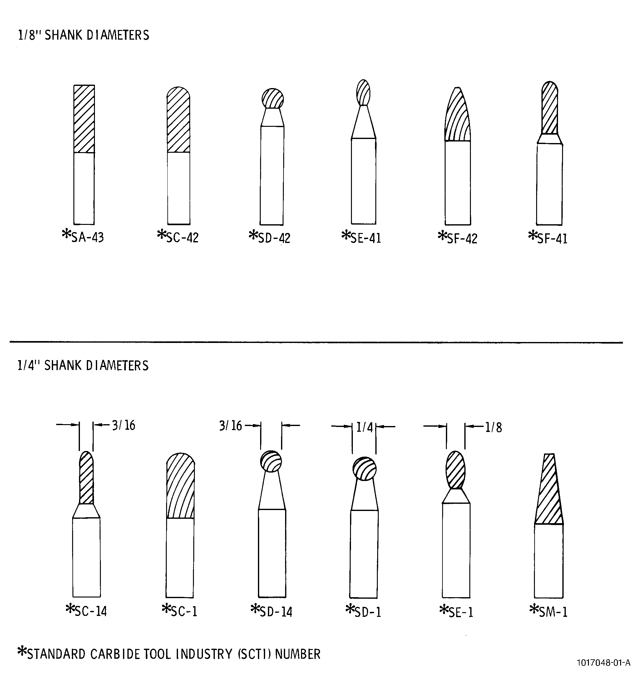
| D. | Standard carbide rotary files are available from the following distributors: Refer to Figure 6. |
| (1) | Arc Abrasives, refer to the List of Suppliers in Step 4 of 70-80-00. |
| (2) | A.T. McAvoy, refer to the List of Suppliers in Step 4 of 70-80-00. |
| (3) | Dixie Industrial Supply Company, refer to the List of Suppliers in Step 4 of 70-80-00. |
| (4) | Manson Tool and Supply, refer to the List of Suppliers in Step 4 of 70-80-00. |
| E. | Vitrified abrasive mounted points are available from the following sources: |
| (1) | Arc Abrasives, refer to the List of Suppliers in Step 4 of 70-80-00. |
| (2) | Norton Company, refer to the List of Suppliers in Step 4 of 70-80-00. |
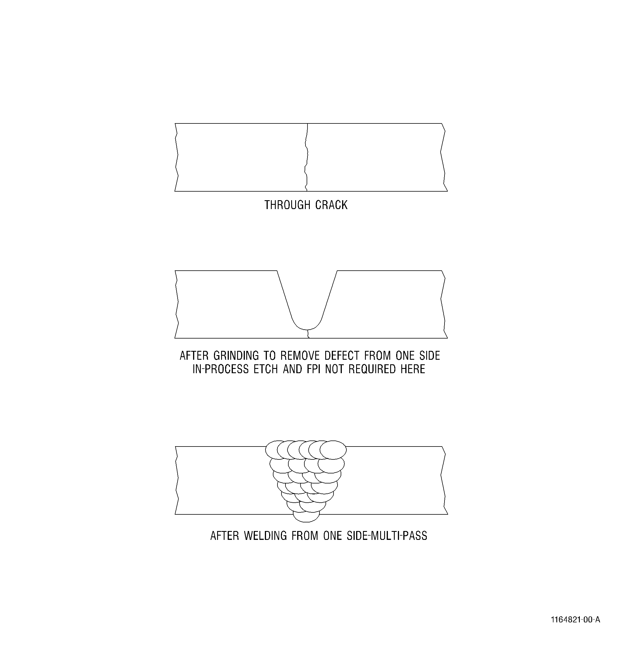
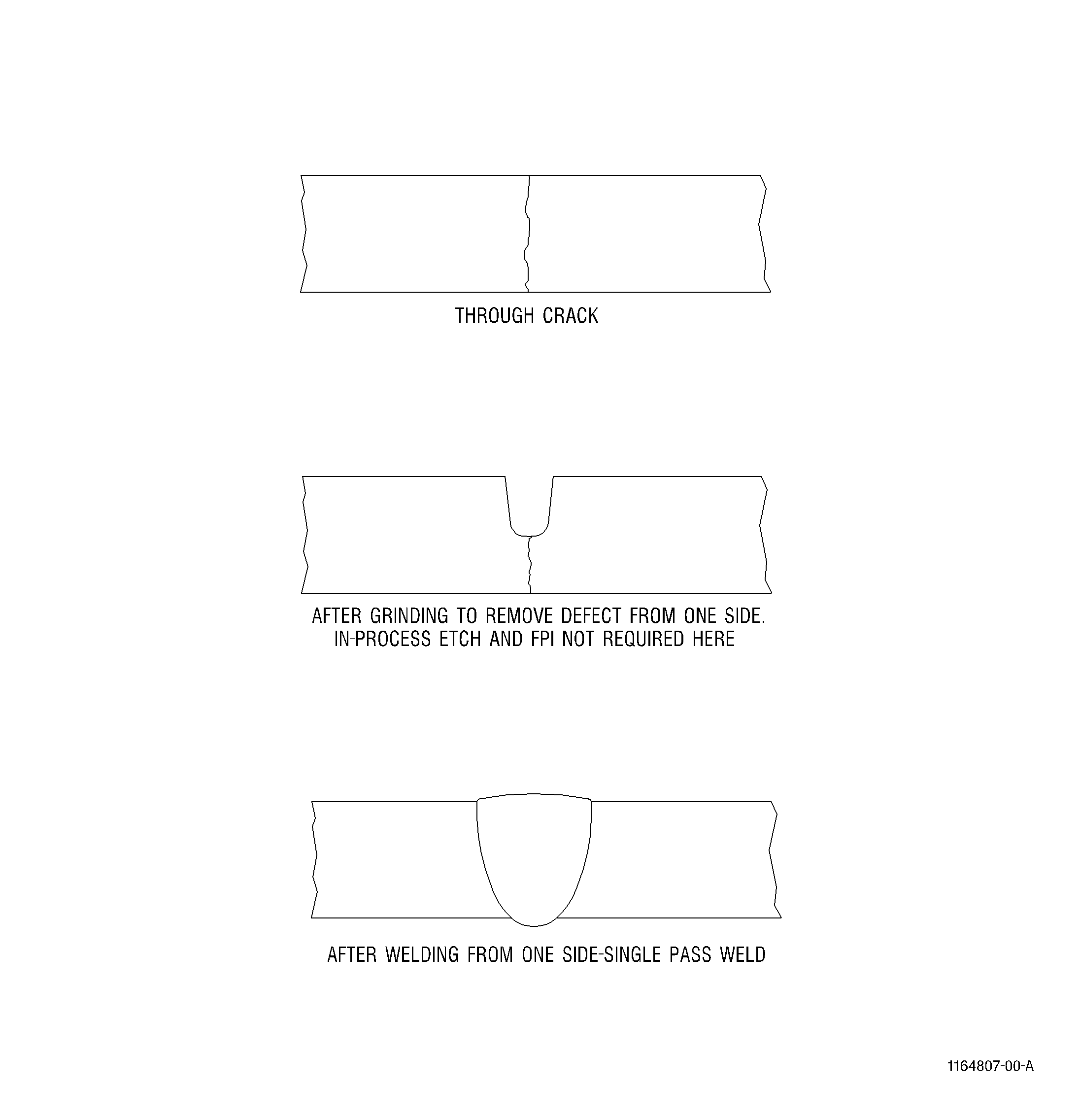
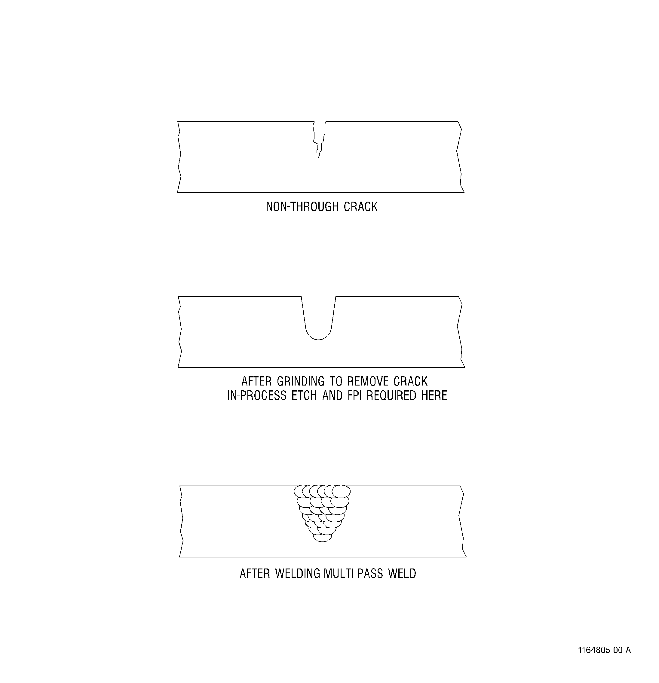
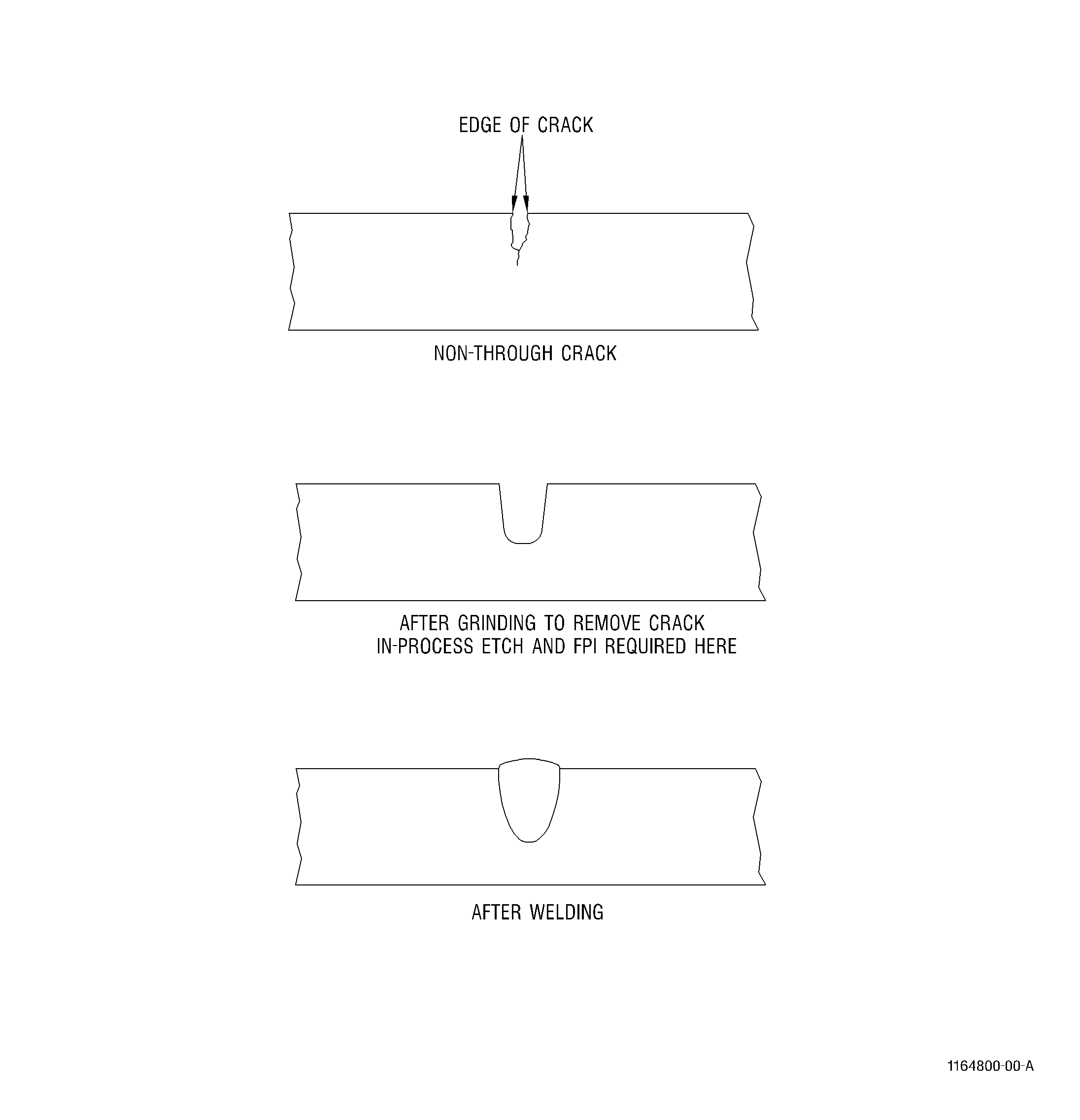
| F. | Remove stock from both edges of the crack to the minimum depth and width that exposes sound metal, and to a length approximately0.125 inch (3.18 mm) beyond each end of the crack. See Figure 5 and Figure 4. If a crack extends into a rivet hole, remove the rivet before welding. Grind or machine welds flush, and redrill or ream rivet hole before replacing rivet. If the crack extends through the entire thickness of the metal, remove stock to a depth proportional to the thickness, as follows: |
|
||||||||||||||||||||||||||||||||||||||||||||||||||||
| WARNING: |
|
| WARNING: |
|
| G. | Weld area should be cleaned with acetone C04-003 or methyl-ethyl-ketone C04-001 using a clean cotton cloth just prior to etching. |
| WARNING: |
|
| H. | Etch the prepared area per procedure and instructions in TASK 70-24-00-110-033, Etching Procedures for Fluorescent-Penetrant Inspection, and TASK 70-24-99-990-005, Consumable Materials. |
| Use appropriate etching solution per TASK 70-24-99-990-005, Consumable Materials. The shelf life of the etchants is given in TASK 70-24-00-110-033, Etching Procedures for Fluorescent-Penetrant Inspection. Swab etching may remove approximately 0.0001 inch (0.0025 mm) per minute as a general rule. |
| I. | Reinspect prepared areas in accordance with TASK 70-32-03-230-002, Spot-Fluorescent-Penetrant Inspection, or TASK 70-32-19-220-001, Enhanced Visual Inspection, to be sure that cracks are properly ground. |
| NOTE: |
|
| 4 . | Gas Backup. |
| Subtask 70-41-00-310-013 |
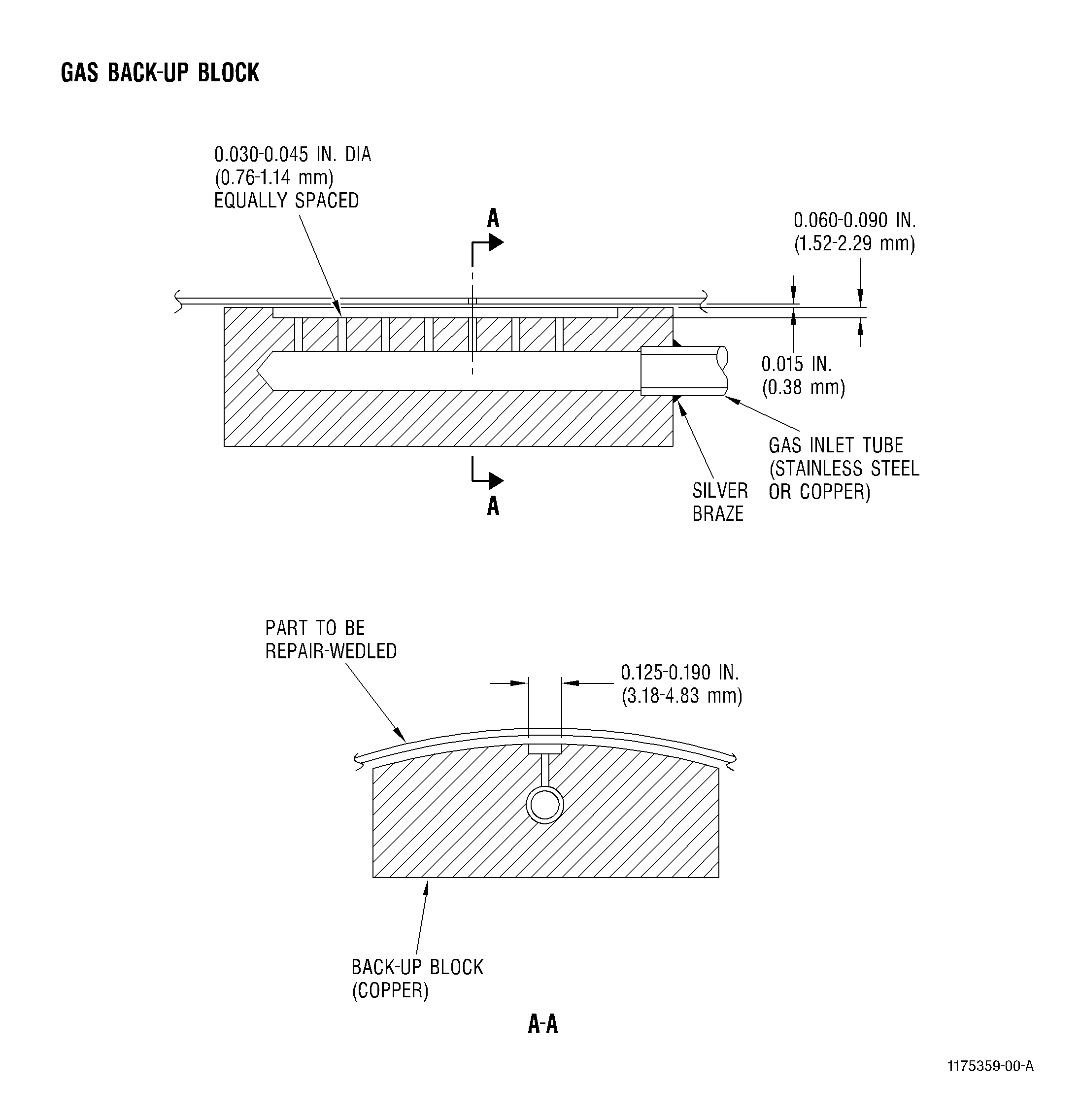
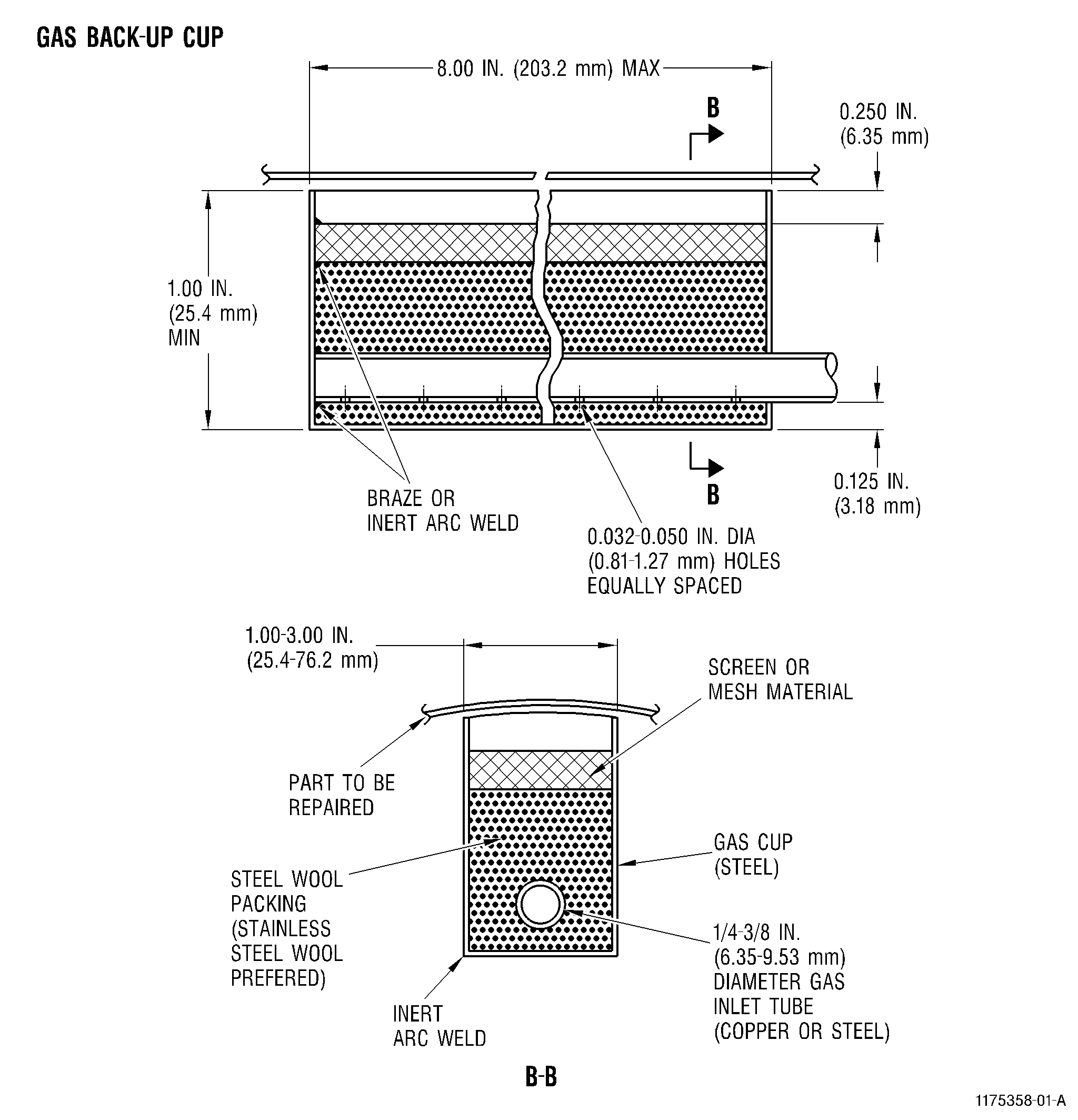
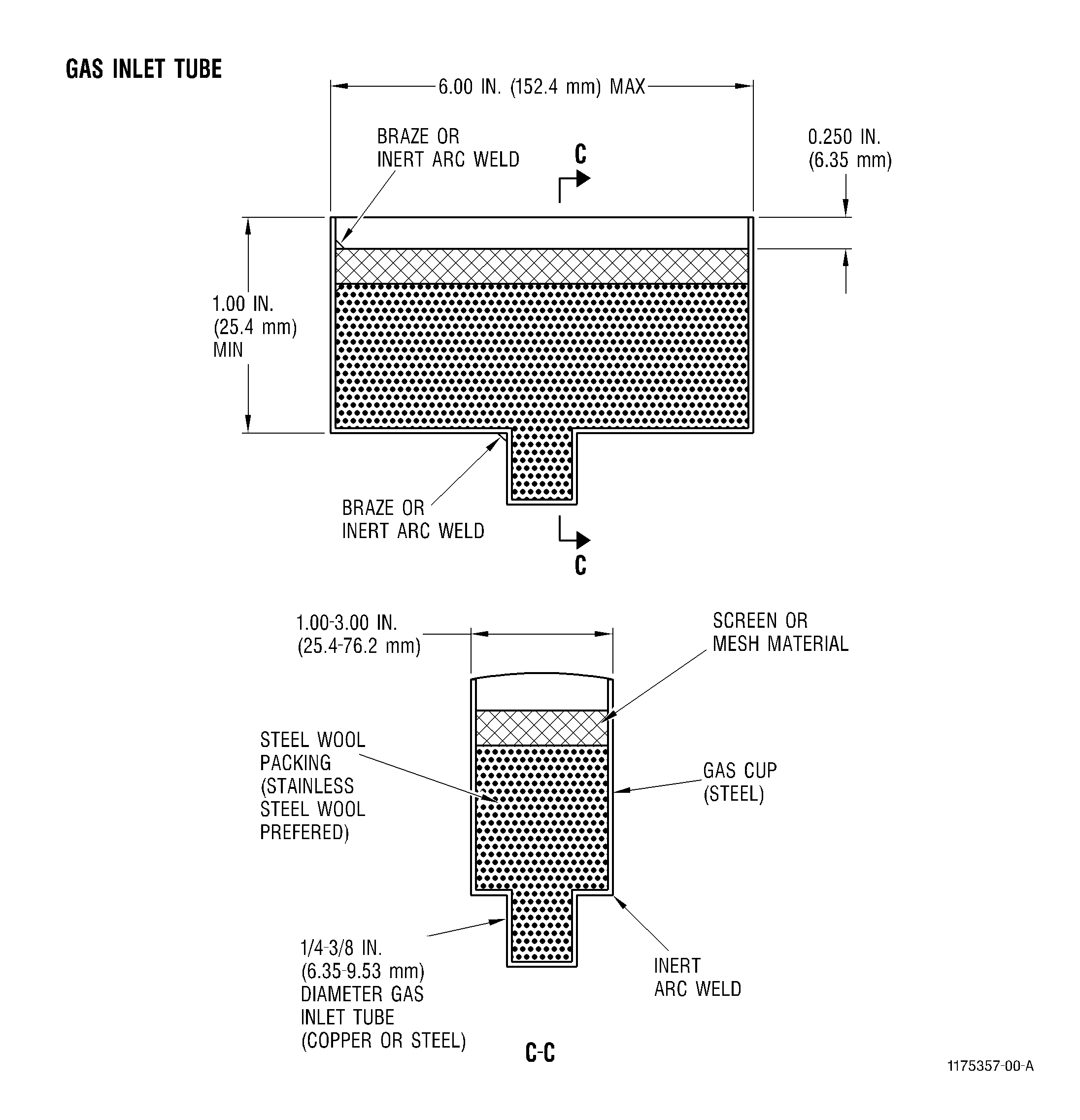
| A. | Gas backing is a method of isolating the weld area from air, vapors, and other contaminants by surrounding it with an inert gas such as argon or helium. Flow and diffusion must be carefully controlled to prevent turbulence at the air/gas boundary, which can cause contamination of the shielding gas and result in lack of penetration or oxide line defects in the weld. Application of the gas should be restricted to the area of the repair weld by the use of contoured copper backup blocks or backup cups, if the back surface of the weld is inaccessible. Refer to Figure 7. Perforated metal C10-095 or wire mesh cloth C10-094 for gas backup cups and inlet tube may be obtained from: |
| B. | If a fitted, grooved copper backup block is used, the gas grooves must provide non-turbulent gas flow to the back surface of the part, and the contoured surfaces of the block must fit the part sufficiently well to prevent air mixing with the gas. The gas exit apertures should be recessed about 0.060-0.090 inch(1.52-2.29 mm) from the surface, and the groove width should be about 0.125 inch (3.18 mm). |
| C. | If a gas cup is used, the diffuser should be recessed about 0.25 inch (6.4 mm) from the surface of the part. |
| D. | If the back surface of the weld is not accessible, the part should be sealed at all ports except for those used for gas inlet and exhaust. When this method is used, the internal space must be purged with shielding gas for a sufficient time to exclude all air from the area to be welded. |
| E. | Flow of shielding gas should be regulated to produce a silver colored bead. The flowrate (cubic feet per hour, cfh) depends upon the application and gas backup device. |
| 5 . | Tack Welding. |
| WARNING: |
|
| Subtask 70-41-00-310-014 |
| A. | Tacks are often used as an aid or alternate to fixturing prior to welding a joint to assist in joint alignment or for positioning of parts for brazing. During welding, tacks are used to counter the effect of "lift-off" that produces unacceptable offset conditions in the final weld. The use of tacks is minimal and often unnecessary with properly designed and built weld fixtures and with properly fitting component parts inputted to the weld station. |
| (1) | Gas backing shall be provided during the tack welding operation. Heavily oxidized tacks inhibit fusion during the subsequent welding operation and are not permitted. |
| (2) | No cracks are allowed in the weld bead of the tack and defects must not exceed those permitted for the primary weld. Deviations from this requirement may be allowed by specific Engine/Shop Manual repair. |
| (3) | Filler material may be used to avoid crater cracks. However, where filler material is used the reinforcement of the weld bead normally should not exceed 15 percent of the nominal stock sheet thickness. Where the reinforcement exceeds this value, the tack welds should be reworked by a benching operation using a rotary file to remove the excess material. Extra care must be taken to avoid getting metal filings in the exposed joint adjacent to the benched tack. |
| NOTE: |
|
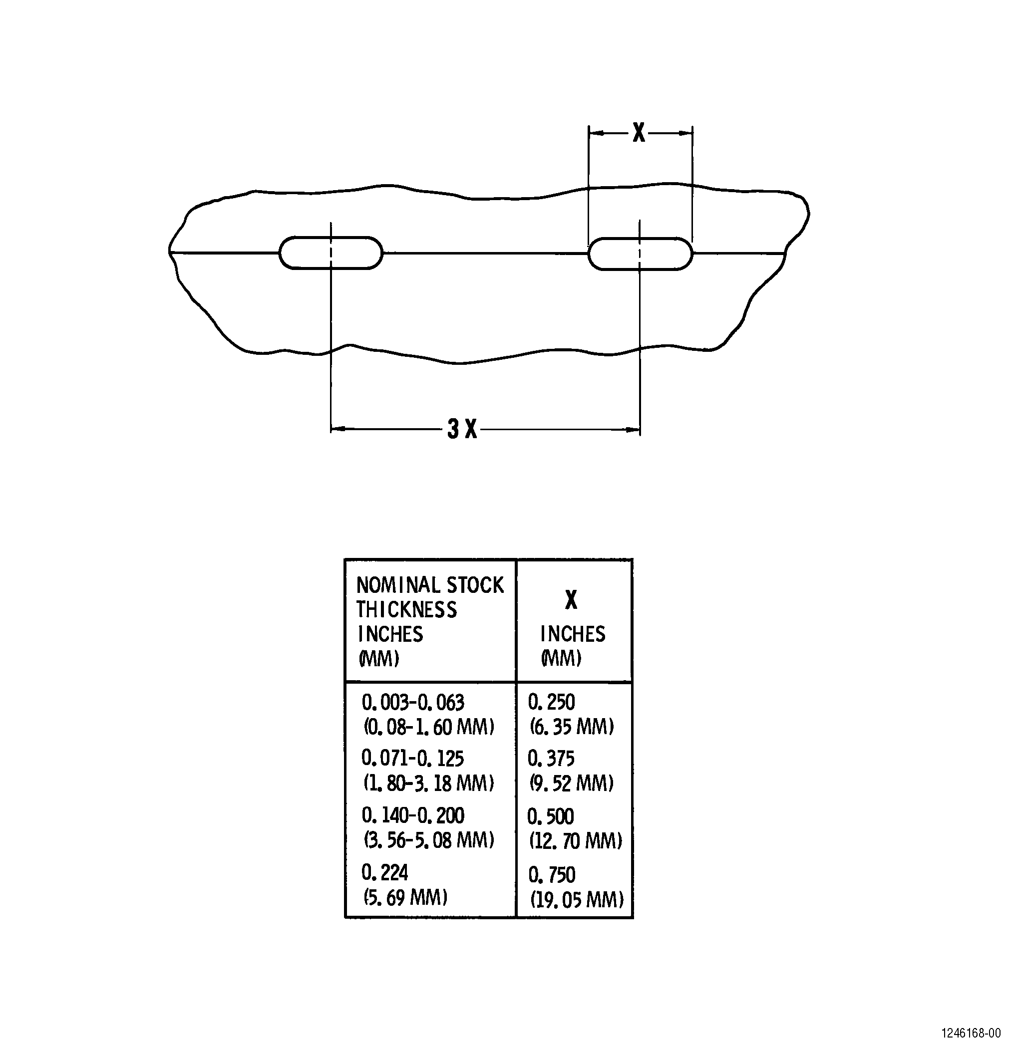
| (4) | Tack welds must be strong enough to perform their temporary fastening function. The size, length and spacing of the tacks depend largely upon the alloy, fitup conditions, and specific application. Figure 8 has lengths and spacings which, in the absence of specific information in the applicable Engine/Shop Manual repair, may serve as a guideline. |
| 6 . | Welding Processes and Equipment. |
| WARNING: |
|
| Subtask 70-41-00-310-015 |
| CAUTION: |
|
| CAUTION: |
|
| A. | Repair welding should be performed only by qualified, trained personnel. It is ordinarily expected that the parameters for each non-manual welded joint be specified on a process control document. When weld parameters are specified in a process document, then those parameters must be used to weld the joint. The following process and equipment are recommended for welding. |
| (1) | Process: Tungsten inert-gas shielded arc (also termed TIG, GTA, and GTAW) |
| NOTE: |
|
| NOTE: |
|
| (2) | Torch gas: Must be Argon and be 99.995 percent pure or better by volume when purchased. Recommended guidelines for Argon flow in cubic feet per hour (liters per minute), as a function of cup size, are shown as follows: |
|
| WARNING: |
|
| (3) | Electrode: 1/16-3/32 inch (1.6-2.4 mm) in diameter, 2 percent thoriated (thorium oxide), 1.5 percent lanthanated (lanthanum oxide) or 2 percent ceriated (cerium oxide) tungsten, ground to point are recommended for most applications. Zirtung is recommended for aluminum and magnesium. Electrode composition meeting AWS 5.12 standards are recommended. Selection of electrode type, diameter and preparation for welding should follow manufacturer's recommendations. |
| (4) | Control: A foot pedal control, variable-current device should be used to control heat input. |
| (5) | Welding Machine: |
| (a) | For Steel and Steel Alloys and High Temperature and Corrosion Resistant Alloys: |
| A DC type power source capable of being downsloped with a foot pedal control to low current is required to avoid craters, crater cracks and to adjust amperage during welding. |
| (b) | For Aluminum and Magnesium Alloys: |
| An AC type power source equipped with high frequency and capable of being downsloped with a foot pedal control to low current is usually required. D.C. reverse polarity welding with helium shield gas is also allowed. |
| B. | If multipass welding is required, the cleanliness of each bead must be visually verified prior to making additional passes. Machanical cleaning by grinding, rotary filing or wire brushing, must be done if needed. |
| WARNING: |
|
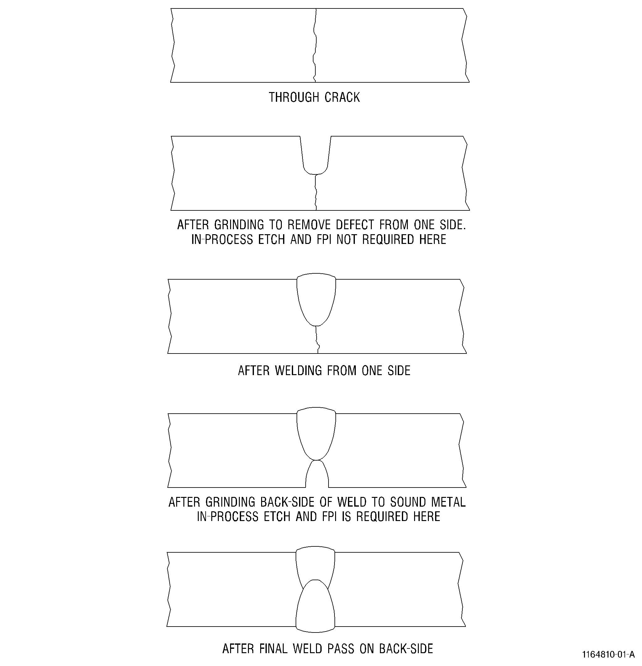
| C. | Where welding is performed from both sides, the root side shall be ground or rotary filed to sound metal by removing stock from both edges of the crack, and to a length approximately 0.125 inch (3.18 mm) beyond each end of the crack, etched per TASK 70-24-01-110-034, Swab Etching Procedure, and inspected in accordance with TASK 70-32-03-230-002, Spot-Fluorescent-Penetrant Inspection. See Figure 2. Clean with stainless steel wire brush, and wipe area with a clean cloth moistened with acetone C04-003 before welding. |
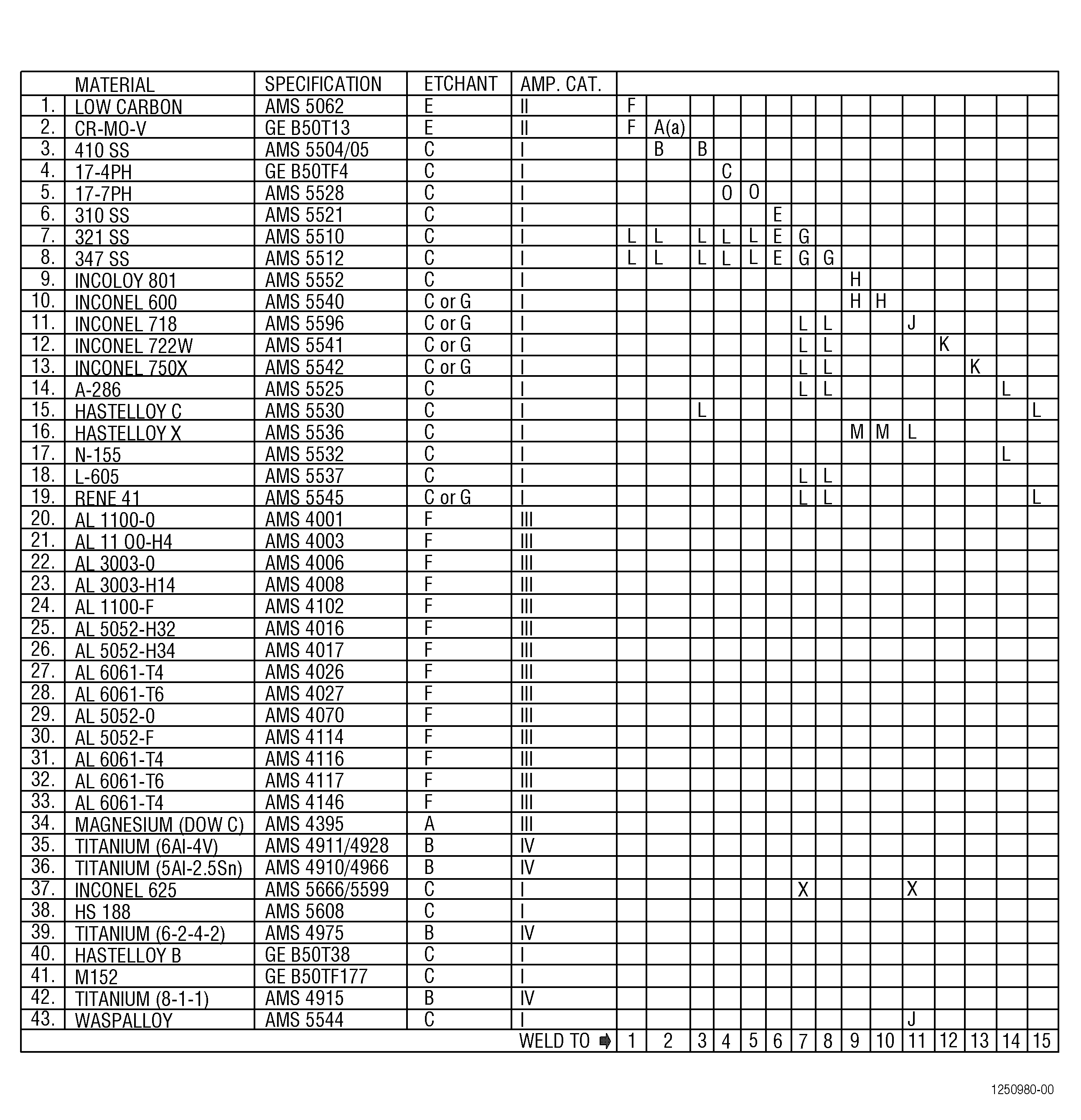
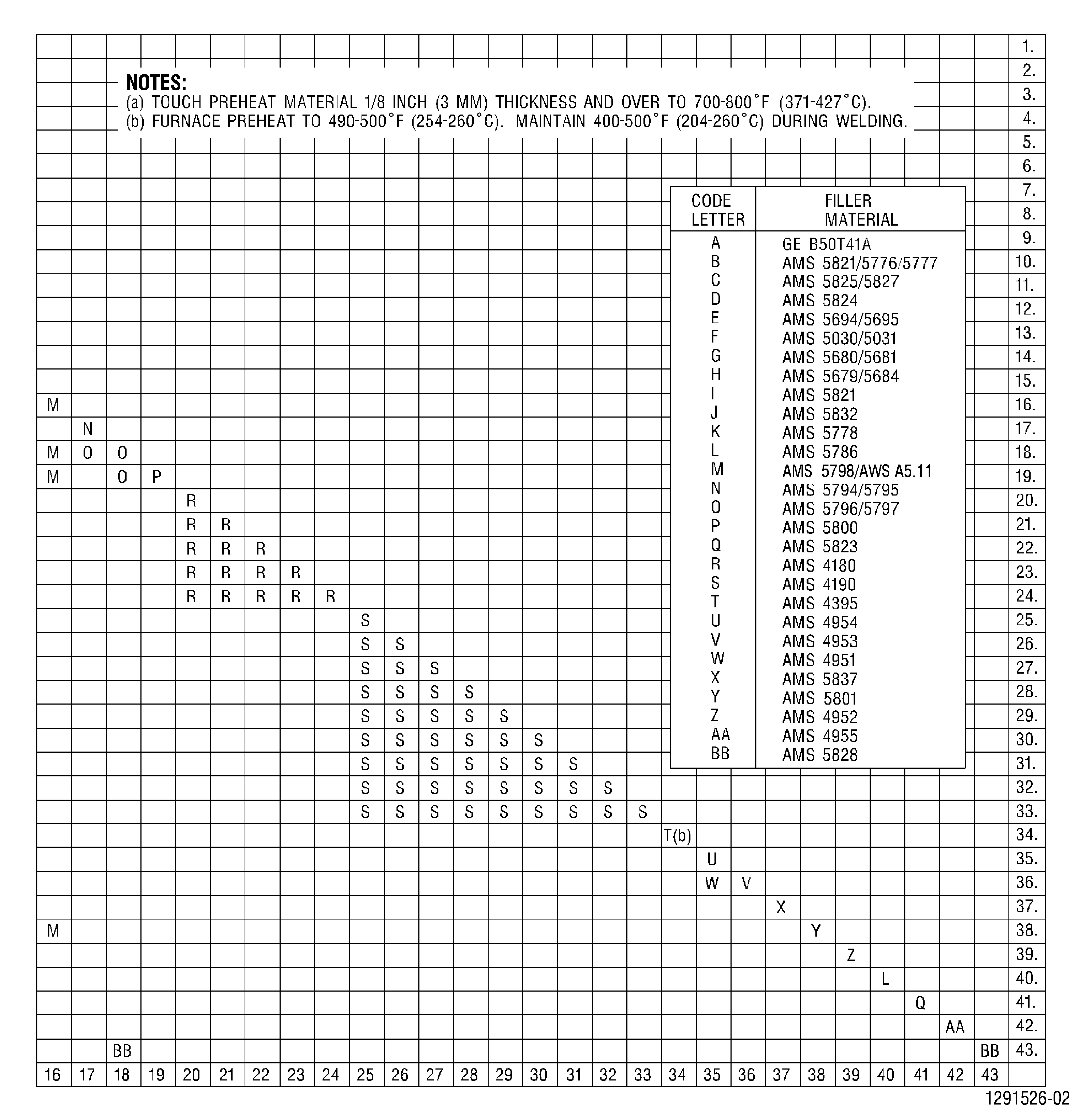
| D. | The use of filler wire is recommended for most repairs. Unless otherwise specified in the process document, use Figure 9 to determine the proper wire to be used. |
| (1) | Filler wire should be stored in such a manner as to protect it from contamination, dust, dirt, oil, etc., both in the filler storage area and the weld booth. |
| (2) | It is recommended that used ends on the filler material be clipped before use to prevent the oxidized filler material from contaminating the weld pool. |
| (3) | Titanium filler wire must be stored in an Argon or non-oxidizing environment. Methods for storage may include sealed bags or a box purged with a dry, non-oxidizing gas. |
| NOTE: |
|
| (4) | Cut length filler wire must be identified with a flag tag or other suitable method indicating the alloy specification. Remarking of weld wire by the repair source is not permitted. |
| (5) | Spooled filler wire must be identified indicating the alloy specification. The alloy specification marking must be visible when the spool is in use on the machine. |
| E. | After repair welding, clean the weld per the applicable Engine/Shop Manual section to remove oxides, and inspect in accordance with TASK 70-32-03-230-002, Spot-Fluorescent-Penetrant Inspection, or TASK 70-32-19-220-001, Enhanced Visual Inspection, to be sure that the defects were properly welded. The acceptance inspection of the weld repaired area must be performed in accordance with TASK 70-32-03-230-002, Spot-Fluorescent-Penetrant Inspection, or other methods specified in the Engine/Shop Manual so that the final inspection requirements of the Engine/Shop Manual are complied with. |
| F. | The parameters specified on the process control document must be used for all welds to which they apply. Amperage may vary with thickness and type of material to be repair welded. Table 1 lists the suggested amperage for different thicknesses of materials by weld type categories and may be used as a reference when developing a weld schedule. |
| NOTE: |
|
|
|||||||||||||||||||||||||||||||||||||||||||||||||||||||||||||||||||||||||||||||||||||||||||||||||||||||||||||||||||||||||||||||||||||||||||||||||||||||||||||||||||||||||||||||||||||||||||||||||||||||||||
| 7 . | Approval of Welding Equipment and Welding Systems. |
| Subtask 70-41-00-310-016 |
| A. | The installation for fusion welding must be suitable for the nature of work to be performed, and must comply with specifications existing in the aircraft industry and the official regulations in force in the country where the repair shops are situated. The equipment must be checked periodically for correct operation and safety, at least once per year. |
| B. | Calibration of welding equipment instruments and gages for non-manual applications is ordinarily expected. Recommended guidelines for equipment calibration are as follows. Calibration of weld current (±5%), arc/AVC voltage (larger of ±5% or 1V), travel speed (±5%) and wire feed speed (±5%). Calibration of travel speed and wire feed speed is not needed if parameter verification is performed by the weld operator for each batch of parts welded. Parameter verification of wire feed, for example, can be done by feeding wire for 15 seconds and multiplying the actual inches fed by four to determine inches/minute. |
| C. | For applications where pre-heat is used, temperature verification prior to welding is required. Examples of temperature verification methods include optical or contact pyrometry and thermocouples. |
| 8 . | Qualification of Personnel. |
| Subtask 70-41-00-310-017 |
| A. | All the welding personnel carrying out repairs by manual, machine, or automated welding on aircraft engine components must be highly qualified and satisfy the following conditions: |
| (1) | Possess a valid certificate of proficiency for the process and the metal employed. |
| (2) | Have correctly carried out one or more test welds to demonstrate ability before producing any new component or each set of components. |
| NOTE: |
|
| B. | The testing and certification requirements shall be in accordance with the appropriate national air regulation(s) and/or specifications existing in the aircraft industry. A typical standard used for the Qualification of Welding Personnel is AMS-STD-1595 or AWS D17.1. |
| C. | Enter in a log document the level of proficiency results attained and their dates. |
| D. | The welder must ensure that his skill level always remains valid by obtaining acceptable results and when necessary, by submitting himself to a new examination for proficiency. |
| NOTE: |
|
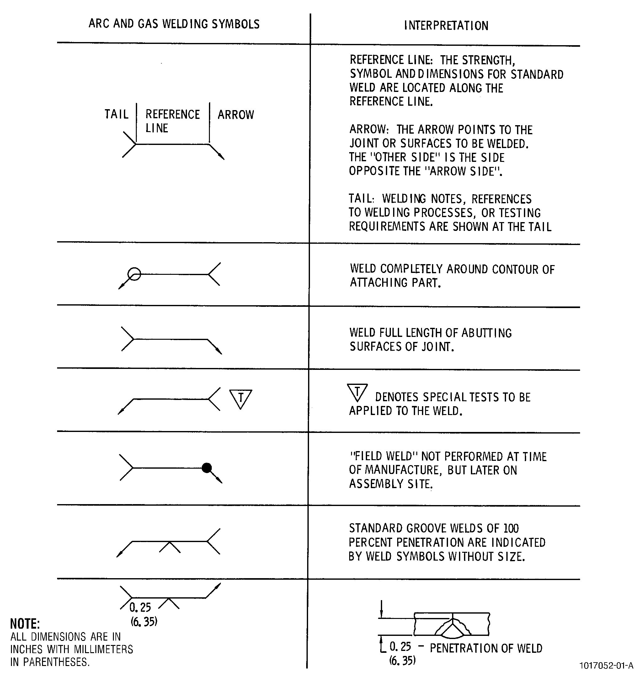
| 9 . | Welding and Brazing Symbols. |
| Subtask 70-41-00-310-018 |
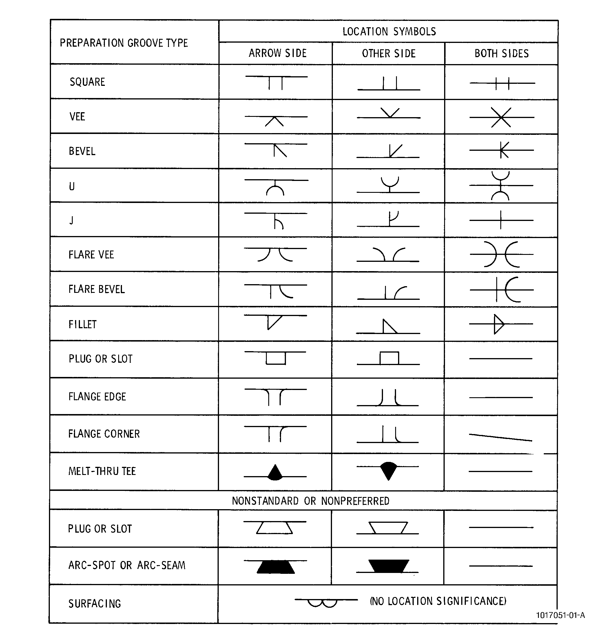
| A. | Joint Preparation Symbols. |
| The joint preparation symbols( Figure 12) are used in conjunction with the appropriate welding symbols( Figure 11) to provide the necessary structural information on standard welds. When symbols are not sufficiently explanatory, dimensions and notes pertaining to the weld may be used. Resistance welding and supplementary symbols are shown in Figure 10. |
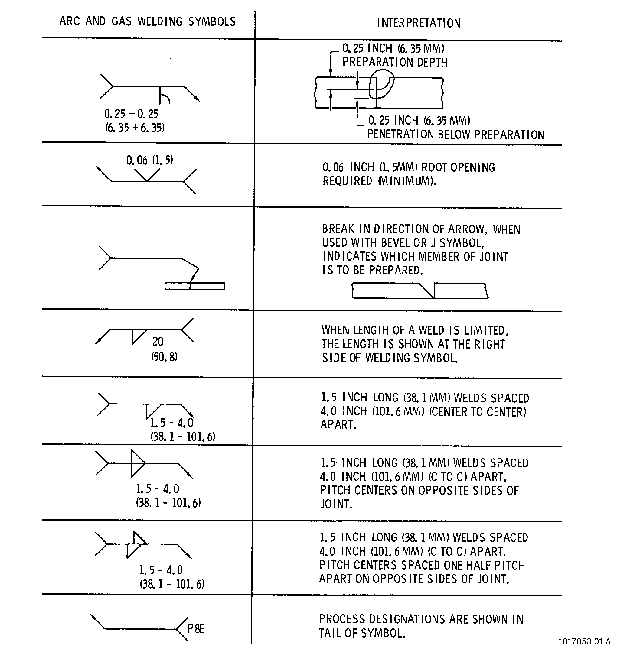
| B. | Welding Symbols. |
| The composite welding symbol, made up of the surface designating arrow, type of joint preparation, and various finish, spacing or positioning symbols, often includes a process designation in the tail of the symbol. The process designations cover the different types of operations used in welding, brazing and soldering. |
| C. | Processing Designations. |
| Process designations for various types of joints appear as symbols in the tail of the welding symbol. These designations are defined as follows: |
| (1) | Arc and gas welding. |
| (a) | P8B (Metal arc, coated electrode). In this process, the heat is obtained from an arc formed between the work and a coated metal electrode which supplies molten filler metal to the joint. The coating of the electrode consists of a flux which protects the weld metal. |
| (b) | P8E (Gas welding). In this process, heat is produced by a gas flame. Flux can be used for protection of the molten puddle. |
| (c) | P8F (Submerged arc). In this process, heat is produced by an electric arc between a consumable bare metal electrode and the work. Shielding is provided by a blanket of granular flux over the weld puddle or deposit. |
| (d) | P8G (Gas-shielded tungsten arc). In this process, heat is obtained from an arc between a tungsten electrode and the work in a shielding atmosphere of inert gas. |
| (e) | P8J (Gas shielded metal arc). In this process, heat is obtained from an electric arc between a consumable electrode and the work in a shielding atmosphere of inert gas. |
| (f) | P8K (Electron beam welding). Electron beam welding is a fusion joining process in which the workpiece is bombarded with a dense focused stream of high velocity electrons where the kinetic energy of the electron particles is transformed into heat upon workpiece impact. Electron beam power is developed in a gun under high vacuum; however, actual welding can be performed either in vacuum (usually) or in the atmosphere. |
| (g) | P8P (Plasma arc). In this process, heat is obtained from an electric arc in highly ionized gas called a plasma. The arc may be either transferred (between electrode and work) or nontransferred(between electrodes within the torch). Inert gas is used as the shielding medium. |
| (h) | P8R (Resistance welding). A group of welding processes in which welds are made by heat resulting from the resistance of the work to the flow of electric current through it and by the simultaneous application of force. |
| (2) | Brazing. |
| NOTE: |
|
| (a) | P9B (Resistance brazing). A process in which the brazing heat is obtained from resistance to the flow of electric current in a circuit of which the work is a part. |
| (b) | P9D (Induction brazing). A process in which the brazing heat is obtained from resistance of the work to the flow of induced electric current from a surrounding coil. |
| (c) | P9E (Arc brazing). A process in which the brazing heat is obtained from an electric arc. |
| (d) | P9F (Furnace brazing). A process in which the brazing heat is obtained by placing the prepared work in a furnace. |
| (e) | P9G (Gas-torch brazing). A process in which the brazing heat is obtained from gas flame. |
| (f) | P9H (Metal-bath brazing). A process in which the brazing heat is obtained from a bath of molten filler metal. |
| (g) | P9J (Flux-bath brazing). A process in which the brazing heat is obtained from a bath of molten flux. |
| (h) | P9K (Heat lamp brazing). In heat lamp brazing, joining or coalescence of metallic materials is produced above 800°F(427°C) by use of radiant heat obtained from high temperature bulbs or lamps. Lamp heat output energy is usually focused on the workpiece by reflectors. Atmospheres surrounding the brazing alloy and base metal is usually obtained by use of a flux, inert gas or a combination of both. |
| (3) | Soldering. |
| NOTE: |
|
| (a) | P18B (Resistance soldering). A process in which heat is generated by resistance to the flow of electric current through the joint between 2 nonconsumable electrodes. Flux may be applied to the joint before heating. |
| (b) | P18D (Induction soldering). A process in which heat is generated in the joint by resistance to an electric current by means of a surrounding coil. Both solder and flux are applied to the joint before heating. |
| (c) | P18E (Arc soldering). A process in which soldering heat is generated by an arc between the joint and a nonconsumable electrode. Solder may be added while the arc is maintained. |
| (d) | P18F (Furnace soldering). A process in which soldering heat is obtained by placing the assembled joint (with flux applied and solder in place) in a furnace. |
| (e) | P18G (Gas torch soldering). A process in which soldering heat is applied to the joint with a gas flame. Normally, flux is applied before heating, and solder applied in wire form when the joint is hot enough to melt it. Flux-cored solder may also be used. |
| (f) | P18H (Metal-bath soldering). A process in which the joint is prepared, flux applied, then dipped into a bath of molten solder, or molten solder flowed over the joint. |
| (g) | P18J (Flux-bath soldering). A process in which the joint is prepared, solder placed in position, and the joint dipped into a bath of molten flux. |
| (h) | P18K (Soldering-iron, soldering-gun, or soldering-pencil soldering). A process in which the heated soldering tool transfers heat to the joint to raise it to soldering temperature. Flux may be applied before heating or added with the solder in cored wire form. |
| 10 . | Weld Joint Geometry and Terminology. |
| Subtask 70-41-00-310-019 |
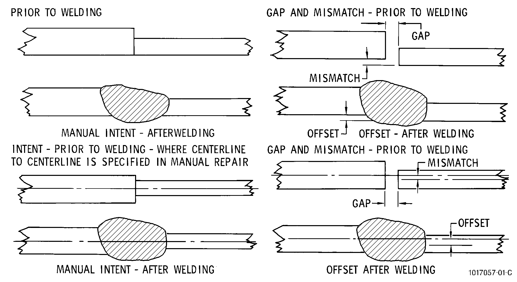
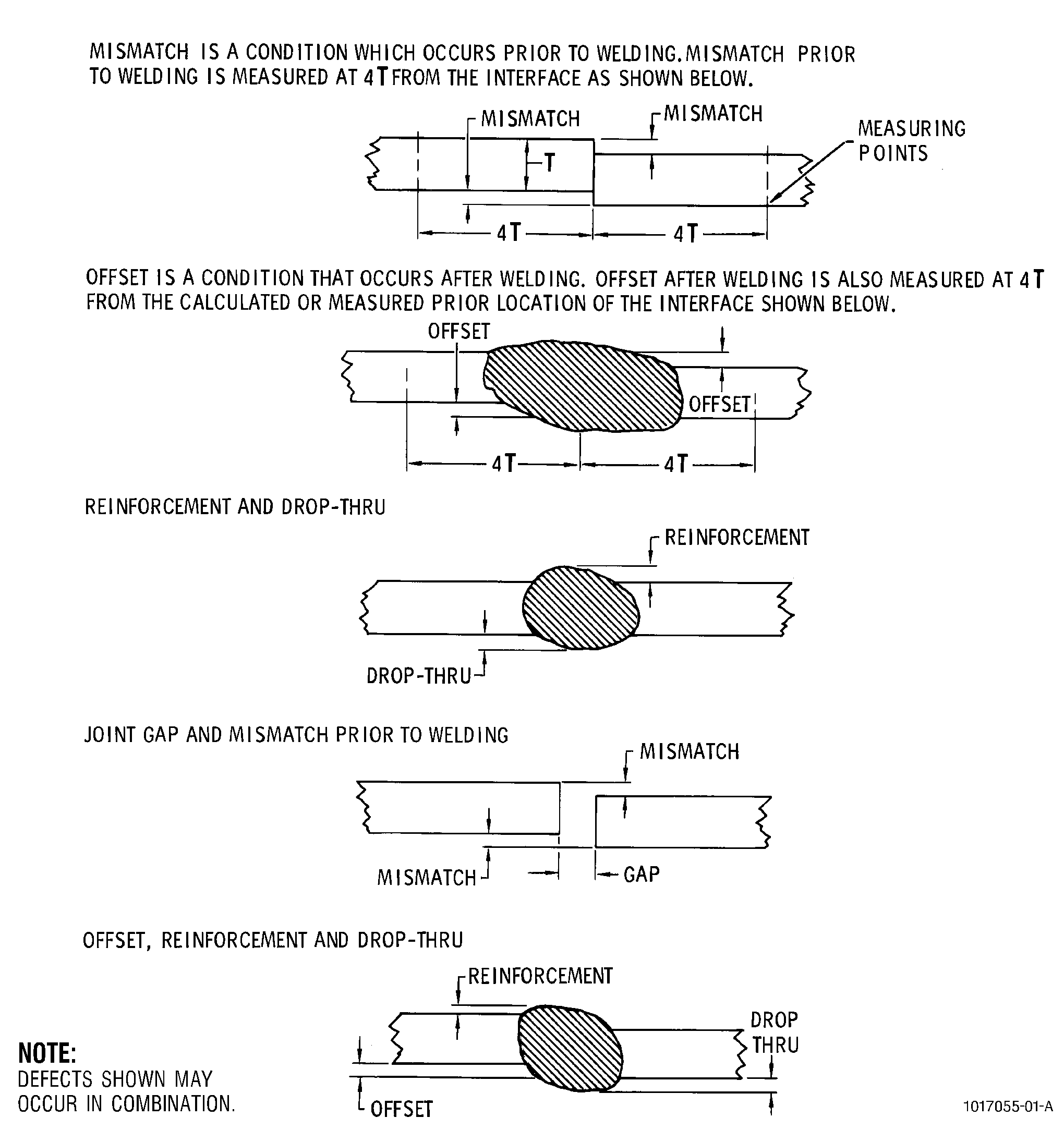
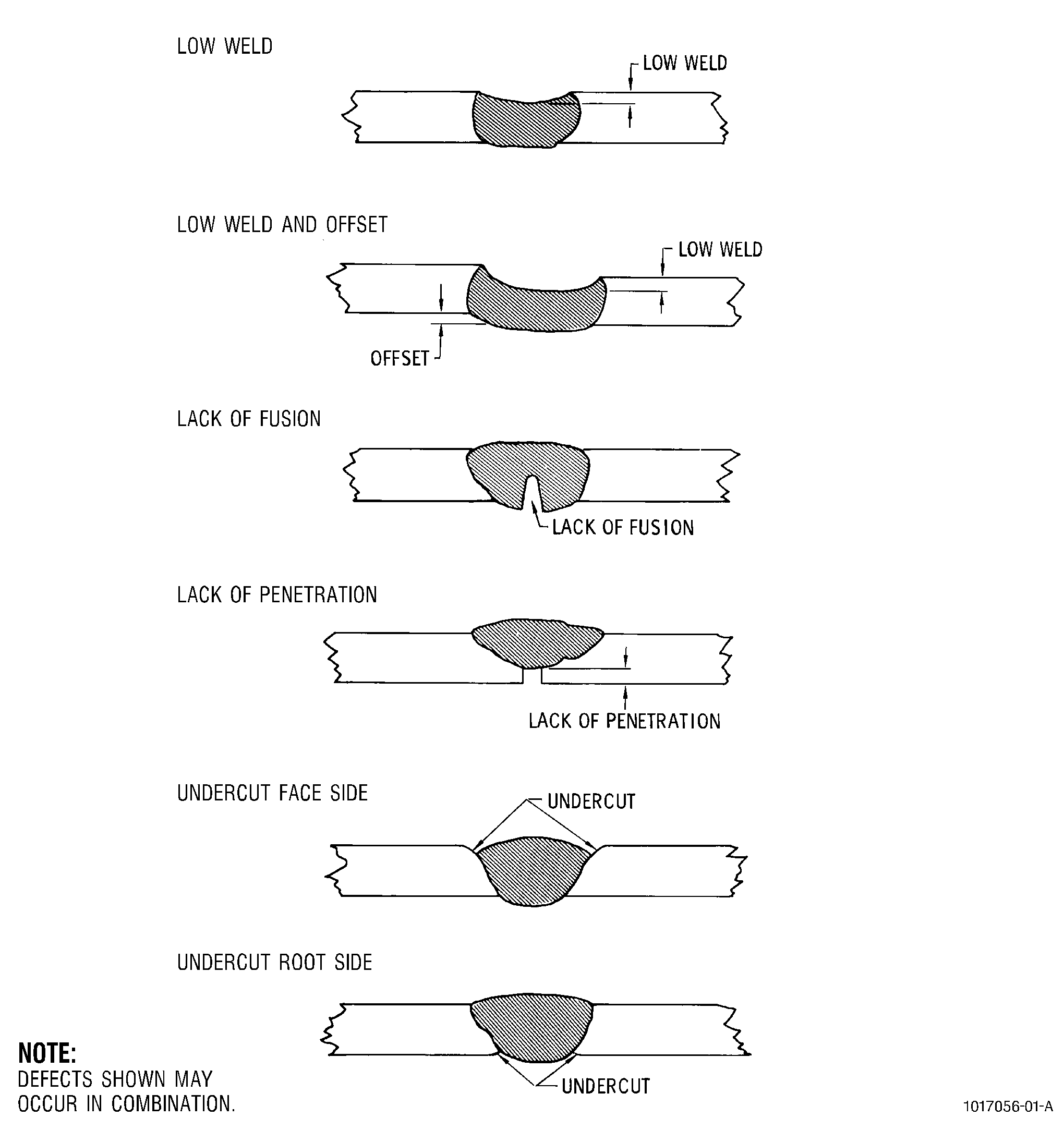
| A. | The following describes weld geometries that are typical of all welded joints and may be used as a guide when the Engine/Shop Manual repair calls for specific joint geometry requirements in terms of joint fitup and weld bead quality. The following depicts variations which may occur when performing butt welds and the terminology that applies to them. |
| Weld joint preparation is per the specific part Engine/Shop Manual repair instructions and Subtask 70-41-00-310-012, Preparation for Welding. For purposes of clarity the illustrations show square butt joints but may be applied to any method of welding or any method of joint preparation. Joint fitup prior to welding is determined by the root gap opening and the mismatch conditions that exist between the mating surfaces after the parts have been tack welded together. Joint fitup is an extremely important factor in the fabrication of sheet metal components. In most cases, joint gap and mismatch prior to welding should be held to a minimum. In all cases where specified in a Engine/Shop Manual repair, those values must be observed. |
| (1) | Equal Stock Thickness. |
| Figure 15 illustrates joint geometry and terminology as made between materials of equal nominal thickness at the joint interface and back to 4 times the thickness from the interface. Ideally, joint geometry without any of the deviations shown is desired. The acceptance criteria for each characteristic must be per the applicable Engine Shop Manual repair or Service Bulletin. |
| (2) | Unequal Stock Thickness. |
| Square butt joints may be made between materials of unequal thickness as directed by the Engine/Shop Manual. It is important that the repair intent relative to sheet centerline alignment be clear. Sheet thickness ratio (thick-to-thin) should not exceed2.0, based on nominal thickness, unless otherwise directed by specific Engine/Shop Manual repair. When sheet thickness ratio exceeds2.0, the thicker sheet should be prepared such that the ratio at the interface does not exceed 1.2, unless otherwise directed by a specific repair. Figure 14 illustrates joint possibilities between materials of unequal stock thickness. All of the definitions noted in step (1), above, and Figure 15 also apply here, as applied to the thinnest member. The acceptance criteria for each characteristic must be per the applicable Engine Shop Manual repair or Service Bulletin. |
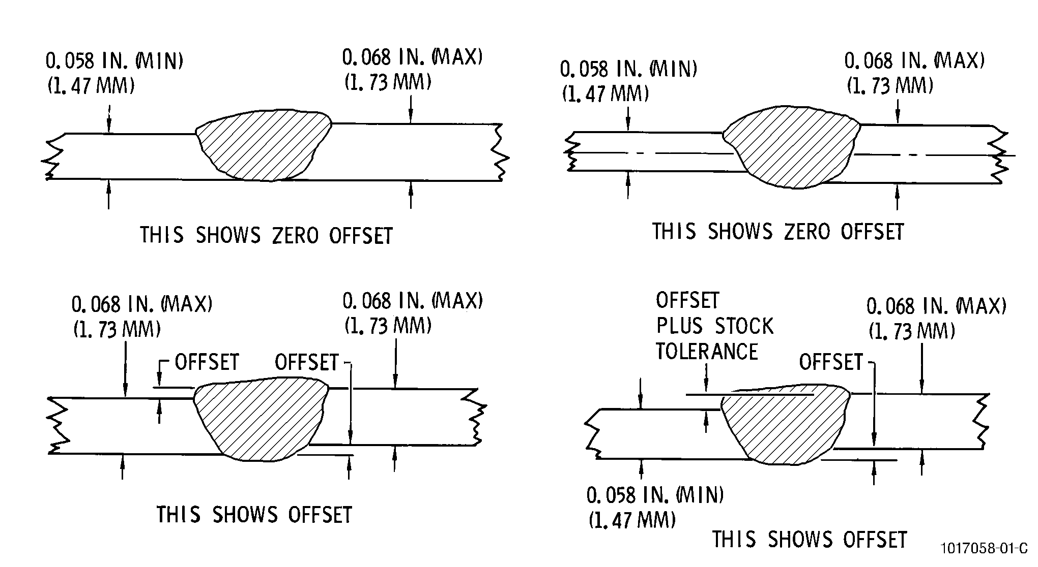
| (3) | Effects of Stock Tolerance. |
| The effects of stock tolerance on offset definition is illustrated in Figure 13. Offset is measured in addition to known variation in actual stock thickness. The examples shown in Figure 13 show the effects of stock tolerance on offset for 0.063 inch (1.60 mm) nominal [0.058-0.068 inch(1.47-1.73 mm)] stock. All of the definitions noted in steps A and B, above also apply here. |
| 11 . | Brazing. |
| Subtask 70-41-00-310-020 |
| WARNING: |
|
| A. | General. |
| (1) | Brazing is a process where components are joined using a filler metal (alloy) which melts above 800°F (427°C) and below the melting point of the materials being joined. The filler metal is distributed between component joint surfaces by capillary attraction. To obtain good joint strengths from the brazing process, cleanliness of components, joint clearances, time at brazing temperature, and application of filler metal must be controlled. |
| (2) | Filler metals from brazing are classified by solidus/ liquidus temperature. The solidus temperature is the highest temperature at which a metal is completely solid. The liquidus temperature is the lowest temperature at which a metal is completely liquid. The brazing temperature can vary from 15 to 150°F (8 to 83°C) higher than the liquidus temperature and is dependent on the particular properties and application of each filler metal. The brazing temperature must be lower than the solidus of components being joined. |
| (3) | Capillary attraction is that property of liquids which promotes self-sustained flow between mating surfaces and which proceeds until an equilibrium between weight of liquid and surface tension is reached or until the capillary gap is filled. Surface tension is an inherent characteristic of all liquids, including filler metals. |
| The flow it produces is strongly influenced by cleanliness and surface finish of the components being joined, joint clearance, purity of atmosphere, cleanliness of filler metal, correct brazing temperatures as measured by actual part temperatures, and by proper placement of the filler metal at or within the joint. |
| (4) | Total braze time must be determined for each application. The time required at brazing temperature to complete the flow of the filler metal is normally 5 to 15 minutes after the components to be joined have reached the required temperature. |
| B. | Types of Brazing. |
| Brazing processes are designated by the method of heating. The methods normally used are furnace brazing, torch brazing, and induction brazing. |
| (1) | Furnace brazing (TASK 70-41-03-310-004, High Temperature Furnace Braze). |
| (a) | Furnace brazing is used extensively where the parts to be brazed can be assembled with the filler metal preplaced near or in the joint. The preplaced filler metal may be in the form of wire, foil, filings, slugs, powder, paste, tape, etc. Fluxing is usually employed except when an atmosphere is specifically introduced in the furnace to perform the same function. |
| (b) | Some furnace brazing is accomplished in a reducing gas atmosphere such as hydrogen, and either exothermic or endothermic combusted gas. Pure, dry inert gases such as argon or helium are employed to obtain neutral atmospheric conditions. The brazing atmosphere is either maintained in a retort or the furnace itself. |
| (c) | The types of furnaces used are heated by either electrical resistance elements, gas, or oil and should have automatic time and temperature controls. Cooling is sometimes accomplished by cooling chambers which are either placed over the hot retort or are an integral part of the furnace design. Forced atmosphere injection is another method of cooling. Parts may be placed in the furnace singly or in batches. |
| (d) | Some furnace brazing is performed in a vacuum. This prevents oxidation and often eliminates the need for flux. Vacuum brazing has wide application in the aerospace field where reactive metals are joined or where entrapped fluxes would be intolerable. If the vacuum is maintained by continuous pumping it will remove volatile constituents liberated during brazing. |
| There are several base metals and filler metals, however, which can be harmed by brazing in a vacuum as their low boiling point or high vapor pressure constituents cause a part of the metal to be lost. |
| (e) | Vacuum is a relatively economical method of providing an accurately controlled brazing atmosphere. Vacuum maintains the surface cleanliness needed for good wetting and flow of filler metal without the use of fluxes. |
| Base metals containing chromium and silicon, which normally require very pure, low dewpoint atmosphere gas for brazing, are easily vacuum brazed. Super alloys containing highly reactive aluminum and titanium may be brazed in vacuum although prior surface plating is recommended to improve wet-out or braze flow characteristics. |
| (2) | Torch brazing (TASK 70-41-02-310-003, Brazing of Joints in Formed Tubing). |
| (a) | As the name implies, torch brazing is accomplished by heating with a gas torch or torches. Depending upon the temperature and the amount of heat required, the fuel gas (acetylene, propane, natural gas, etc.) may be burned with compressed air or oxygen. The quality of the gases used for torch brazing must be controlled so that the resulting braze joint meets all the requirements of the Engine Shop Manual repair or Service Bulletin. The requirements of TASK 70-00-06-800-007, Quality of Gases do not apply to torch brazing. As a guideline, a gas quality of 32 ppm of moisture or -60°F (-51°C) dew point is ordinarily considered acceptable for torch brazing. |
| NOTE: |
|
| (b) | Brazing filler metal may be preplaced in the forms of rings, washers, strips, slugs, powder, etc., or it may be fed from hand-held filler metal, usually in the form of wire or rod. In any case, proper cleaning and fluxing are essential. |
| (c) | For manual torch brazing, the torch may be equipped with a single tip. Manual torch brazing is particularly useful on assemblies involving sections of unequal mass. |
| (3) | Induction brazing. |
| (a) | The heat necessary for brazing with this process is obtained from an electric current induced in the parts to be brazed, hence the name induction brazing. |
| When induction brazing, the parts are placed in or near an alternating current-carrying coil and do not form a part of the electrical circuit. The brazing filler metal is usually preplaced. Careful design of the joint and the coil set up are necessary to ensure that the surfaces of all members of the joint reach the brazing temperature at the same time. Flux is usually employed except when a atmosphere is specifically introduced to perform the same function. |
| (b) | The three common sources of high-frequency electric current used for induction brazing are the motor generator, spark-gap converter, and vacuum tube oscillator. |
| (c) | The depth of heating by induction depends primarily on the frequency of the alternating current. As the frequency is increased, both the depth of the current penetration and depth of the heated zone in the workpiece decreases. For example, the theoretical depth of current penetration is about 0.035 inch (0.89 mm) at a frequency of 3 kHz but decreased to about 0.003 inch (0.08 mm) at 500 kHz. Frequency ranges from 60 Hz to 460 Hz are used in induction brazing. The higher frequencies should be selected when shallow heat penetration is desired. For the majority of brazing applications, the frequencies used are seldom below 10 kHz, the peak frequency obtainable from motor-generator power supply units. |
| (4) | Arc brazing. |
| (a) | Arc brazing is defined as a brazing process using a Gas Tungsten Arc (GTA) welding torch as the heat and inert gas shielding source. This process has also been called TIG brazing. This process provides a more localized heating than that which occurs with Torch Brazing (P9G). |
| “The filler metal is added to the braze joint using wire. The base metals are not melted, only the filler metal melts. Bonding takes place between the deposited filler metal and the hot unmelted base metals in the same manner as conventional brazing. Capillary action is not a factor in distribution of the brazing filler metal. The filler metal is melted and deposited in grooves and fillets exactly at the points where it is to be used.” (Source: AWS Welding Handbook, Volume 2, eighth edition, pages 380 and 414). |
| Braze fluxes are not used with this process. Prior to braze, the joint faces and adjacent surfaces of the base metal must be cleaned to remove all oxides, dirt, grease, oil, and other foreign material. |
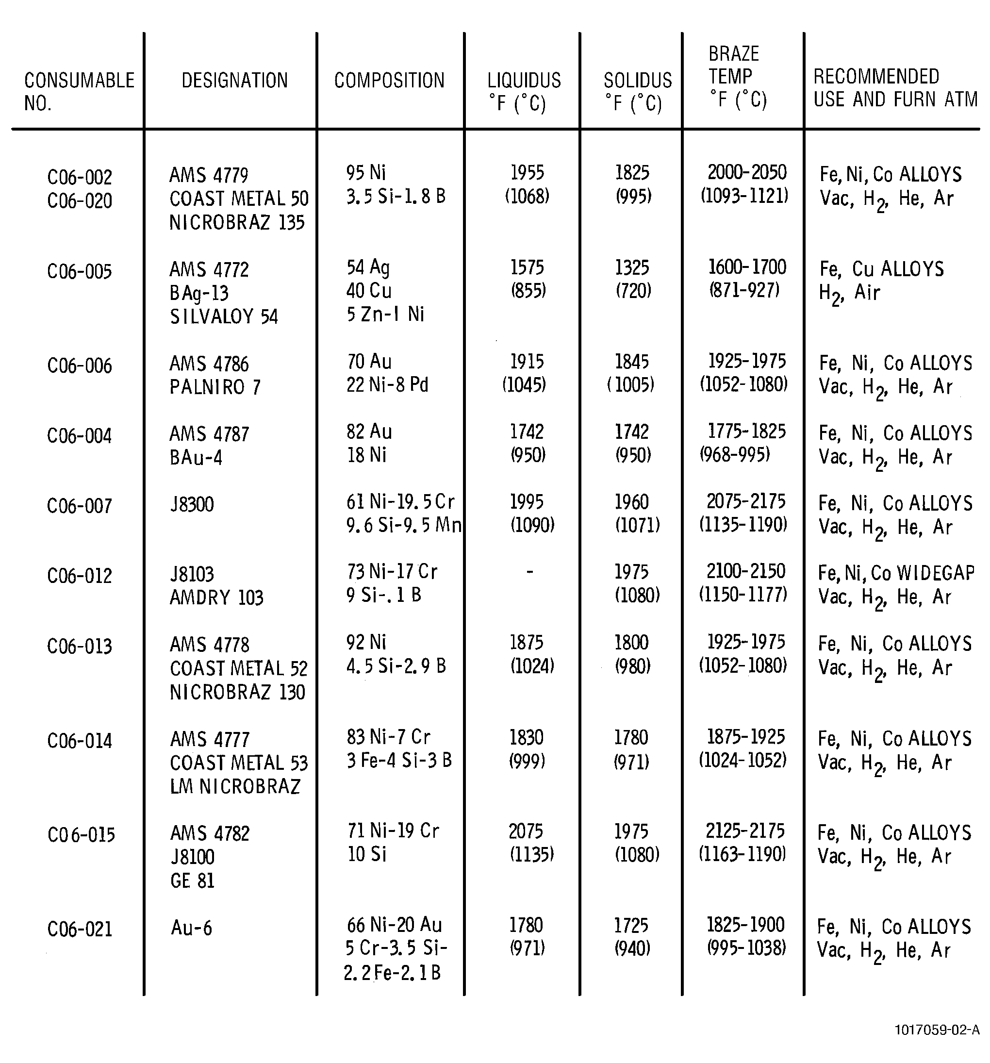
| C. | Filler Metals. |
| Filler metals and brazing temperature will be specified in each repair. Figure 16 lists the most common brazing alloys used in the repair of parts, their composition, brazing temperatures, and recommended usage. |