| GENX-1B CLEANING,INSPECTION,AND REPAIR MANUAL | Dated: 05/31/2022 | |
| CIR 72-21-99 , REPAIR 001 | ||
| STATOR/AFT FAN CASE ASSEMBLY HARDWARE - REPAIR - REPAIR OF THE OGV PANEL COUNTERSINK HOLE | ||
| GENX-1B CLEANING,INSPECTION,AND REPAIR MANUAL | Dated: 05/31/2022 | |
| CIR 72-21-99 , REPAIR 001 | ||
| STATOR/AFT FAN CASE ASSEMBLY HARDWARE - REPAIR - REPAIR OF THE OGV PANEL COUNTERSINK HOLE | ||
| * * * FOR |
| TASK 72-21-99-300-801 |
| 1 . | Repair of the OGV Panel Countersink Hole. |
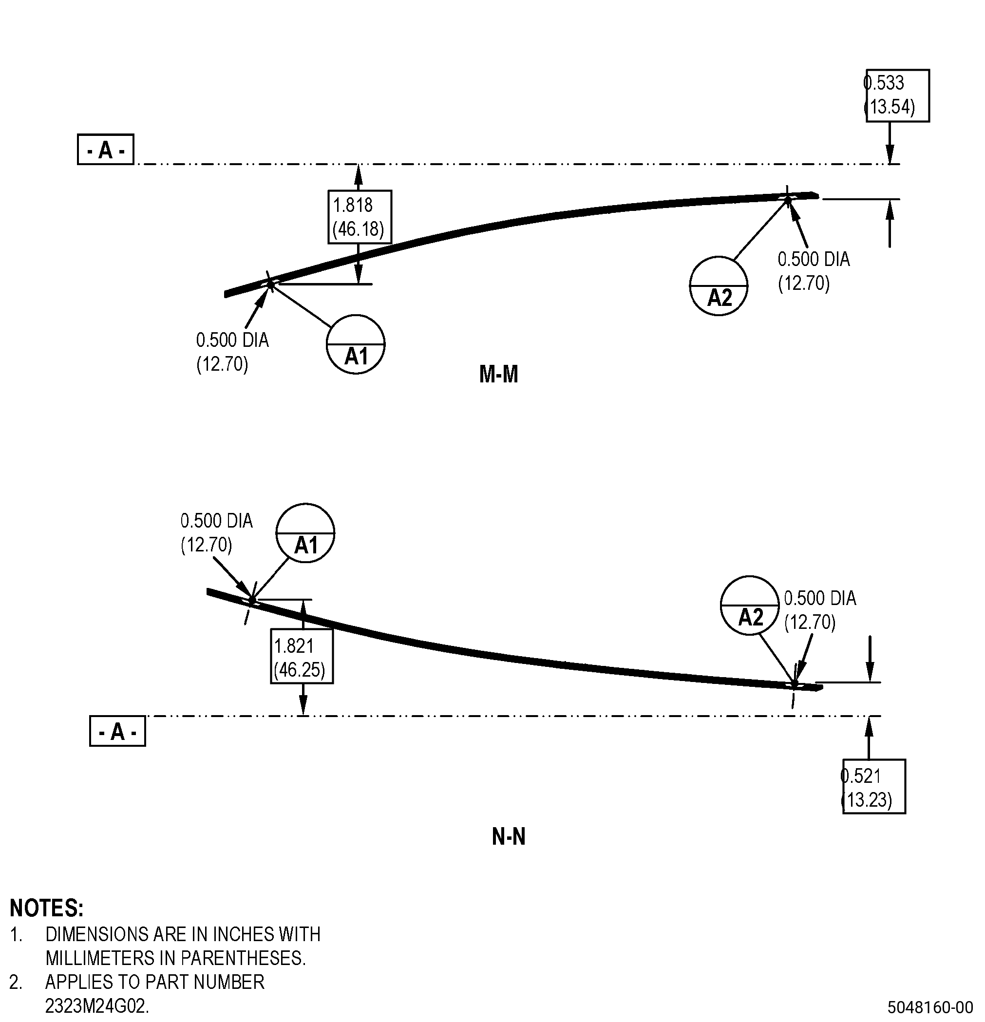
| A. | This procedure gives instructions to repair the lower and upper outlet guide vane panels (OGV panel) by installing a locally manufactured bushing (bushing) on the countersink holes. Refer to Figure 901. |
| B. | The following maximum repairable limits apply to this repair: |
| NOTE: |
|
| (5) | Visual Inspection. |
| (p) | Do an inspection of the OGV panels (01-160 , 72-21-00) (SIN 84402), (01-170 , 72-21-00) (SIN 84403), (01-380 , 72-21-00) (SIN 84502), and (01-390 , 72-21-00) (SIN 84503). Refer to Figure 807 and Figure 808. |
| 1 | Wear around the countersink holes of the OGV panels: |
| Maximum repairable limit: |
|
| C. | The subsequent table gives a list of the part numbers that are applicable to this repair. All part numbers are applicable to all paragraphs unless specified differently. |
|
|||||||||||||||||||||||||||||||||||||||||||||||||
| D. | Proprietary/Complex Process Statement. |
| (1) | None. |
| 2 . | Tools, Equipment, and Materials. |
| NOTE: |
|
| A. | Tools and Equipment. |
| (1) | Special Tools. None. |
| (2) | Standard Tools and Equipment. None. |
| (3) | Locally Manufactured Tools. None. |
| B. | Consumable Materials. |
|
| C. | Referenced Procedures. |
|
| D. | Expendable Parts. None. |
| E. | SPD Information. |
| (1) | Locally Manufactured SPD. |
|
| F. | Special Solutions. None. |
| G. | Test Specimens. None. |
| 3 . | Dimensional Information. |
| Subtask 72-21-99-220-066 |
| A. | Refer to Figure 901 for specified dimensions and locations. |
| NOTE: |
|
| NOTE: |
|
| 4 . | Setup Information. |
| None. |
| 5 . | Procedure. |
| Subtask 72-21-99-160-018 |
| A. | If necessary, clean the OGV panel. Refer to TASK 72-21-99-100-801 (72-21-99, CLEANING 001). |
| Subtask 72-21-99-350-001 |
| B. | Drill the damaged countersunk hole on the OGV panel to the in-process dimensions. Refer to TASK 70-00-03-800-004 (MACHINING DATA), Figure 901, Figure 902, and as follows: |
| (1) | Fully remove damage from the countersunk holes and as follows: |
| (a) | If there is a repair with this procedure in the countersunk holes, fully remove the damaged bushing and remaining adhesive from the countersunk hole. |
| (2) | Deleted. |
| (a) | Deleted. |
| Subtask 72-21-99-220-071 |
| C. | Do a dimensional inspection of the repair areas in the OGV panel. Refer to Figure 902 and as follows: |
| (1) | If one or more dimensions do not agree with the in-process limits, the OGV panel is not repairable with this procedure. |
| Subtask 72-21-99-160-019 |
| D. | Clean the OGV panel that you will repair. Refer to TASK 72-21-99-100-801 (72-21-99, CLEANING 001). |
| Subtask 72-21-99-350-007 |
| E. | Make a locally manufactured bushing. Refer to TASK 70-00-03-800-004 (MACHINING DATA), Figure 903, and as follows: |
| (1) | Use A286 alloy (AMS 5731/AMS 5732/AMS 5737/AMS 5525). |
| Subtask 72-21-99-350-008 |
| F. | Prepare the C01-156 epoxy paste adhesive as follows: |
| (1) | Make an estimate of the quantity of C01-156 epoxy paste adhesive that you will use. |
| (2) | Mix the C01-156 epoxy paste adhesive in a clean metal or non-coated paper container in the ratio that follows: |
| (a) | Part A (resin) - 100 parts by weight. |
| (b) | Part B (catalyst) - 20 parts by weight. |
| (3) | Mix part A and part B until no streaks of the two components come into view and as follows: |
| (a) | Use the C01-156 epoxy paste adhesive in 75 minutes or less. |
| Subtask 72-21-99-350-009 |
| G. | Apply the C01-156 epoxy paste adhesive to the surfaces on the OGV panel and the new bushing that you will bond. Refer to Figure 904. |
| Subtask 72-21-99-350-010 |
| H. | Install the new bushing in the OGV panel. Refer to Figure 904 and as follows: |
| (1) | Apply contact pressure to the new bushing and the OGV panel. |
| (2) | Cure in accordance with manufacturer instructions and as follows: |
| (a) | Make sure that you do not cure to more than 200°F (93°C). |
| Subtask 72-21-99-350-011 |
| I. | Blend the OGV panel. Refer to TASK 70-42-00-350-002 (BLENDING AND REMOVAL OF HIGH METAL PROCEDURES), and as follows: |
| (1) | Blend the OGV panel to the adjacent contour. |
| (2) | Remove high metal and unwanted epoxy paste adhesive. |
| Subtask 72-21-99-220-072 |
| J. | Do a visual inspection of the bonded joint in the OGV panel as follows: |
| (1) | Use 10X magnification to make sure that the edge of the bonded joint shows a constant bead of adhesive with no linear indications or discontinuities. |
| NOTE: |
|
| (2) | Do an inspection for disbond and as follows: |
| (a) | If the new bushing is disbonded, do this repair again. |