| GENX-1B CLEANING,INSPECTION,AND REPAIR MANUAL | Dated: 03/31/2012 | |
| CIR 72-22-41 , REPAIR 001 | ||
| BOOSTER SPOOL - REPAIR - SHANK NUT REPLACEMENT | ||
| GENX-1B CLEANING,INSPECTION,AND REPAIR MANUAL | Dated: 03/31/2012 | |
| CIR 72-22-41 , REPAIR 001 | ||
| BOOSTER SPOOL - REPAIR - SHANK NUT REPLACEMENT | ||
| * * * FOR ALL |
| TASK 72-22-41-300-801 |
| 1 . | Repair for the Booster Spool. |
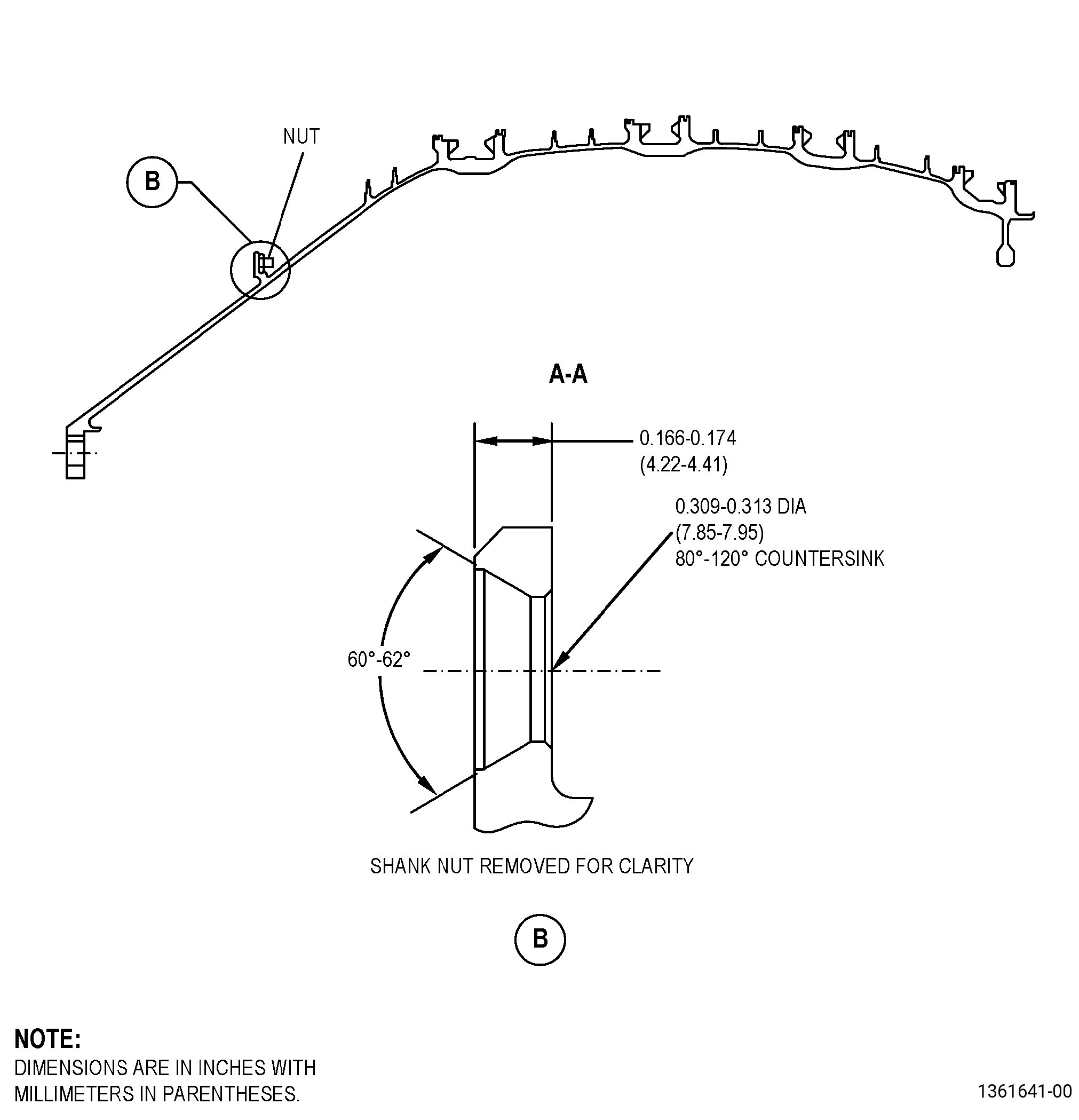
| A. | This procedure gives instructions to repair the booster spool (spool) by replacing damaged shank nuts (nuts). Refer to Figure 901. |
| B. | The following maximum repairable limits apply to this repair: |
| NOTE: |
|
| NOTE: |
|
| (4) | Visual Inspection. |
| (h) | Do an inspection of each self-locking shank nut (nut) for: |
| 1 | Loss of self-locking quality (0.250-28UNJF): |
| Maximum repairable limit: |
|
| 2 | Damaged threads: |
| Maximum repairable limit: |
|
| 3 | Looseness: |
| Maximum repairable limit: |
|
| 4 | Cracks in the shank: |
| Maximum repairable limit: |
|
| 5 | Missing nuts: |
| Maximum repairable limit: |
|
| C. | The subsequent table gives a list of the part numbers that are applicable to this repair. All part numbers are applicable to all paragraphs unless specified differently. |
|
|||||||||||||||||||||||
| D. | Proprietary/Complex Process Statement. |
| (1) | None. |
| 2 . | Tools, Equipment, and Materials. |
| NOTE: |
|
| A. | Tools and Equipment. |
| (1) | Special Tools. None. |
| (2) | Standard Tools and Equipment. |
|
| (3) | Locally Manufactured Tools. |
|
| B. | Consumable Materials. |
| C. | Referenced Procedures. |
|
| D. | Expendable Parts. None. |
| E. | SPD Information. |
|
| F. | Special Solutions. None. |
| G. | Test Specimens. None. |
| 3 . | Dimensional Information. |
| Subtask 72-22-41-220-057 |
| A. | Refer to Figure 901 for specified dimensions and locations. |
| NOTE: |
|
| NOTE: |
|
| 4 . | Setup Information. |
| Subtask 72-22-41-350-001 |
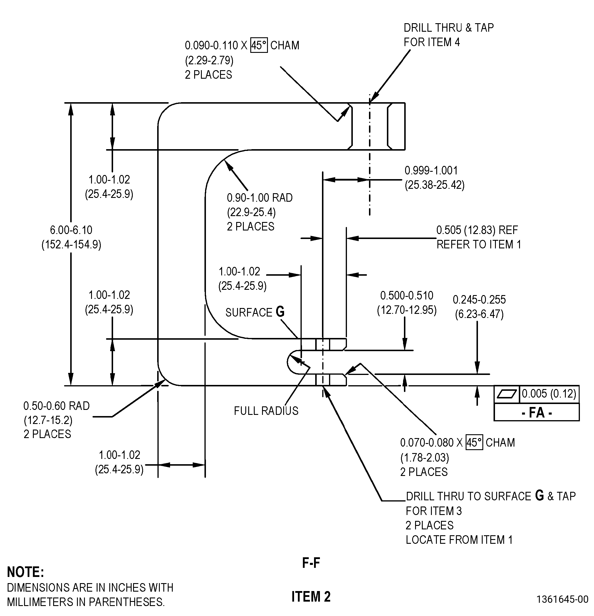
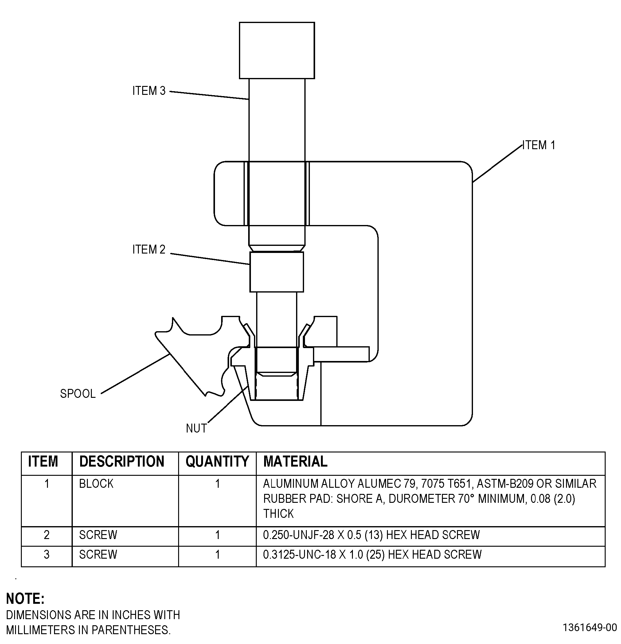
| A. | Set-up to remove the damaged nuts from the spool. Refer to Figure 904 and as follows: |
| Subtask 72-22-41-930-001 |
| (1) | If necessary, make an extracting tool. Refer to Figure 903. |
| Subtask 72-22-41-350-005 |
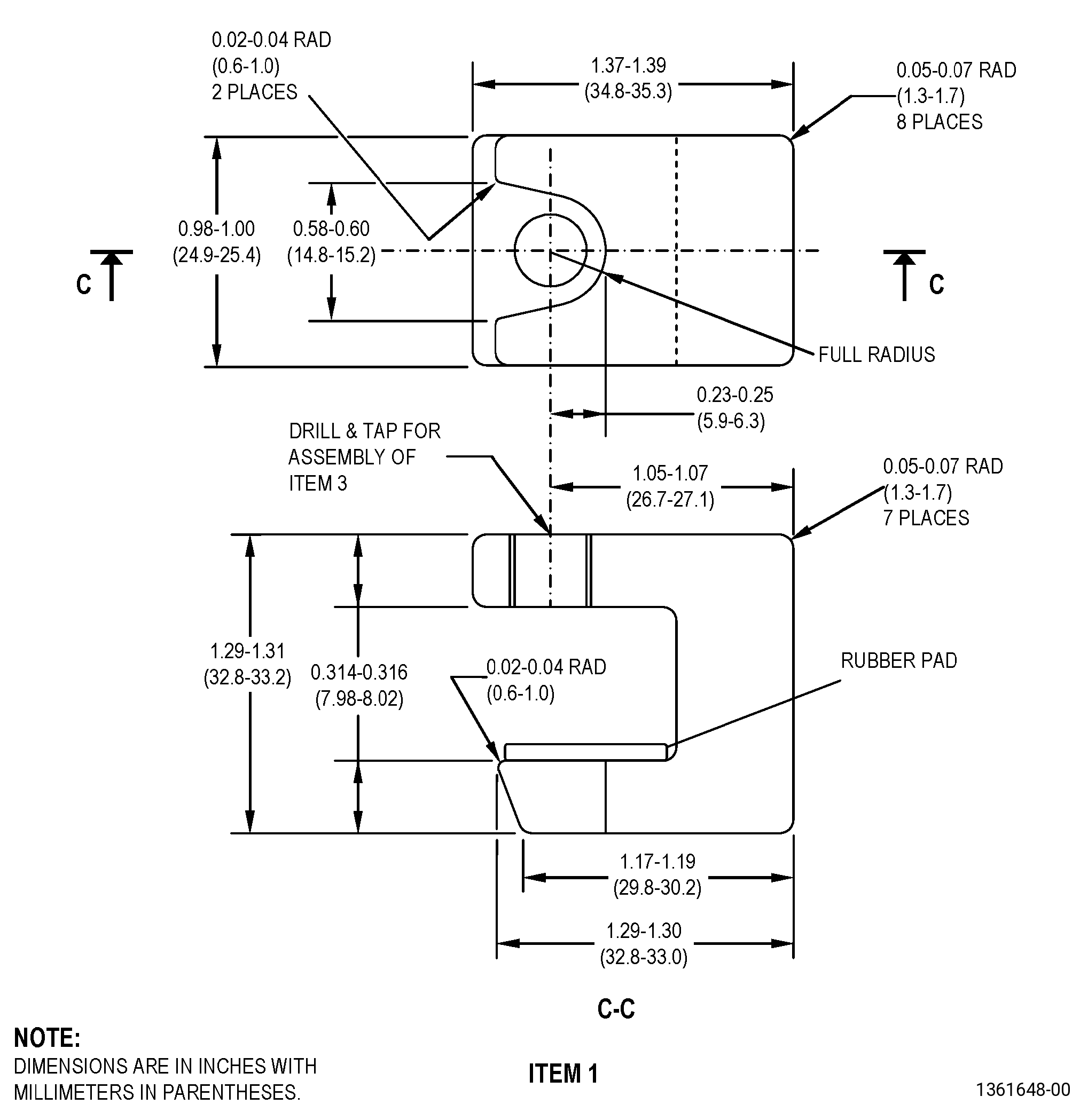
| (2) | Install a screw (item 2) into the nut. Tighten the screw (item 2) so that approximately three threads are in the nut. |
| (3) | Install the block (item 1) so that the rubber pad is on the same side as the nut. |
| (4) | Make sure that the flange is seated flat on the rubber pad with no clearance in between. |
| (5) | Install the screw (item 3) into the block (item 1) so that the end of the screw (item 3) touches the head of the screw (item 2). |
| Subtask 72-22-41-350-006 |
| B. | Set-up to install the new nuts. Refer to Figure 905 and as follows: |
| Subtask 72-22-41-930-002 |
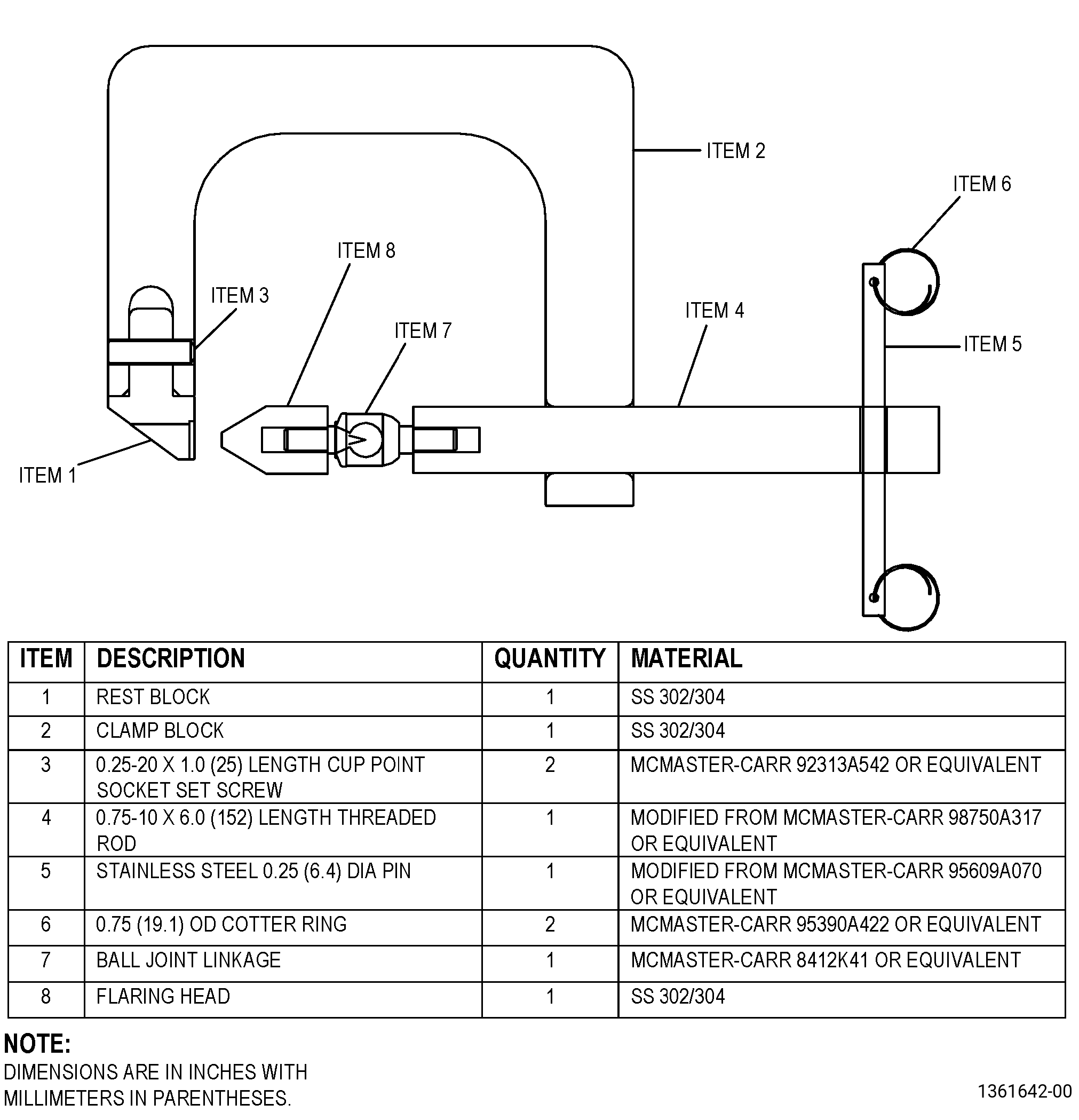
| (1) | If necessary, make the flaring tool. Refer to Figure 902. |
| Subtask 72-22-41-350-007 |
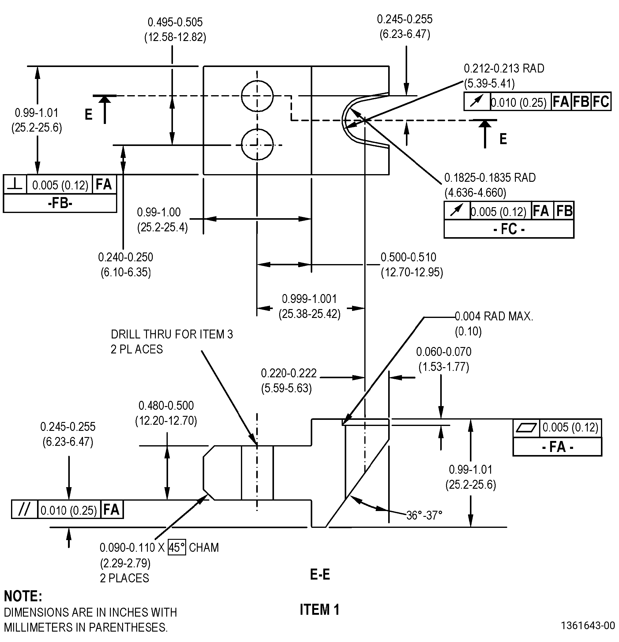
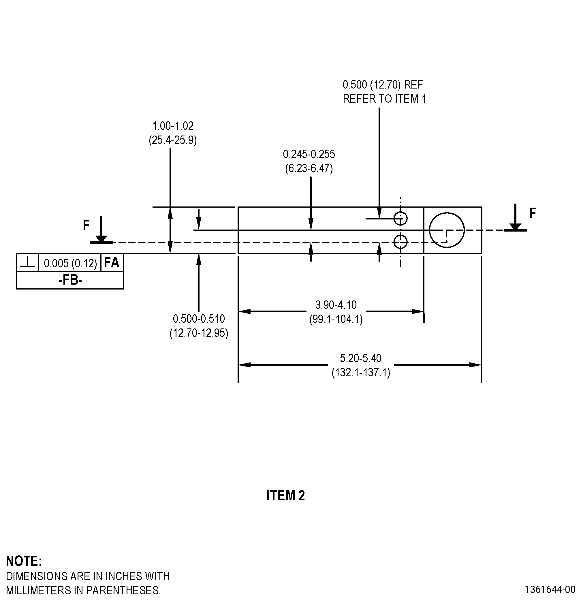
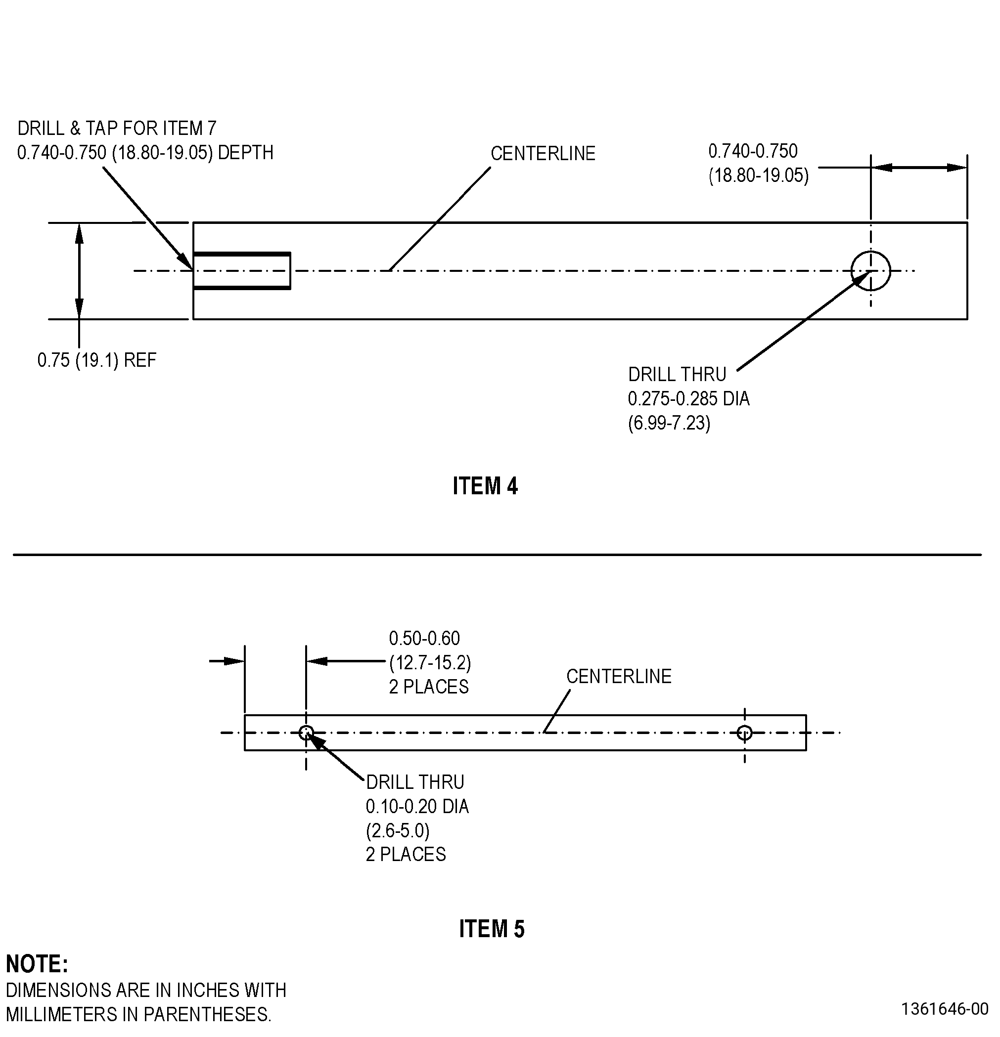
| (2) | Assemble the rest block (item 1), clamp block (item 2), and set screws (item 3) together into a holder fixture. |
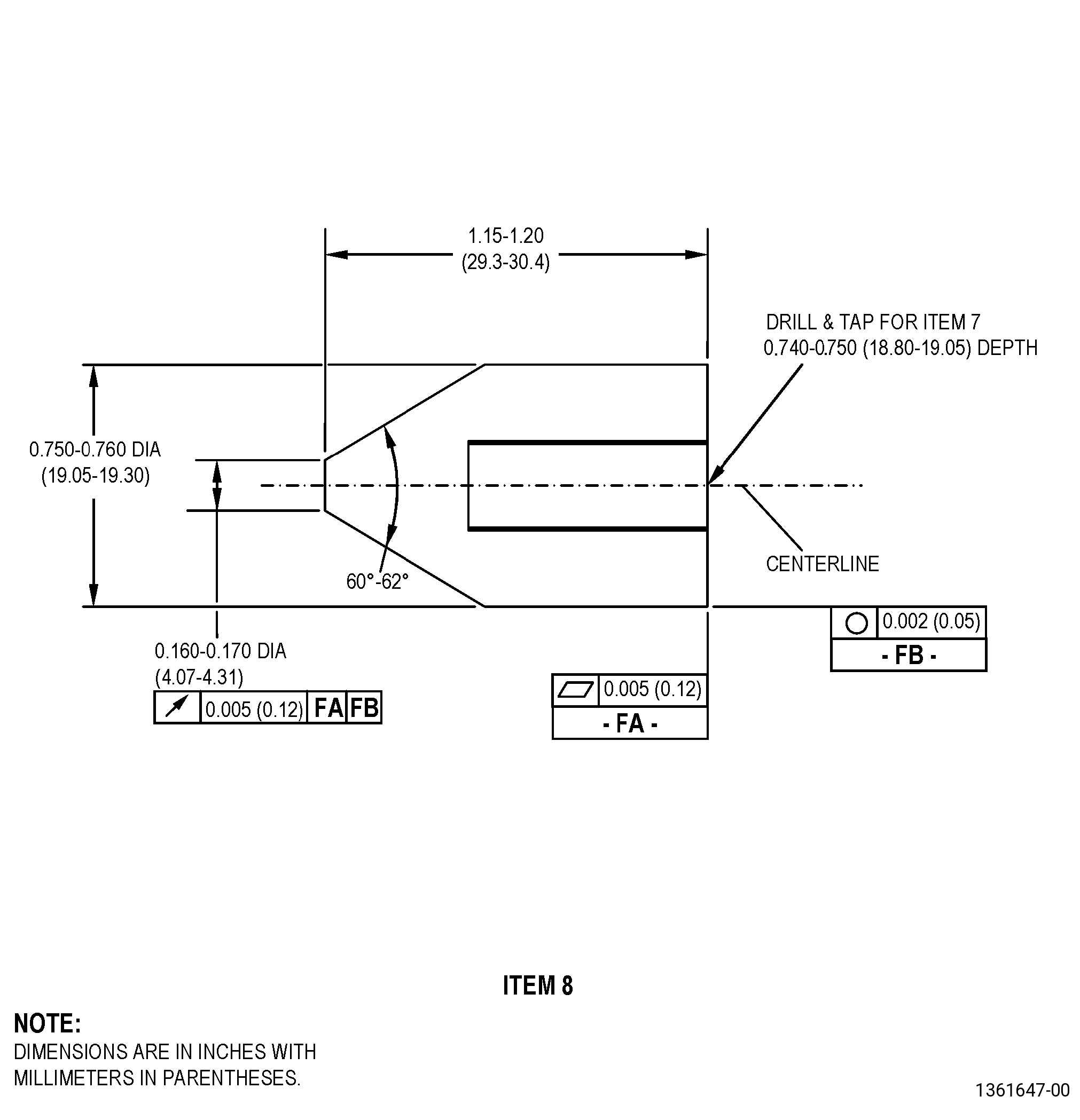
| (3) | Assemble the rod (item 4), pin (item 5), cotter ring (item 6), ball joint linkage (item 7), and flaring head (item 8) together into a flaring tool. |
| (4) | Install the holder fixture (item 1, 2, 3) onto the nut. |
| (5) | Install the flaring tool (item 4, 5, 6, 7, 8) into the holder fixture (item 1, 2, 3). |
| (6) | Make the centerline of the flaring tool align with the centerline of the nut. |
| 5 . | Procedure. |
| Subtask 72-22-41-350-002 |
| CAUTION: |
|
| A. | Remove the damaged nuts from the spool. Refer to TASK 70-48-13-350-024 (SHANK NUT REPAIR) and as follows: |
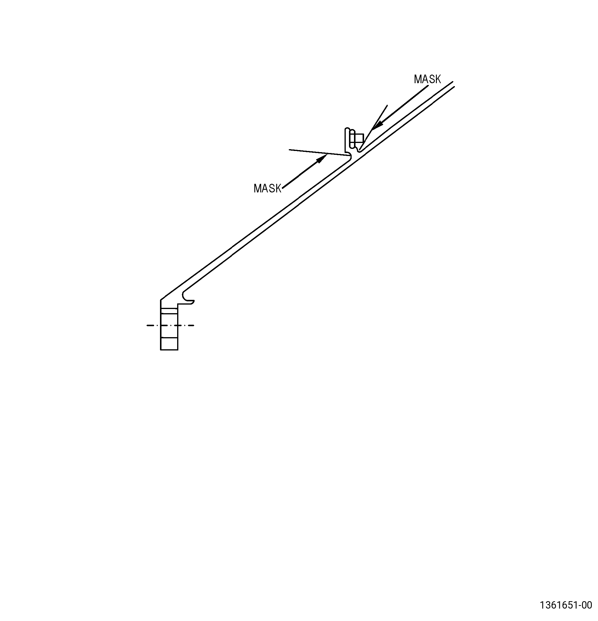
| (1) | Apply C10-021 masking to the spool cone surface adjacent to the nut. Refer to Figure 906. |
| (2) | Set-up to remove the nut from the spool. Refer to Subtask 72-22-41-350-001 (paragraph 4.A.), Setup Information. |
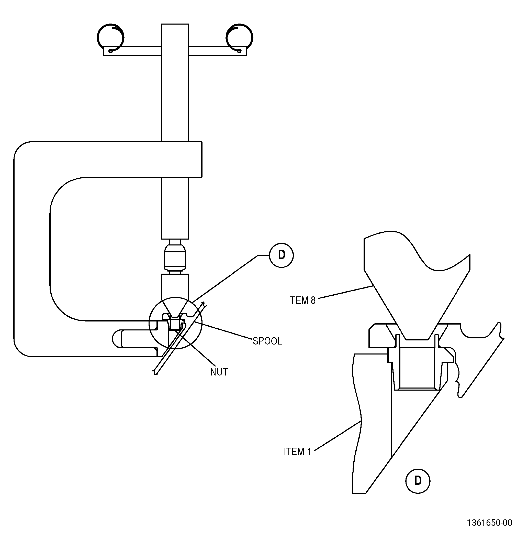
| (3) | Use a spanner to tighten the screw (item 3) so that it pushes the head of the screw (item 2) down into the flange. |
| (4) | Continue to tighten the screw (item 3) until the nut is pushed out of the flange. |
| (5) | Remove the extracting tool and masking. |
| Subtask 72-22-41-110-006 |
| WARNING: |
|
| (6) | Clean the exposed holes with C04-035 isopropyl alcohol and a C10-182 lint-free cloth. |
| Subtask 72-22-41-200-003 |
| (7) | Do an inspection of the holes for nicks/burrs, and distortion/damage caused by the removal process. Refer to TASK 72-22-41-200-805 (72-22-41, INSPECTION 001), Figure 901, and as follows: |
| (a) | If the holes do not agree with the dimensions in Figure 901, the spool is not repairable. |
| Subtask 72-22-41-350-003 |
| B. | If necessary, blend the holes and surrounding areas to remove burrs and sharp edges. Refer to TASK 70-42-00-350-002 (BLENDING AND REMOVAL OF HIGH METAL PROCEDURES) and as follows: |
| (1) | Blend to remove the burrs and high metal. Smooth to adjacent parent metal contour. High metal is not permitted. |
| (2) | Make sure the flange thickness at the blended areas agree with the dimensions in Figure 901. |
| Subtask 72-22-41-110-005 |
| C. | Etch the holes. Refer to TASK 70-24-00-110-033 (ETCHING PROCEDURES FOR FLUORESCENT-PENETRANT INSPECTION), TASK 70-24-01-110-034 (SWAB ETCHING PROCEDURE), and as follows: |
| (1) | Use Class B etchant. |
| Subtask 72-22-41-200-001 |
| D. | Do an inspection of the holes. Refer to TASK 70-32-00-200-002 (INDIRECT INSPECTION METHODS), TASK 70-32-03-230-002 (SPOT-FLUORESCENT-PENETRANT INSPECTION), and as follows: |
| (1) | Use Class G penetrant. |
| (2) | Indications less than 0.015 inch (0.38 mm) are permitted. |
| (3) | Indications are not permitted in fillets. |
| (4) | Indications must not cross corners. |
| (5) | Linear indications are not permitted. |
| NOTE: |
|
| Subtask 72-22-41-350-004 |
| E. | Install the new nut (1710M49P01 ) in the spool flange. Refer to TASK 70-48-13-350-024 (SHANK NUT REPAIR), Figure 902, and as follows: |
| (1) | Set-up to install the nut. Refer to Subtask 72-22-41-350-006 (paragraph 4.B.), Setup Information and as follows: |
| (a) | The flaring tool must support the base of the nut during the whole flaring process. |
| Subtask 72-22-41-640-001 |
| (2) | Apply C02-008 lubricant on the flaring tip of the flaring tool to decrease the risk of cracking in the nut shank. |
| (3) | Turn the flaring tool so that it moves towards the nut and flares the nut shank. |
| Subtask 72-22-41-220-058 |
| CAUTION: |
|
| (4) | Do a visual inspection of the flared shank of the nut as follows: |
| (a) | Damage to the plating on the flared surface is permitted. |
| (b) | The nut shank must be below the flange surface. |
| (c) | Under hand pressure, no movement is permitted in the shank nut after swaging. |
| (d) | Rotation of the nut up to the machined shoulder of the flange is permitted. |
| (e) | Damage to the shank nut caused by the flaring tool is permitted up to a maximum of 0.003 inch (0.07 mm) in depth. |
| Subtask 72-22-41-200-002 |
| F. | Do an inspection of the flared shank of the nut. Refer to TASK 70-32-00-200-002 (INDIRECT INSPECTION METHODS), TASK 70-32-03-230-002 (SPOT-FLUORESCENT-PENETRANT INSPECTION), and as follows: |
| (1) | Use Class A penetrant. |
| (2) | Linear indications are not permitted. |
| NOTE: |
|