| GENX-1B CLEANING,INSPECTION,AND REPAIR MANUAL | Dated: 12/30/2019 | |
| CIR 72-31-41 , REPAIR 003 | ||
| HIGH PRESSURE COMPRESSOR STAGE 1 BLISK - REPAIR - GENERAL BLEND REPAIR | ||
| GENX-1B CLEANING,INSPECTION,AND REPAIR MANUAL | Dated: 12/30/2019 | |
| CIR 72-31-41 , REPAIR 003 | ||
| HIGH PRESSURE COMPRESSOR STAGE 1 BLISK - REPAIR - GENERAL BLEND REPAIR | ||
| * * * FOR ALL |
| TASK 72-31-41-300-802 |
| 1 . | General Blend Repair. |
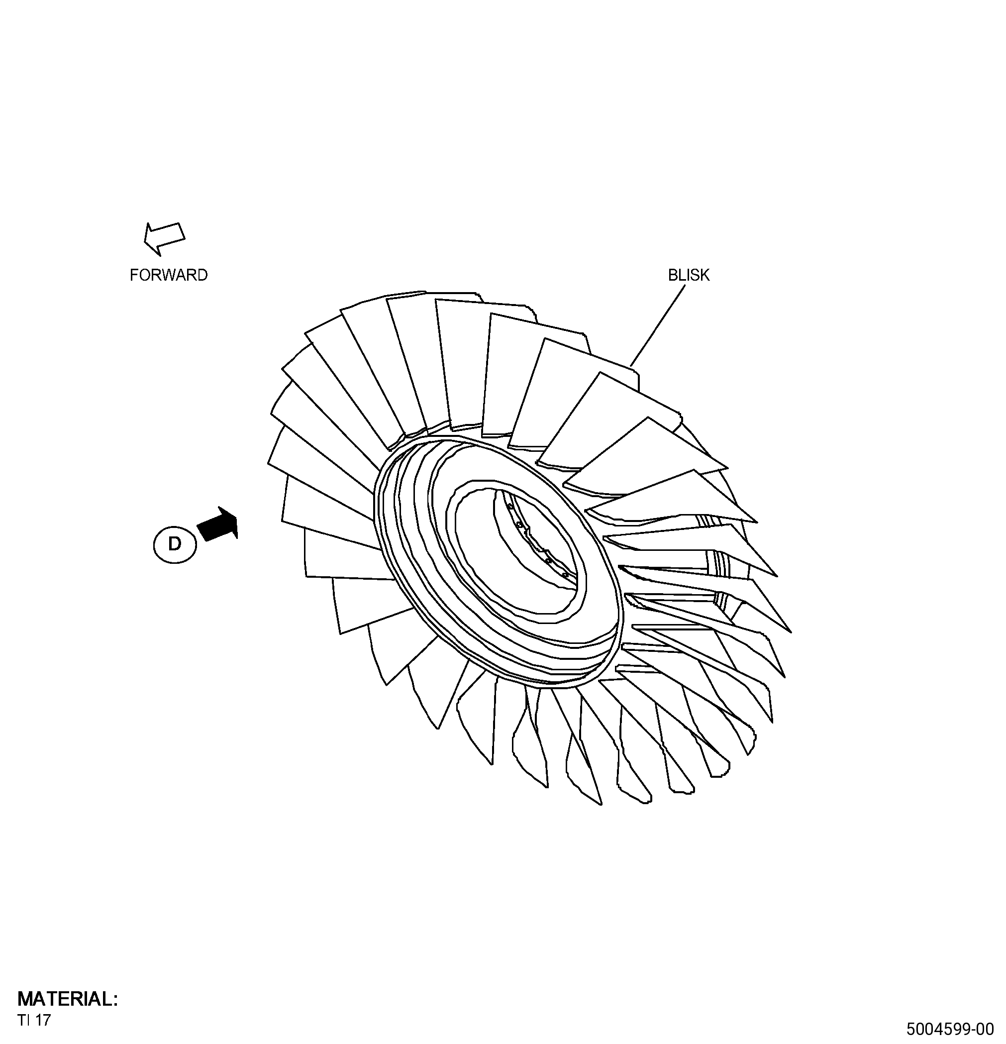
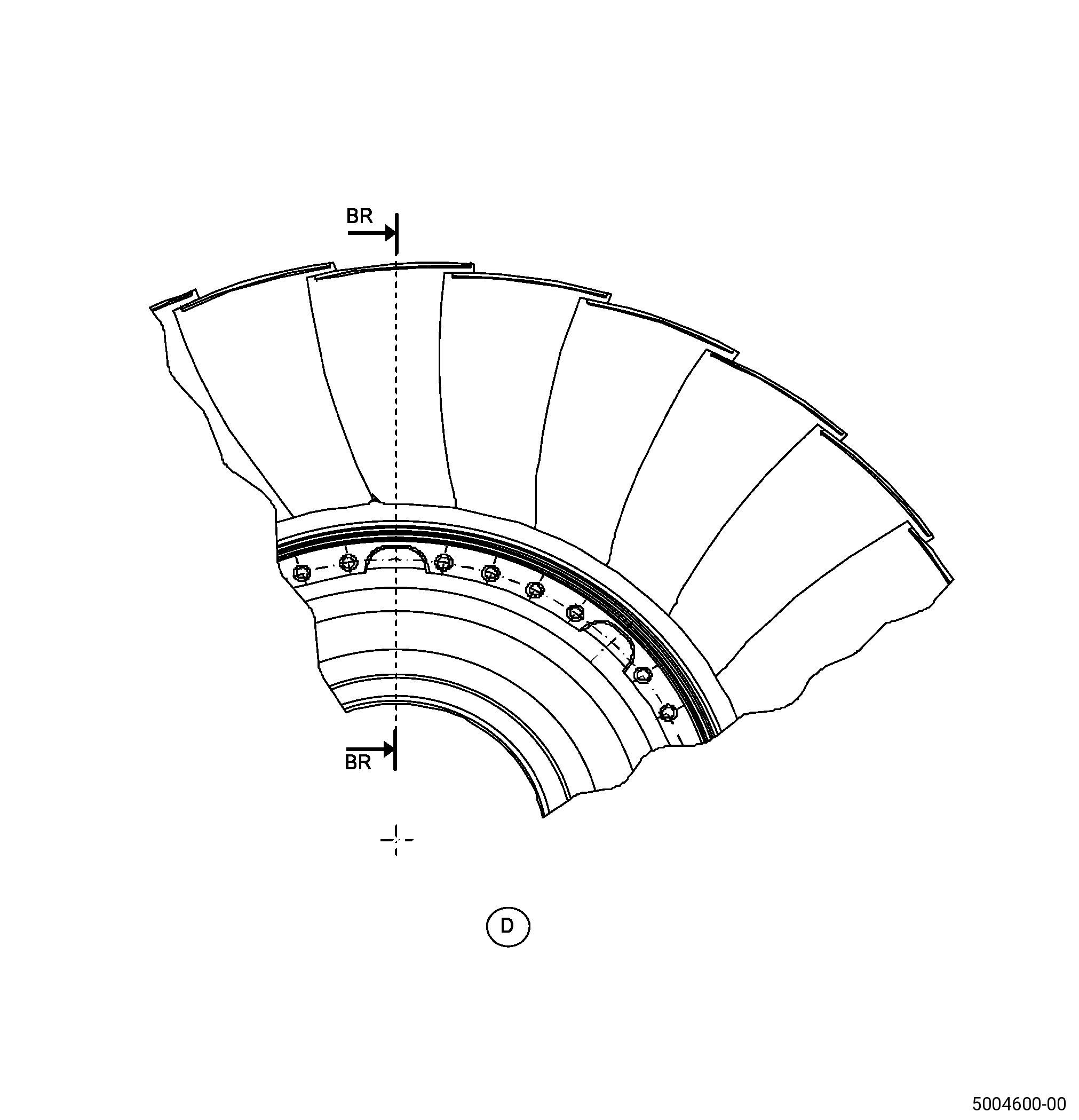
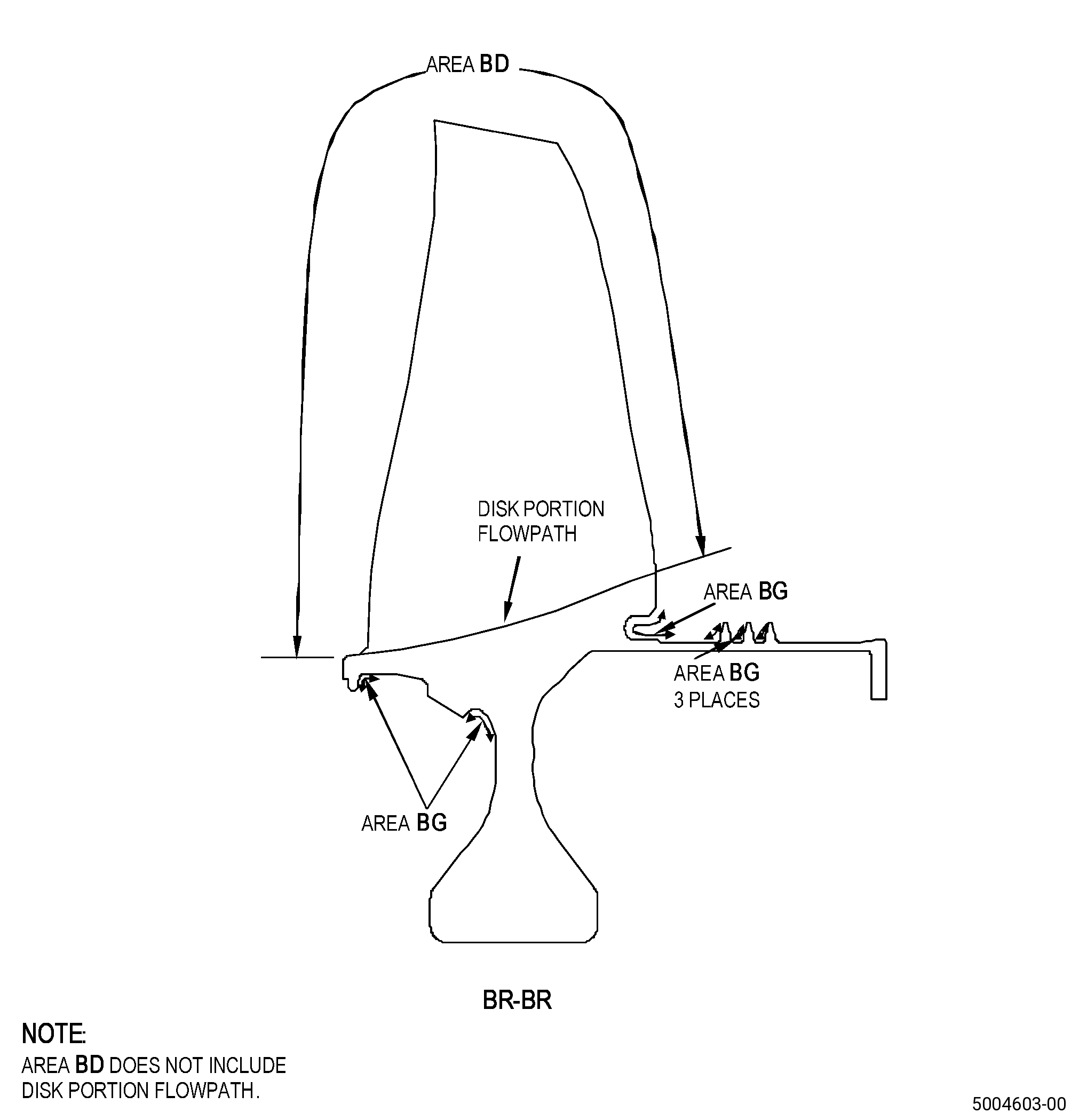
| A. | This procedure gives instructions to repair the high pressure compressor stage 1 blisk (blisk) by blending the seal teeth. Refer to Figure 901. |
| B. | The following maximum repairable limits apply to this repair: |
| NOTE: |
|
| NOTE: |
|
| (5) | Visual Inspection. |
| (f) | Do an inspection of the flowpath surface of the blisk (does not include root fillet) for: |
| 1 | Nicks, dents, pits (if not corrosion related), and scratches: |
| Maximum Repairable Limit: |
|
| (i) | Do an inspection of the flange for: |
| 2 | Nicks, dents, pits (if not corrosion related), and scratches on bolt pads: |
| Maximum Repairable limit: |
|
| 4 | Nicks, dents, pits (if not corrosion related), and scratches on diameter AY: |
| Maximum Repairable limit: |
|
| 5 | Nicks, dents, pits (if not corrosion related), and scratches on surface AX: |
| Maximum Repairable limit: |
|
| (k) | Do an inspection of the aft flange scallop (8 locations) for: |
| 1 | Nicks, dents, pits (if not corrosion related), or scratches on the scallop surface: |
| Maximum Repairable limit: |
|
| 2 | Nicks, dents, pits (if not corrosion related), or scratches on the scallop chamfers (forward and aft sides): |
| Maximum Repairable limit: |
|
| (l) | Do an inspection of the disk bore, hub faces, and web for: |
| 1 | Nicks, dents, pits (if not corrosion related), or scratches on the disk bore: |
| Maximum Repairable limit: |
|
| 2 | Nicks, dents, pits (if not corrosion related), or scratches on hub faces: |
| Maximum Repairable limit: |
|
| 3 | Nicks, dents, pits (if not corrosion related), or scratches on webs and web transitions: |
| Maximum Repairable limit: |
|
| (m) | Do an inspection of the damper interface for: |
| 1 | Nicks, dents, pits (if not corrosion related), or scratches: |
| Maximum Repairable limit: |
|
| (n) | Do an inspection of the seal teeth for: |
| 1 | Nicks, dents, pits (if not corrosion related), or scratches: |
| Maximum Repairable limit: |
|
| • |
|
| • |
|
| • |
|
| • |
|
| • |
|
| (o) | Do an inspection of the aft flange ID fillet for: |
| 1 | Marks, nicks, dents, and scratches: |
| Maximum Repairable limit: |
|
| (p) | Do an inspection of all other areas on the disk portion of the part (does not include airfoils or flowpath) for: |
| 1 | Nicks, dents, pits (if not corrosion related), or scratches: |
| Maximum Repairable limit: |
|
| C. | The subsequent table gives a list of the part numbers that are applicable to this repair. All part numbers are applicable to all paragraphs unless specified differently. |
|
|||||||||||||||||||||||
| D. | Proprietary/Complex Process Statement. |
| (1) | None. |
| 2 . | Tools, Equipment, and Materials. |
| NOTE: |
|
| A. | Tools and Equipment. |
| (1) | Special Tools. None. |
| (2) | Standard Tools and Equipment. None. |
| (3) | Locally Manufactured Tools. None. |
| B. | Consumable Materials. |
|
| C. | Referenced Procedures. |
| D. | Expendable Parts. None. |
| E. | SPD Information. |
| (1) | Locally Manufactured SPD. None. |
| F. | Special Solutions. None. |
| G. | Test Specimens. None. |
| 3 . | Dimensional Information. |
| Subtask 72-31-41-220-079 |
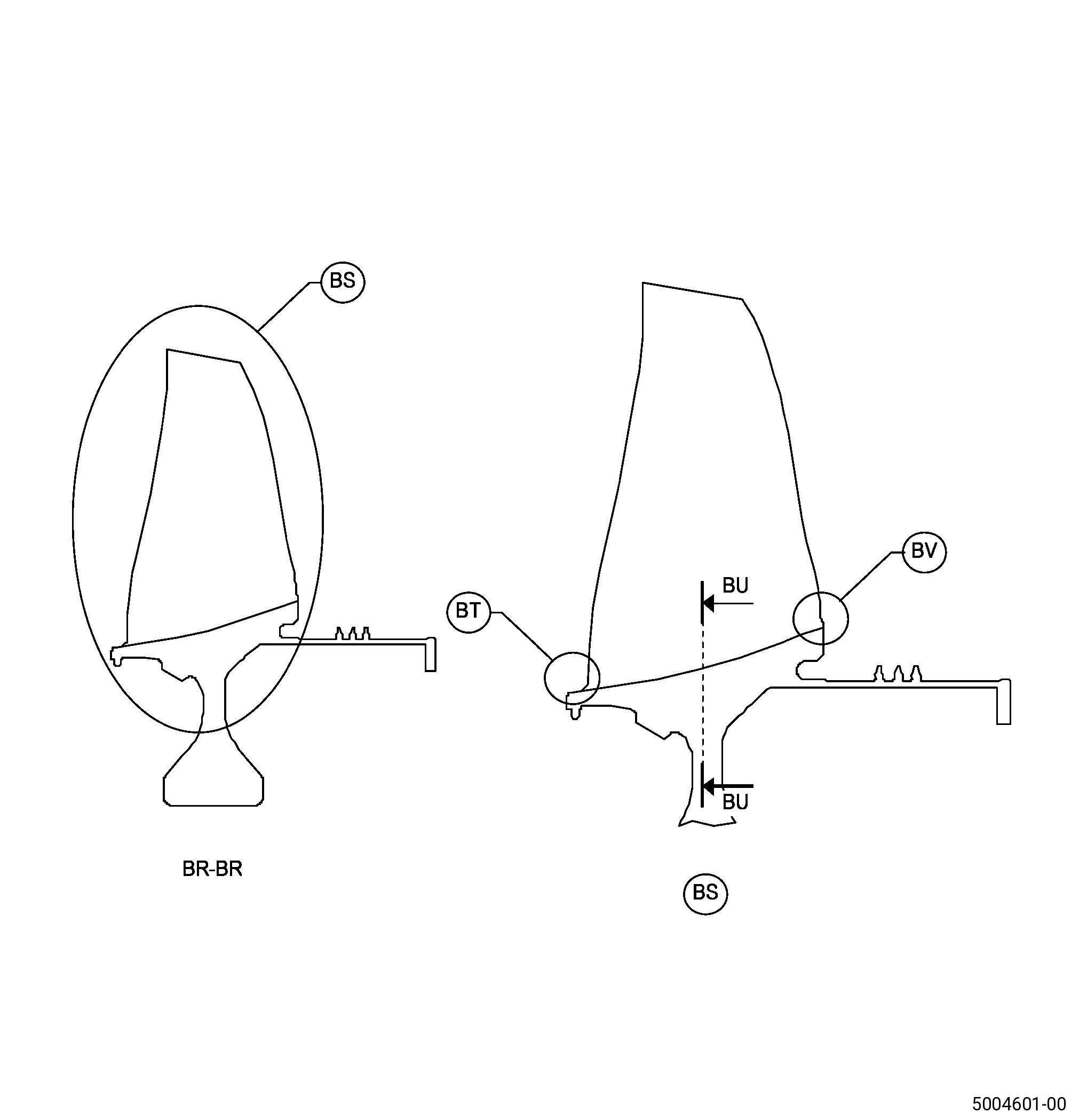
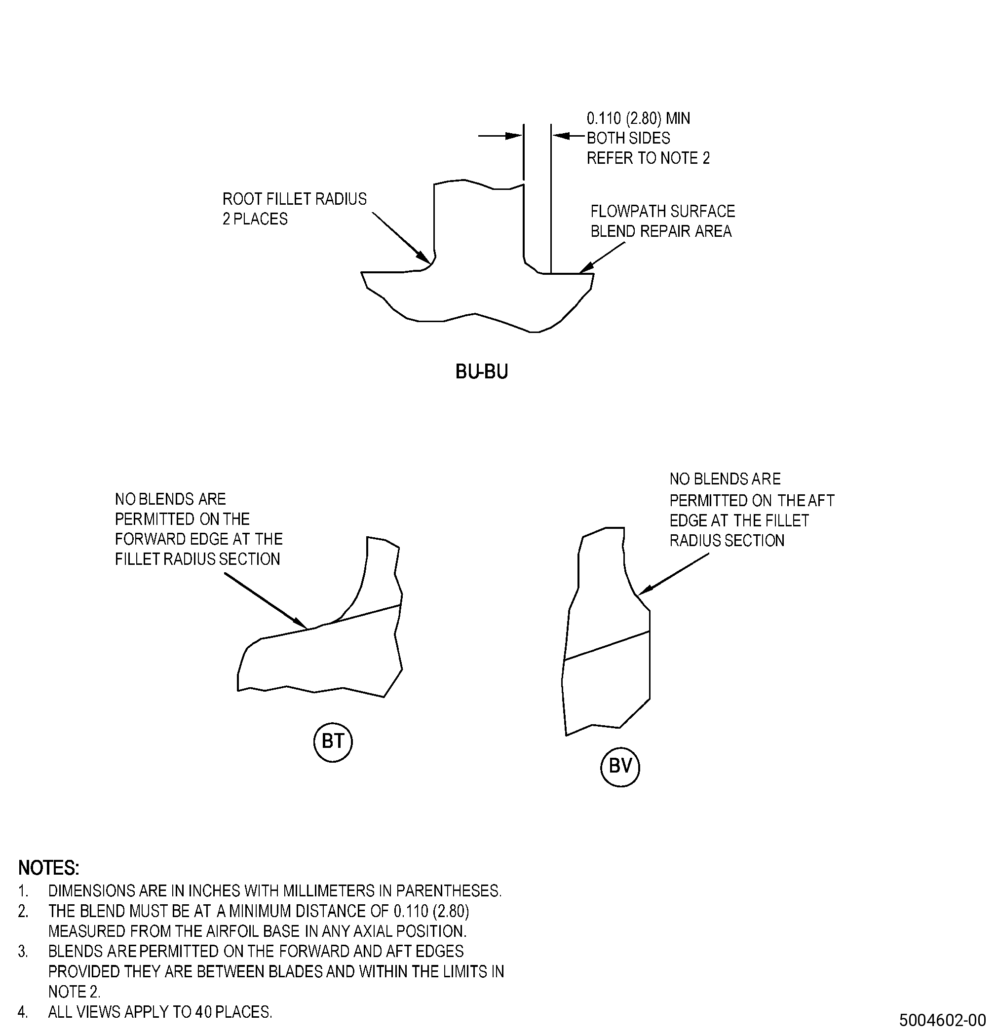
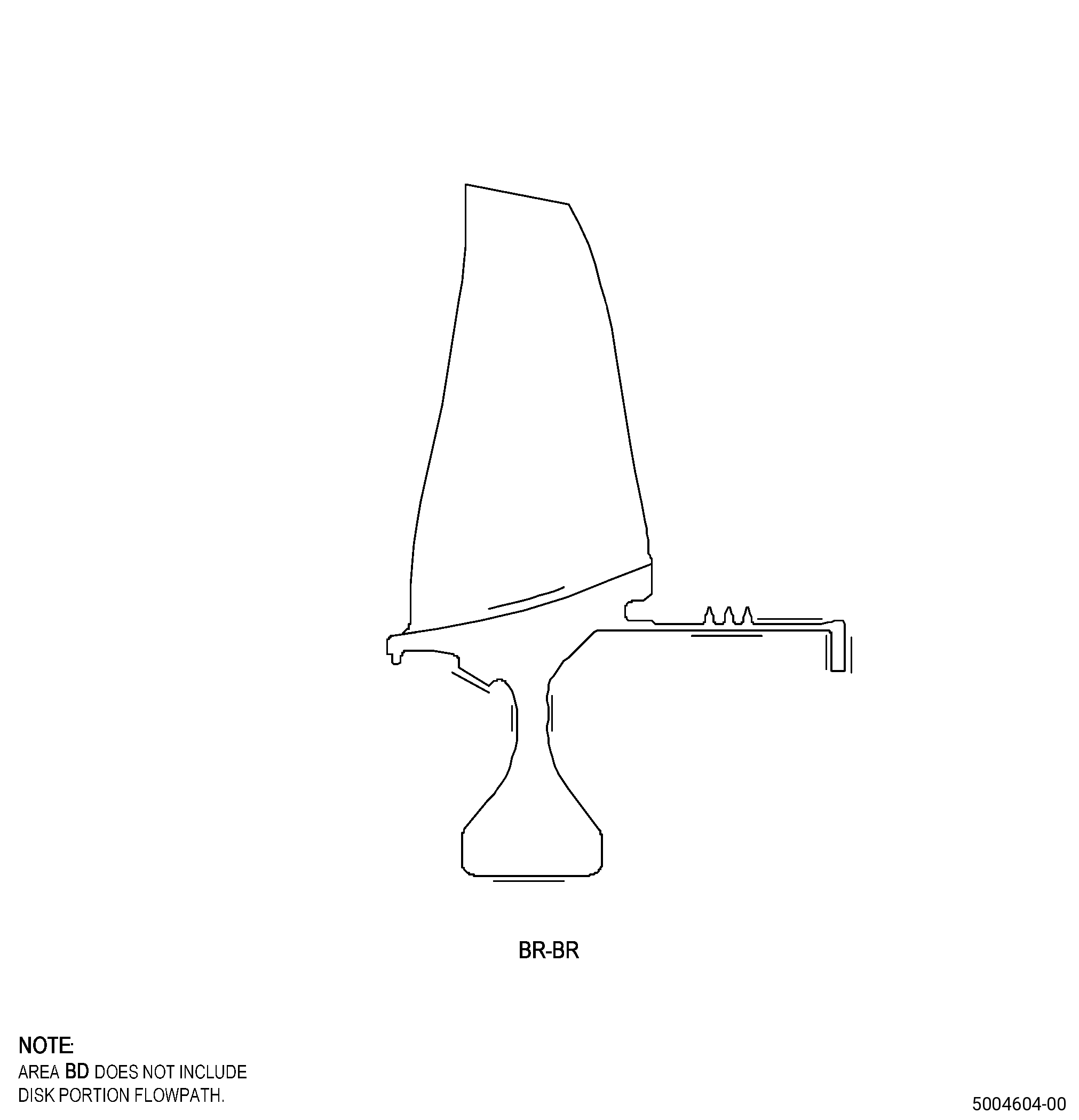
| A. | Refer to Figure 901, Figure 902, and Figure 903 for specified dimensions and locations. |
| NOTE: |
|
| NOTE: |
|
| 4 . | Setup Information. |
| None. |
| 5 . | Procedure. |
| Subtask 72-31-41-160-003 |
| A. | If necessary, clean the blisk. Refer to TASK 70-21-00-110-051 (CHEMICAL CLEANING) and TASK 70-21-03-160-001 (CLEANING METHOD NO. 3 - STEAM CLEANING). |
| Subtask 72-31-41-220-074 |
| B. | Do a visual inspection of the blisk. Refer to TASK 72-31-41-200-801 (72-31-41, INSPECTION 001). |
| Subtask 72-31-41-350-003 |
| C. | Blend the blisk damaged areas. Refer to TASK 70-42-00-350-002 (BLENDING AND REMOVAL OF HIGH METAL PROCEDURES), Figure 901, Figure 902, and as follows: |
| (1) | Make sure that you blend only the permitted blisk areas, refer to TASK 72-31-41-200-801 (72-31-41, INSPECTION 001). |
| (2) | Deleted. |
| Subtask 72-31-41-160-004 |
| D. | Clean the blisk blended areas. Refer to TASK 70-21-00-110-051 (CHEMICAL CLEANING) and TASK 70-21-03-160-001 (CLEANING METHOD NO. 3 - STEAM CLEANING). |
| Subtask 72-31-41-110-005 |
| E. | Etch the blisk blended areas. Refer to TASK 70-24-00-110-033 (ETCHING PROCEDURES FOR FLUORESCENT-PENETRANT INSPECTION) , TASK 70-24-01-110-034 (SWAB ETCHING PROCEDURE) , and as follows: |
| (1) | Use Class B etchant. |
| Subtask 72-31-41-230-004 |
| F. | Alternative Procedure Available. Do an inspection of the blisk blended areas. Refer to TASK 70-32-00-200-002 (INDIRECT INSPECTION METHODS), TASK 70-32-02-230-001 (FLUORESCENT PENETRANT INSPECTION), and as follows: |
| (1) | Use Class G penetrant. |
| (2) | Indications more than 0.015 inch (0.38 mm) are not permitted. |
| (3) | Linear indications are not permitted. |
| NOTE: |
|
| (4) | Indications which cross corners are not permitted. |
| Subtask 72-31-41-230-005 |
| F.A. | Alternative Procedure. Do an inspection of the blisk blended areas. Refer to TASK 70-32-00-200-002 (INDIRECT INSPECTION METHODS), TASK 70-32-03-230-002 (SPOT-FLUORESCENT-PENETRANT INSPECTION), and as follows: |
| (1) | Use Class G penetrant. |
| (2) | Indications more than 0.015 inch (0.38 mm) are not permitted. |
| (3) | Linear indications are not permitted. |
| NOTE: |
|
| (4) | Indications which cross corners are not permitted. |
| Subtask 72-31-41-140-001 |
| WARNING: |
|
| G. | Polish the blisk to remove the effects of the etching procedure as follows: |
| (1) | Use C10-010 abrasive cloth. |
| Subtask 72-31-41-380-002 |
| H. | Peen the blisk repair areas. Refer to TASK 70-47-01-380-016 (SHOTPEENING), Figure 901, Figure 903, and as follows: |
| (1) | Use C04-166 CCW14 steel shot. |
| (2) | Peen the blisk to an intensity of 0.006-0.012N. |
| (3) | Ricochet peening is permitted in the blisk areas BG. |
| (4) | Coverage must be a minimum of 125 percent. |
| (5) | Overspray is not permitted in the blisk area BD. |
| (6) | Do an inspection of the intensity in all the blisk repaired areas with C10-205 Almen test strips and an Almen test strip holder. |
| Subtask 72-31-41-160-005 |
| I. | Clean the blisk repaired areas. Refer to TASK 70-21-00-110-051 (CHEMICAL CLEANING) and TASK 70-21-03-160-001 (CLEANING METHOD NO. 3 - STEAM CLEANING). |
| Subtask 72-31-41-220-075 |
| J. | Do a visual inspection of the blisk repair areas. Refer to TASK 72-31-41-200-801 (72-31-41, INSPECTION 001). |