| COMMERCIAL ENGINE STANDARD PRACTICES MANUAL | Dated: 11/10/2020 | |
| SPM 70-47-01 SHOTPEENING | ||
| COMMERCIAL ENGINE STANDARD PRACTICES MANUAL | Dated: 11/10/2020 | |
| SPM 70-47-01 SHOTPEENING | ||
| TASK 70-47-01-380-016 |
| 1 . | General. |
| A. | Shotpeening is a process which utilizes metal shot, glass beads, or ceramic beads to beneficially condition a component surface. In effect, this action forms compressive residual stresses at the surface, thereby increasing its resistance to stress corrosion and cyclic fatigue. The media composition and size, intensity, and coverages required for the surface conditioning of specific parts are stipulated in the Engine/Shop Manual. |
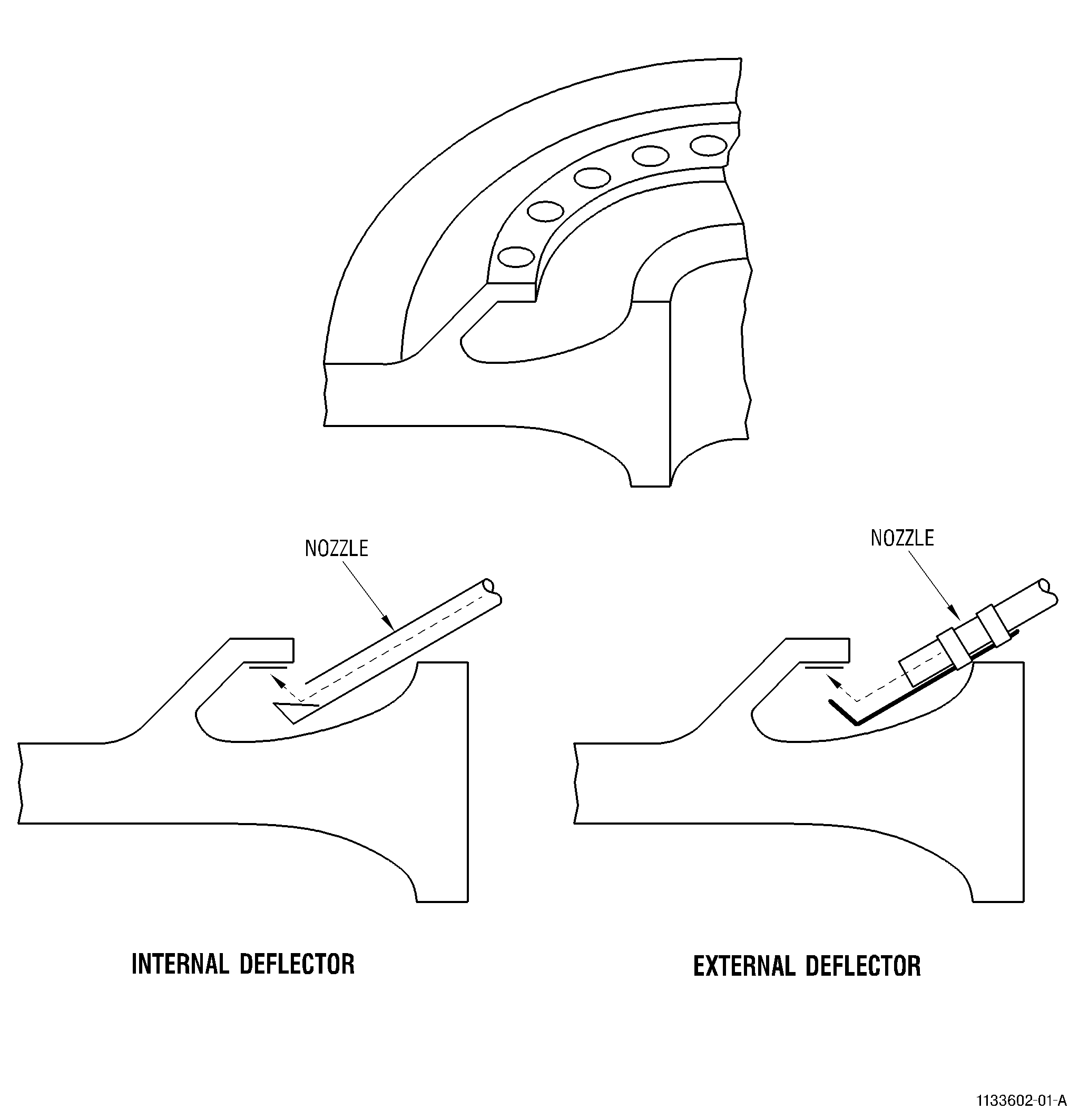
| B. | The peening media is propelled against a surface by air pressure. The shot stream can be applied by direct impingement or Ricochet peening. Direct impingement is the line of sight shot stream with standard nozzle, deflector nozzle, or lance at minimum stream to part surface angle of 35 degrees. Ricochet peening is non-line of sight peening of a part surface achieved by shot deflecting from another part surface. |
| C. | Peening is typically performed with dry medias. However, wet glass bead peening is an acceptable alternative to dry glass bead peening. The different medias are used to impart intensities in different ranges. Metallic shot is typically used to impart intensities in the Almen A range. Ceramic and glass bead medias are generally used to peen components with intensities specified in the Almen N range. |
| NOTE: |
|
| D. | Ceramic shot is a substitute for glass beads in peening operations in the Almen N range. It should be understood that, due to mass and size differences, the ceramic media will peen differently at the parameters used for glass bead media. When utilizing ceramic media, new machine parameters will need to be developed. It has been demonstrated that the ceramic media will impart a deeper stress layer at a given Almen intensity than that of a glass bead process. As a result, peening processes which are performed on parts containing thin section geometries (such as airfoil leading edges) should have intensities targeted at the lower half of the allowable intensity range. |
| E. | Peening is normally accomplished by computer-controlled, automatic, or manual machines and processes. Refer to Subtask 70-47-01-380-161, Equipment. |
| F. | For the use of alternate shot media, refer to Table 2, Table 3, and Subtask 70-47-01-380-162, Materials. |
| G. | Mixing of different types, hardnesses, or sizes of peening media is not permitted. |
| 2 . | Equipment. |
| Subtask 70-47-01-380-161 |
| A. | The peening machine incorporates movable nozzles to direct the stream of media, a rotating or traversing table to move the work through the media stream, a feed and propulsion mechanism for the media, a separator for removing shattered or defective media from circulation, and a timing device to control the duration of exposure. Special tooling such as a lance and media deflector should be provided for shotpeening the inside of bores, slots, or hollow parts, and a nozzle extension should be available for use in reaching certain difficult areas. |
| (1) | General Peening Equipment. It is expected that all peening equipment will meet the following basic requirements. |
| (a) | The shotpeening machine shall be equipped to propel shot by air pressure. Wheel peening is not permitted. |
| (b) | If the machine moves the part through the shot stream in either translation or rotation (or both) the part or nozzle (or both) shall be moved at a controlled and repeatable rate. |
| WARNING: |
|
| WARNING: |
|
| (c) | The machine should be equipped with a means for containing and controlling the dust generated during the process. The dust can contain peening media and material from the part, fixtures, and any other material that comes into contact with the air or peening media. Take precautions to protect personnel from all the materials that could be in the dust. |
| (d) | Avoid the use of part holding fixtures that could scratch the workpiece (either directly or because of residual shot on the fixture's surface). Part holding fixtures of wood or equally degradable materials or metal-to-metal contact are not permitted except for grounding area. Fixtures made of high density polymers are satisfactory. Fixtures having part locators made of hard rubber or polyurethane are satisfactory. Elastic materials like hard rubber may be preferable for repeated use to prevent shot from embedding in the fixture and creating a risk of scratching parts. |
| WARNING: |
|
| (e) | Shotpeening can generate enough static electricity to injure the operator and damage the part. Grounding by conductive features in the fixture or by a manually applied grounding probe is recommended, as follows: |
| 1 | The material used for grounding features should be soft metal and have a smooth profile where it touches the part. |
| 2 | The grounding features and probes must not contain silver, brass, bronze, copper, zinc, or lead in the area that touches the part. |
| 3 | Static electricity can also build up in the peening nozzle and peening media container. Grounding these parts to dissipate the charge is also recommended. |
| CAUTION: |
|
| (f) | If you see large electrical arcs during or after peening, make a visual inspection as follows: |
| 1 | Check the area where the grounding probe touches the part for signs of melting or pitting. |
| 2 | Repair any melting or pitting by blending per TASK 70-42-00-350-002, Blending Procedures. |
| CAUTION: |
|
| 3 | Swab etch the blended area per TASK 70-24-01-110-034, Swab Etching Procedure. |
| 4 | Spot-FPI the etched area per TASK 70-32-03-230-002, Spot Fluorescent Penetrant Inspection. |
| 5 | Peen again per the Engine/Shop Manual. |
| (g) | Wear of the blast nozzle and air jet (if applicable) can have an effect on the process quality. Peening sources must have a nozzle control plan. It is recommended that the following items are considered for a control plan: |
| 1 | Do a visual inspection of the nozzles and air jets (if applicable) before use. |
| 2 | Make sure that the nozzle and the air jet is free of visible evidence of damage or non-uniform wear when viewed at 1X (unaided eye). |
| 3 | Limit nozzle wear by 15 percent of nominal diameter and air jet wear by 10 percent of nominal diameter. |
| 4 | If wear or damage is seen, test process intensity by re-running an existing saturation curve to be sure that the nozzle still gives the required intensity. |
| (h) | Worn or damaged nozzles can affect the aim of the shot peen spray pattern. Proper verification of peening coverage is required. |
| (2) | Manual Peening Equipment. Manual peening (holding the shot nozzle in the operator's hand and moving the nozzle) is not recommended because of poor repeatability. |
| (a) | Manual nozzle peening equipment shall provide means for controlling air pressure, for allowing the operator to safely see the workpiece and the surfaces being peened, and for providing a steady flow of peening media to the nozzle. |
| (b) | Manual peening is not generally permitted on rotating, life-limited hardware, or on high pressure turbine (HPT) blades, but may be specified for local repairs and is permitted only under the following circumstances: |
| 1 | On components such as tube assemblies whose configurations may lend themselves to more uniform coverage by hand manipulation of a nozzle rather than with machine oscillated nozzles. |
| 2 | In small areas of large static parts after local metal removal or weld areas by hand nozzle or flapper peening per TASK 70-47-04-380-019, Rotary Flap Peening. |
| 3 | Onrotating, life-limited parts, or on HPT blades only when specifically approved by the process document and only in authorized locations on the parts. |
| (3) | Automatic Peening Equipment. Automatic equipment may require manual setup and configuration of the part, nozzle positions, and process parameters. In addition, the monitoring of the process parameters may require operator supervision. However, during operation, the machine should not require operator intervention to complete the operation. |
| (a) | The machine shall be equipped with a process timer or a cycle counter to assure repeatable peening time for the parts. |
| (b) | In order to prevent the process from dwelling in one spot unintentionally, the machine must have a process start and stop interlock to assure that the table is rotating at all times while the blast air pressure is turned on. |
| NOTE: |
|
| (c) | The machine can include a means for automatically separating broken or undersized media from the machine during operation before re-use. Integral separation or classifying equipment is recommended. |
| (d) | It is the peening source responsibility to assure satisfactory aim of the peening stream toward the part to achieve the required intensity and coverage. |
| CAUTION: |
|
| (e) | Runout, nozzle setup variation, position and angular repeatability must be controlled to prevent incorrect aiming of the spray pattern. Severely worn table bearings that permit the part position to vary can cause a lack of uniform coverage. Control is especially important where the moving parts are near the part surfaces (such as when a lance is used inside small bolt holes). In these cases, much tighter control is necessary to prevent damage than is necessary to get good coverage. |
| (4) | Computer Controlled Peening Equipment. Computer controlled peening equipment utilizes a computer (or PLC or NC-type controller) for storing, setting, and controlling process parameters. The machine shall have the capability to select, control, and monitor: |
| The peening air pressure |
| The shot flow rate |
| The peen time, feedrates, or cycles |
| The part and nozzle position, orientation, and speed |
| The lance rotation speed, if applicable. |
| (a) | The machine must be equipped with a process timer or cycle counter to assure repeatable peening time for the parts. |
| (b) | In order to prevent the process from dwelling in one spot unintentionally, the machine must have a process start and stop interlock to assure that the table is rotating at all times while the blast air pressure is turned on. |
| NOTE: |
|
| (c) | The peening machine must continuously monitor and shut down when it detects variations in any of the following parameters that would result in a process shift in intensity and coverage outside the repair requirements: |
| Air pressure |
| Shot flow rate |
| Part/nozzle position and speeds. |
| (d) | The machine must include a means for automatically separating broken, oversized, or undersized media from the machine during operation before re-use. 100 percent of the media must pass through the separator system before re-use. Separator systems usually have vibrating screens that discard oversized and undersized particles. Spiral separators can be used to further improve the removal of non-round particles, but it is not necessary for 100 percent of the media to pass through spiral separators before re-use. |
| (e) | It is the peening source responsibility to assure satisfactory aim of the peening stream toward the part to achieve the required intensity and coverage. |
| CAUTION: |
|
| (f) | Runout, nozzle setup variation, position and angular repeatability must be controlled to prevent incorrect aiming of the spray pattern. Severely worn table bearings that permit the part position to vary can cause a lack of uniform coverage. Control is especially important where the moving parts are near the part surfaces (such as when a lance is used inside small bolt holes). In these cases, much tighter control is necessary to prevent damage than is necessary to get good coverage. |
| B. | Almen Fixtures. Almen fixtures reproducing the configuration of the work piece for evaluation of ricochet peening shall be designed and maintained to have the same contours and shading effects as the work piece within 0.060 inch (1.5 mm). The material used to represent the ricochet surfaces shall have similar hardness to the part they represent so that the behavior of the shot bouncing off the surface is similar to the actual part. |
| 3 . | Materials. |
| Subtask 70-47-01-380-162 |
| A. | Shot and beads are essentially spherical, and are capable of producing the required peening action without excessive fracturing of particles. Various shot and bead sizes are available to permit the selection of different peening intensities stipulated in the Engine/Shop Manual. Air-driven systems with multiple nozzles are preferred. |
| NOTE: |
|
| (1) | Cast Steel Shot. |
| (a) | Cast Steel Shot, High Hardness C04-271 shall be purchased to the requirements in AMS 2431/2, Peening Media (ASH) Cast Steel Shot, High Hardness (55-62 HRc). See Table 1 of this document for reference on shot size definitions. |
|
|||||||||||||||||||||||||||||||||||||||||||||||||||||||||||||||||||||||||||||||||||||||||||||||||||||||||||||||||||||||||||||||||||||||||||||||||||||||||||||||||||||||||||||||||||||||||||||||||||||||||||||||||||||||||||||||||||||||||||||||||||||||||||||||||||||||||||||||||||||||||||||||||||||||||||
| (b) | Cast steel shot, Regular Hardness C04-286 must be purchased to the requirements in AMS 2431/1, Peening Media (ASR) Cast Steel Shot, Regular Hardness (45-52 HRc). Refer to Table 1 of this document for reference on shot size definitions. |
| (2) | Conditioned Carbon Steel Cut Wire Shot. |
| (a) | Cut wire shot material must conform to the requirements of SAE specifications AMS 2431/8 (55-62 HRc) or GE specification D50TF11 CL-B (50-62 HRc). |
| NOTE: |
|
| (b) | Refer to Table 2 to determine the equivalent conditioned cut wire size to various cast steel shot. |
| (c) | Wire diameters and size distributions are listed in Table 2. |
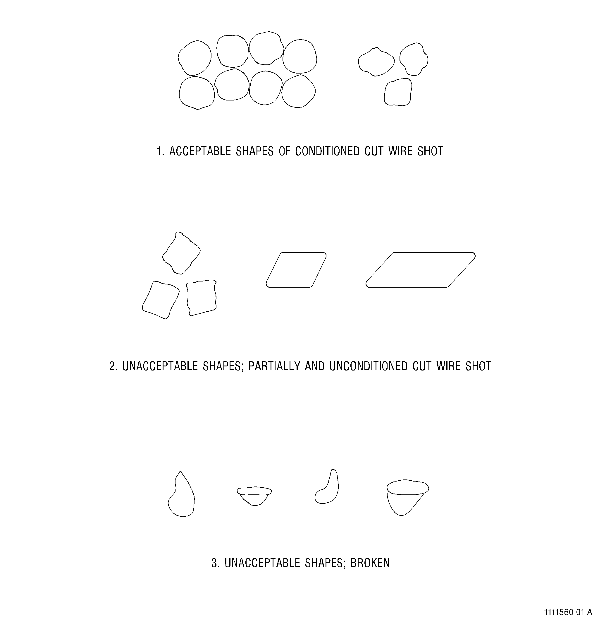
| (d) | Cut wire must be conditioned prior to purchase so that the number of unconditioned or partially conditioned particles do not exceed the requirements of Table 2 and Figure 2. |
| (e) | Cut wire sources are listed in TASK 70-80-04-800-801, Consumable Products - Cleaning Compounds and Solvents, CCW14 C04-166, CCW17 C04-298, CCW20 C04-167, CCW31 C04-178, and CCW39 C04-297. |
|
||||||||||||||||||||||||||||||||||||||||||||||||||||||||||||||||||||||||||||||||||||||||||||||||||||||||||||||||||||||||||||||||||||||||||||||||||||||||||||||||||||||||||||||||||||||||||||||||||||||||||||||||||||||||||||||||||||||||||||||||||||||||||||||||||||||||||||||||||||||||||||||||||||||||||||||||||||||||||||||||||||||||||||||||||||||||||||||||||||||||||||||||||||||||||||||||||||||||||||||||||||||||||||||||||||||||||||||||||||||||||||||||||||
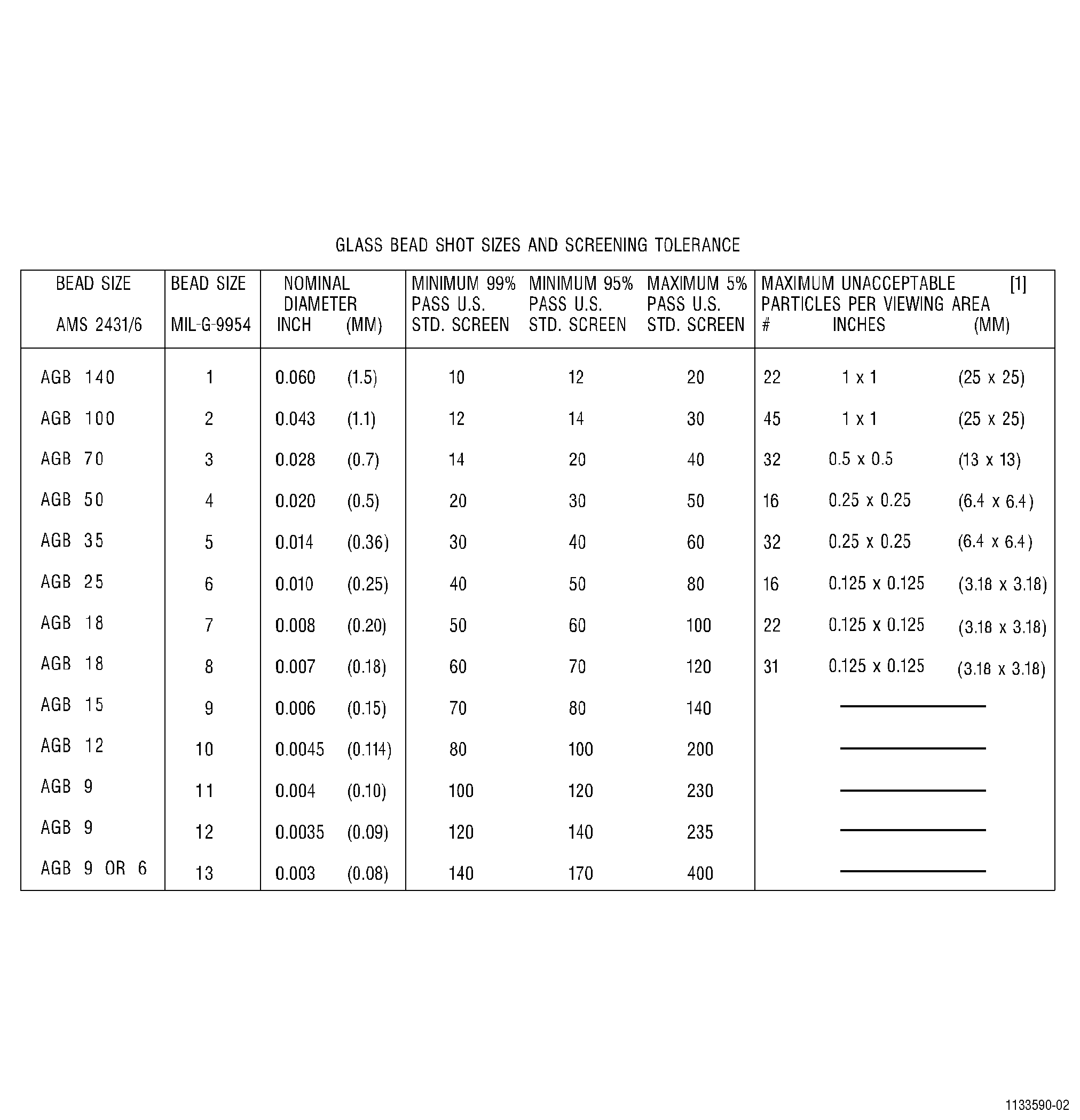
| (3) | Glass Beads. |
| (a) | Glass beads used for peening shall conform to the requirements of AMS 2431/6. Refer to Figure 1 for glass bead size definitions. |
| NOTE: |
|
| (b) | The suppliers of glass beads are in , Consumable Products - Cleaning Compounds and Solvents, C04-272 . |
| (4) | Ceramic Beads. |
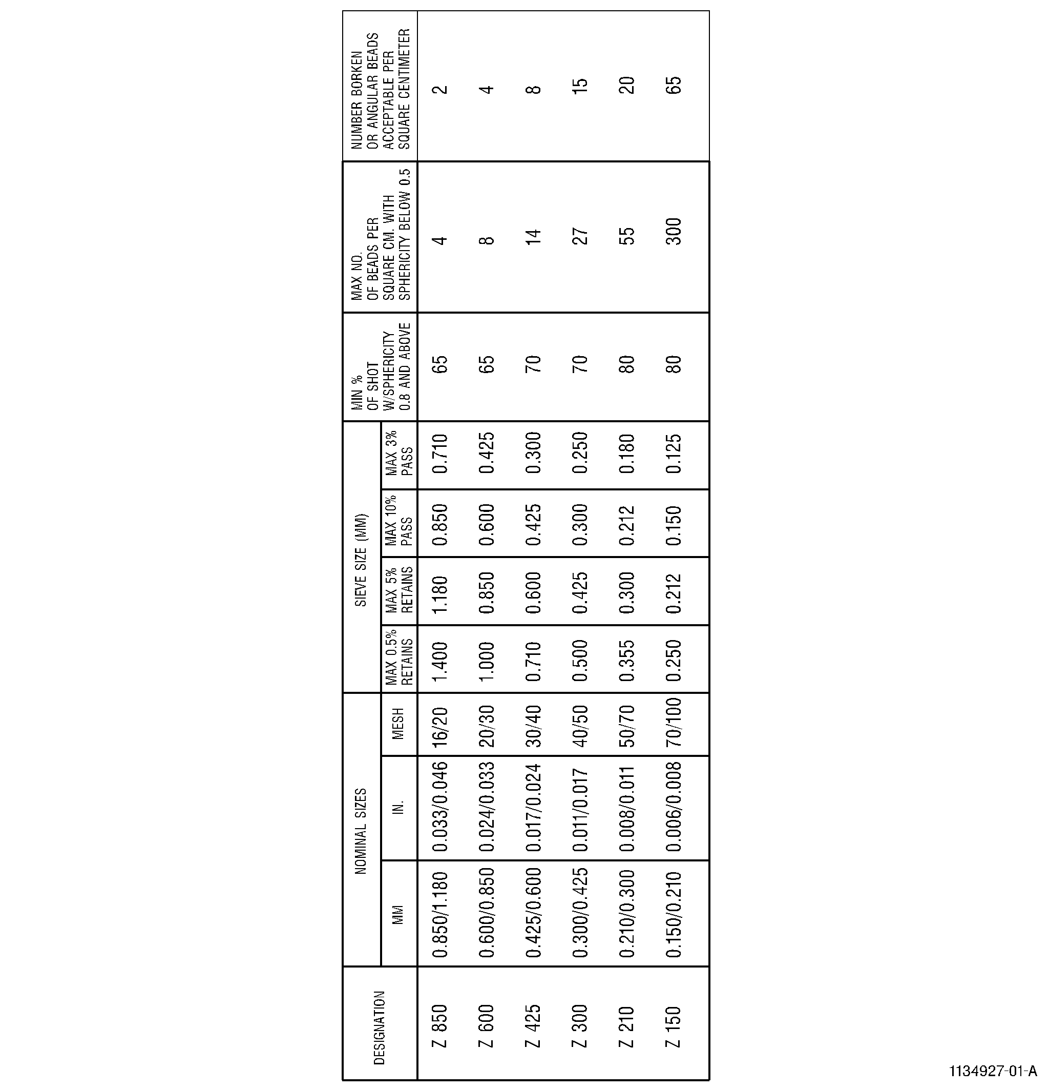
| (a) | Ceramic beads used shall conform to requirements of AMS 2431/7. |
| (b) | Bead size shall conform to requirements in Figure 4. |
| (c) | Recommended beads are C04-161 , C04-162 , or (C04-179). |
| (5) | Material Process Quality Checks. |
| NOTE: |
|
| NOTE: |
|
| (a) | Cast Steel Shot. |
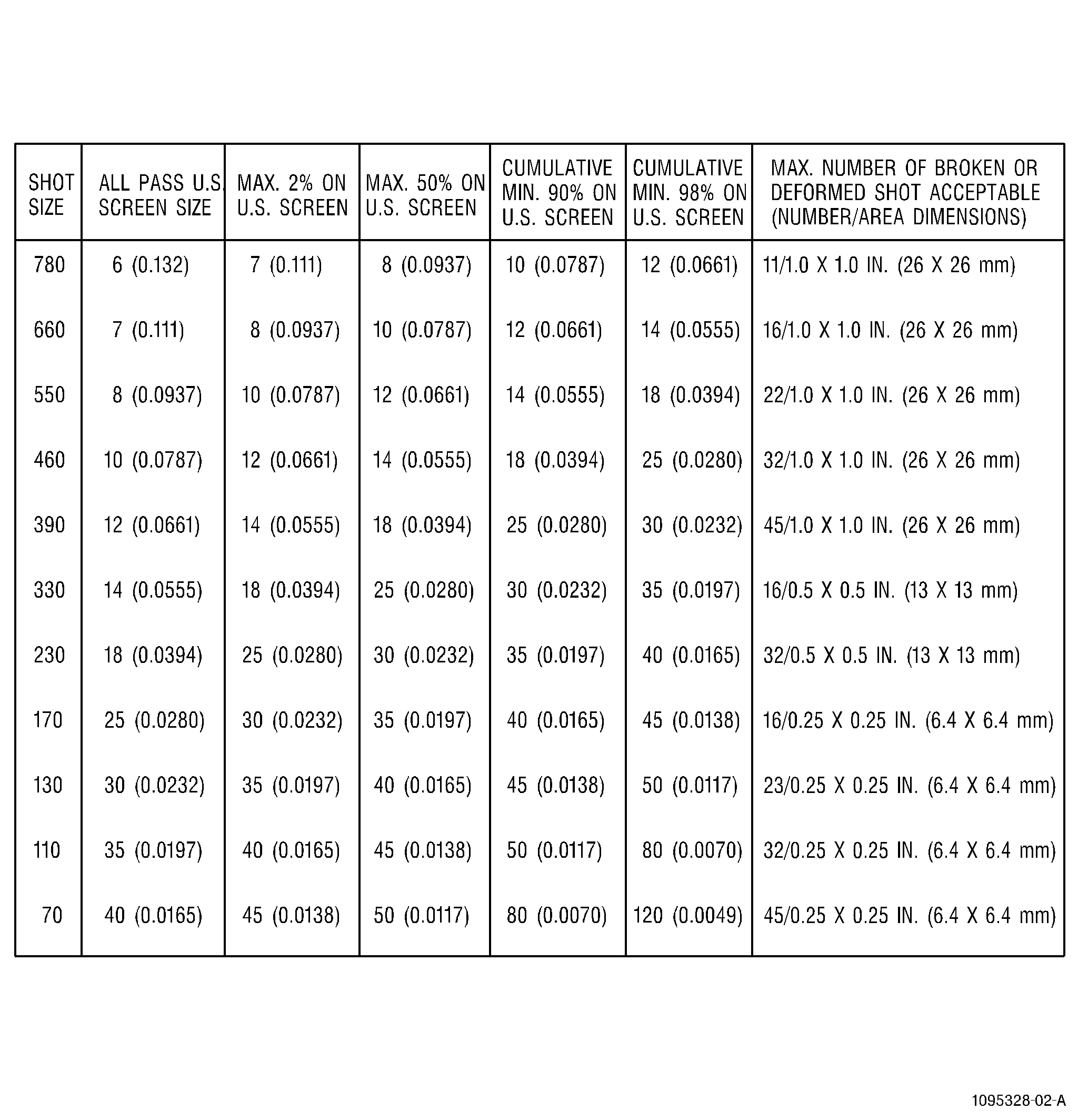
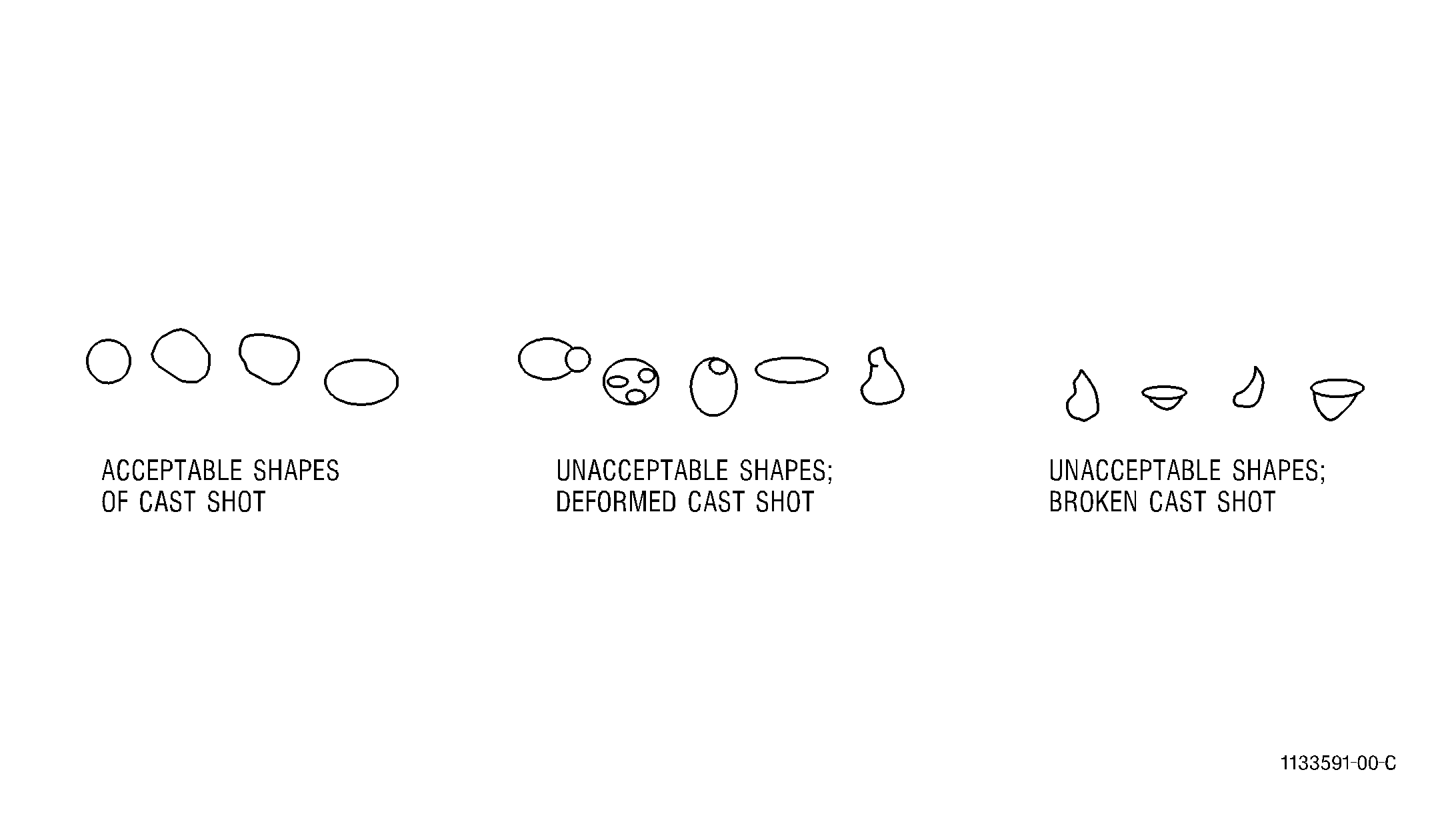
| 1 | Cast steel shot should be visually examined at least once during every eight-hour shift for deformed or broken shot. If the peen machine is equipped with an integral timer that measures accumulated peening time, the interval shall be once every eight hours of peening time. If a part peening cycle will exceed the eight-hour interval based on cycle time, the media inspection shall be performed prior to executing the peening cycle. The records of inspection and machine hour reading shall be maintained to substantiate the extended run time between inspections. Typical test is to collect a single layer of shot material on a piece of cellophane tape within the areas defined in Table 1. Using a 10X or 20X magnifier, count the number of deformed (sharp cornered, teardrop, hollow, or elongated greater than a two to one length to width ratio) or broken shot pieces. For example, no more than 32 deformed or broken pieces for S110 and no more than 23 pieces for S130 shot. Refer to Table 1 (quantity/area) and Figure 14 (shapes). |
| 2 | Uniformity of cast shot in machine shall meet the uniformity requirements listed in Table 4. Shot not meeting this criteria shall be discarded or reclassified. |
| (b) | Glass Beads. |
| 1 | Broken bead content shall not be greater than permitted by Figure 1. Broken bead content shall be determined by separation and weighing, or by visual inspection. It is recommended that dry bead peening operations be checked every two hours. The entire bead charge should be replaced when the broken bead content exceeds limits in Figure 1. |
| 2 | Wet glass bead peening operations should operate with a slurry consisting of 35 to 45 percent glass bead, the remainder water. Glass content should be measured at 15 to 30 minute intervals using a visual test on a graduated cylinder. The entire slurry charge should be replaced every 2 hours. For computer controlled peening equipment with integral media separators or other forms of continuous media filtration, operating times or concentrations outside of the previously stated ranges may be used when statistically substantiated by media quality and intensity data which shall be maintained by the source. |
|
|||||||||||||||||||||||||||||||||||||||||||||||||||||||||||||||||||||||||||||||||||||||||||||||||||||||||||||||||||||||||||||||||||||||||||||||||
| (c) | Ceramic Beads. |
| 1 | Broken bead content shall not be greater than permitted by Figure 4. Broken bead content shall be determined by separation and weighing or by visual inspection. It is recommended that ceramic bead peening operations be checked every four hours. The entire bead charge should be replaced when the broken bead content exceeds limits in Figure 4. |
| (d) | Cut Wire Shot. |
| 1 | Cut wire should be visually examined at least once during every eight-hour shift for deformed or broken shot (refer to Figure 2). If the peen machine is equipped with an integral timer that measures accumulated peening time, the interval shall be once every eight hours of peening time. If a part peening cycle will exceed the eight-hour interval based on cycle time, the media inspection shall be performed prior to executing the peening cycle. The records of inspection and machine hour reading shall be maintained to substantiate the extended run time between inspections. The number of allowable unacceptable pieces per sample is defined in Table 2. |
| 2 | Recommended magnification for media inspection is 10-20X. |
| 4 . | Procedure. |
| Subtask 70-47-01-380-163 |
| A. | Equipment Check. |
| Check the peening machine and its connected services for proper operation as follows: |
| (1) | Ascertain that machine is loaded with proper size, type, and quality of media. |
| WARNING: |
|
| (2) | Be sure that air supply (volume) is sufficient for operation, and that pressure can be maintained at the required pressure for the established process. |
| (3) | See that media flows freely (for gravity-suction machines) from all nozzles for a few seconds after a short run, and that air pressure shuts off before opening door (this assures that the safety interlock is working properly). |
| (4) | Check rotating table is operating at the required RPM. |
| (5) | Make sure that process timing control is functioning accurately. |
| (6) | Determine that nozzles are not excessively worn. |
| B. | Preparation of Part for Peening. |
| (1) | Part to be shotpeened must be repaired, heat treated, machined, ground, polished, and burrs and sharp corners removed as necessary before shotpeening. Part must be within dimensional and surface finish limits unless otherwise specified. |
| (2) | When required, magnetic-particle or fluorescent-penetrant inspection must be completed before shotpeening. |
| (3) | Part must be clean and free from all dirt, grease, and oil. |
| (4) | Mask designated areas that are not to be shotpeened using masking fixture if available, or masking tapes that are capable of protecting the part from the shot stream, like one of those in C10-021 plastic tape. Plastic caps, rubber plugs, or plastic screws can be used to plug holes. Make sure that edges of tape are in firm contact with the part. The tolerance of the masking position shall be 0.250 inch (6.35 mm) maximum, unless otherwise specified. When tape masking is used, the type and number of layers must be sufficient to prevent peening under the masking. |
| (5) | Record part number, serial number, location of each, and method of application so that part can be remarked after peening. |
| C. | Machine Setup. |
| (1) | Ensure that machine contains proper media size as stipulated in instructions for specific part. |
| (2) | Place part and holding fixture in machine, and adjust nozzles per process document to peen the required area. |
| CAUTION: |
|
| (3) | Set machine traverse limits as required, to provide necessary distance and location of stroke with respect to the part. |
| (4) | Leaving nozzles in position, remove part, and replace with proper Almen strip fixture. Check nozzle position to be sure of proper alignment with Almen strips. |
| D. | Peening Time Determination. The peening time shall be the longer of the time required for full surface coverage (see Step 4.F.) and the time required for Almen strip saturation. Peening operations requiring fixture with multiple Almen strips shall meet saturation and coverage requirements at all strip locations. The peening time is governed by the longest time required to reach coverage or saturation on any of the strips on the fixture. |
| E. | Intensity Determination. Refer to Figure 13. |
| NOTE: |
|
| NOTE: |
|
| NOTE: |
|
| (1) | The saturation point shall be determined as follows: |
| (a) | The saturation point is determined from a saturation curve. Refer to Figure 13. It is the minimum duration of peening which, when doubled, increases the Almen strip arc height by not greater than 10 percent except that 15 percent maximum may be used in the following situations: |
| 1 | For gravity accelerated peening of titanium fan blades. |
| 2 | For glass bead peening of fan and compressor airfoils. |
| 3 | For steel shotpeening with intensity equal to or less than 15N (5A equivalent), provided that the saturation curves substantiating the process are drawn as smooth curves through mean values, calculated from 10 arc height measurements for each point. Confirmation of the saturation point may be aided by an A strip curve run under identical conditions to the N curve, with 5 measurements per point. |
| (b) | Almen test strips, as shown in Figure 12, shall be flat within ± 0.0005 in. (0.013 mm) for A Almen strips, and ± 0.0007 in. (0.018 mm) for N Almen strips. If a system of compensating for initial out-of-flatness is used, strips out-of-flatness up to ± 0.001 in. (0.03 mm) may be used. Mechanically deforming strips to meet the flatness requirement is not permitted. |
| NOTE: |
|
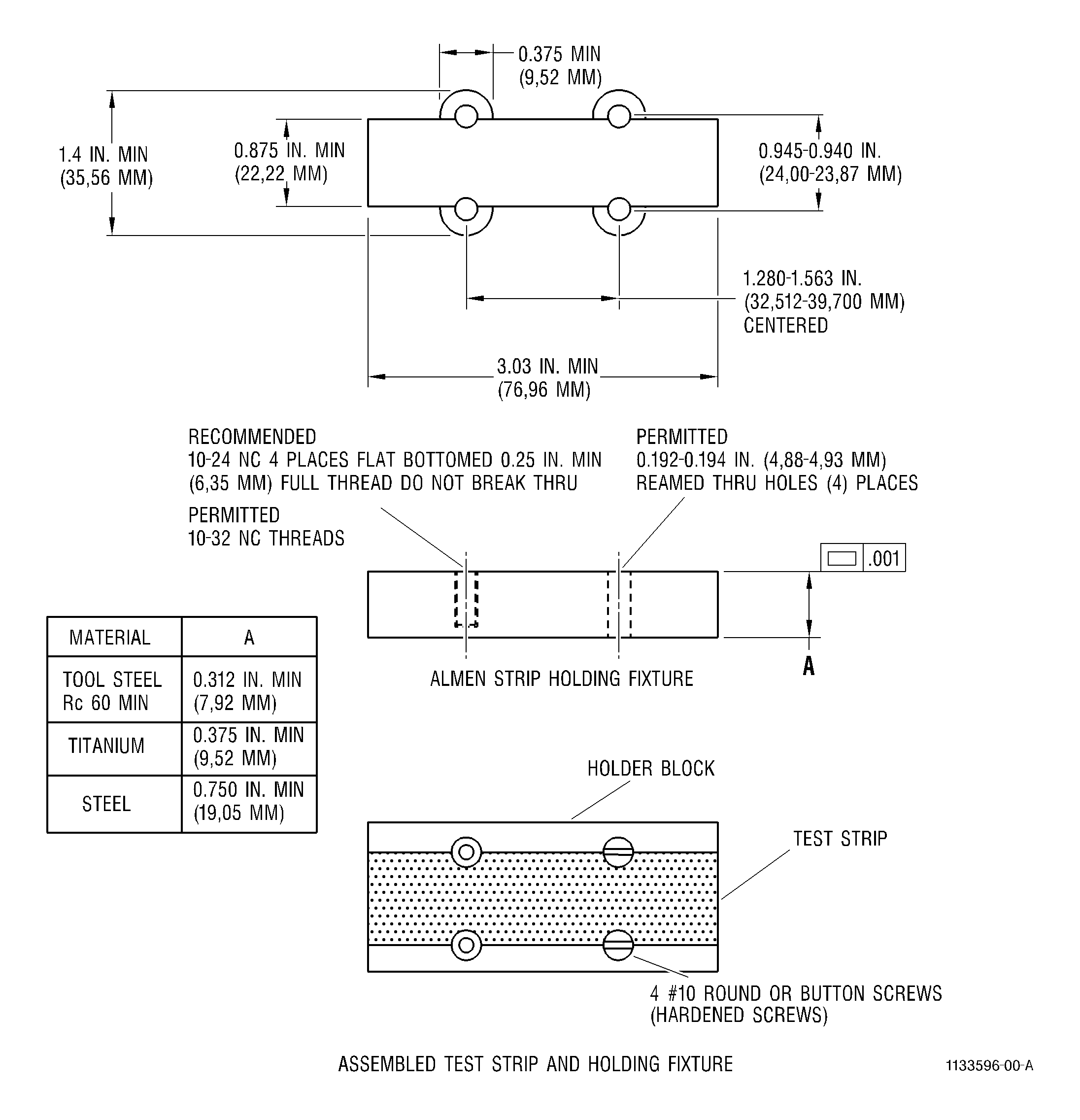
| (c) | Almen test strips shall be mounted on holders or on fixtures incorporating such holders conforming to the requirements of Figure 11. |
| (d) | The type of fixture (simple, simulative, or scrap part) used to support the Almen strips shall be as specified in the repair. Almen support blocks shall be bolted securely or welded to the fixtures. |
| NOTE: |
|
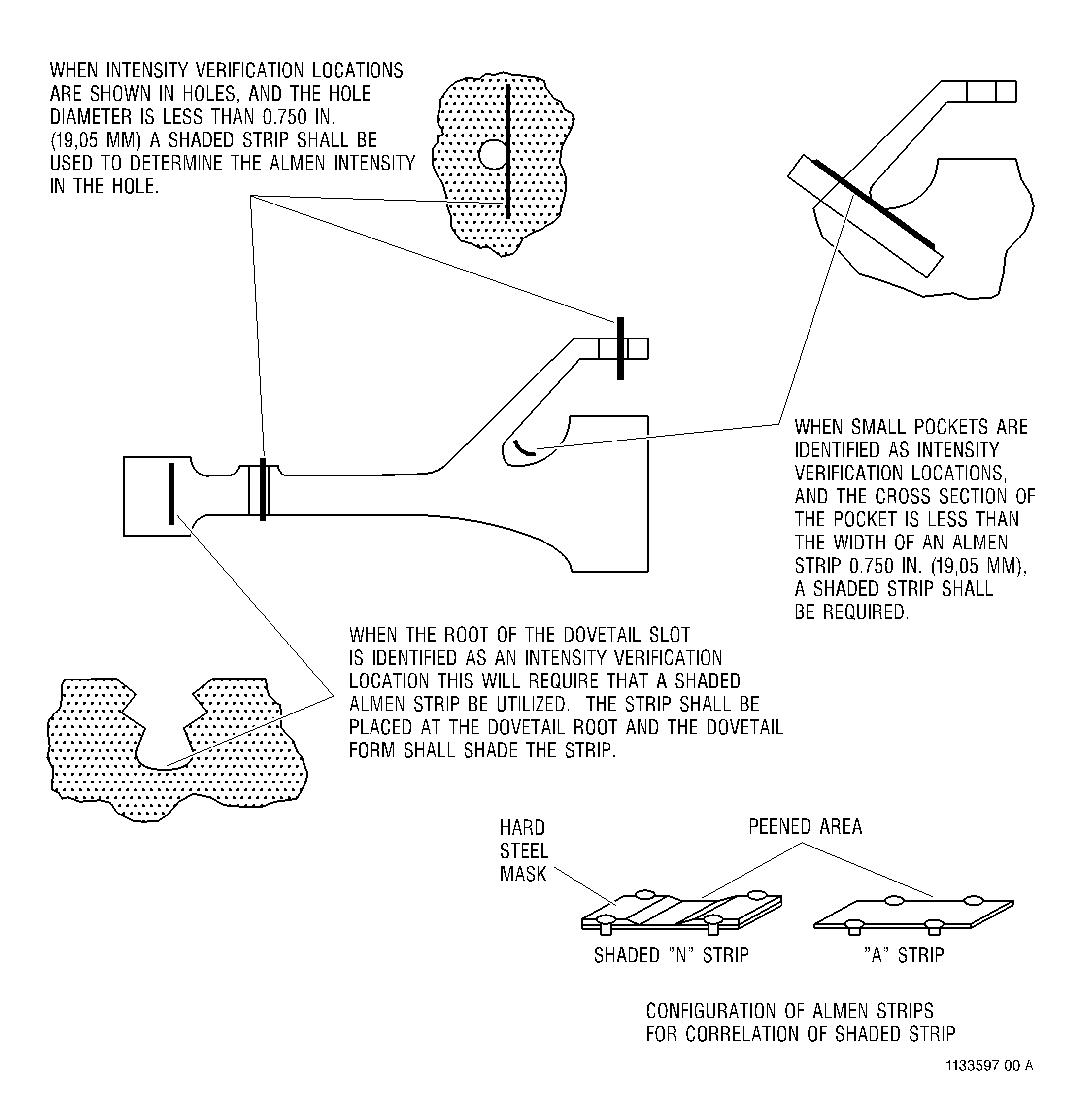
| (e) | Shaded strips shall be used for situations shown in Figure 10. In these cases, partially masked N strips shall be used. Calibration to the required part intensity shall be carried out using the N strip, masked with 0.090 in. (2.29 mm) minimum thickness metal to expose the same area as the Almen fixture, and peening on a flat plate along with a full standard strip. |
| NOTE: |
|
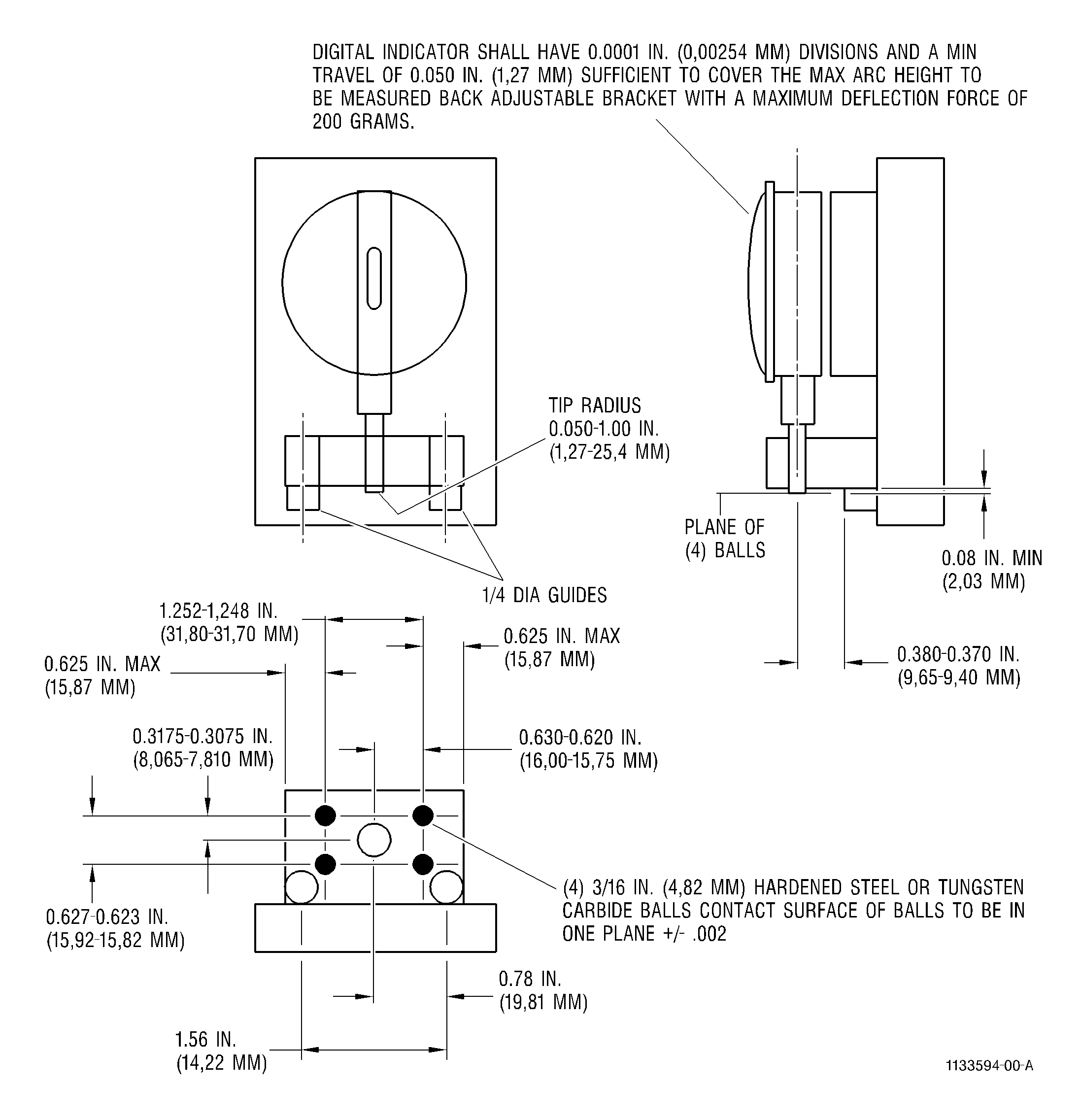
| (f) | After peening, the arc height of each Almen strip shall be measured in an Almen gauge conforming to the dimensional relationship of the four contact balls, and the indicator anvil and ball hardness of Figure 9. A peened Almen strip shall not be re-peened after it has been removed from a holder. |
| (g) | During initial process development, a separate saturation curve, such as that shown in Figure 13, shall be made for each location on the part where verification is required. There shall be at least four Almen strips peened for different lengths of time to determine each curve. The number of Almen strips shall be sufficient to clearly establish the shape of the saturation curve, and to determine the saturation time. One point shall be in the area of the knee of the curve. |
| (h) | If an Almen strip location is peened in more than one operation, intensity shall be determined at the saturation point for each operation. If two operations peening one location are exact mirror images resulting from inverting the part, the saturation point may be generated by combining the two operation if saturation is not achieved in each separately. |
| F. | Coverage Determination. |
| (1) | Full coverage is required on all surfaces where peening is specified. Coverage shall be verified for all surfaces requiring peening as follows: |
| (a) | Visual inspection of accessible surfaces shall show a continuous pattern of overlapping dimples at 10X minimum magnification. Inaccessible surfaces may be inspected using illuminated borescope or angled, lighted mirrors. |
| (b) | As an alternate, fluorescent tracer inspection of surfaces shall be accomplished by reviewing a previously coated, then peened surface under a suitable black light. Fluorescent tracer material must conform to the requirements of Fluorescent Tracer Material, Shot Peen C05-121 . Complete coverage is achieved when no fluorescence occurs under black light. A minimum acceptable condition shows isolated flecks of fluorescent indications. |
| NOTE: |
|
| (2) | Coverage time is the time required to achieve the uniform surface pattern in Step 4.F.(1)(a). Full coverage is defined as time required for 100 percent coverage. Multiple coverages are times in access of time required to achieve 100 percent coverage. For example, 125 percent coverage is 1.25 times the time for full coverage, 200 percent coverage is 2.0 times the time for full coverage. |
| G. | Peening the Parts. |
| WARNING: |
|
| (1) | Install the part, mounted in the holding fixture, back into the machine. Check nozzle position to be sure that nozzles are still properly directed toward the area of the part to be peened. Adjust if necessary. |
| (2) | Peen the part by operating the machine in accordance with the cycle determined in Step 4.E. |
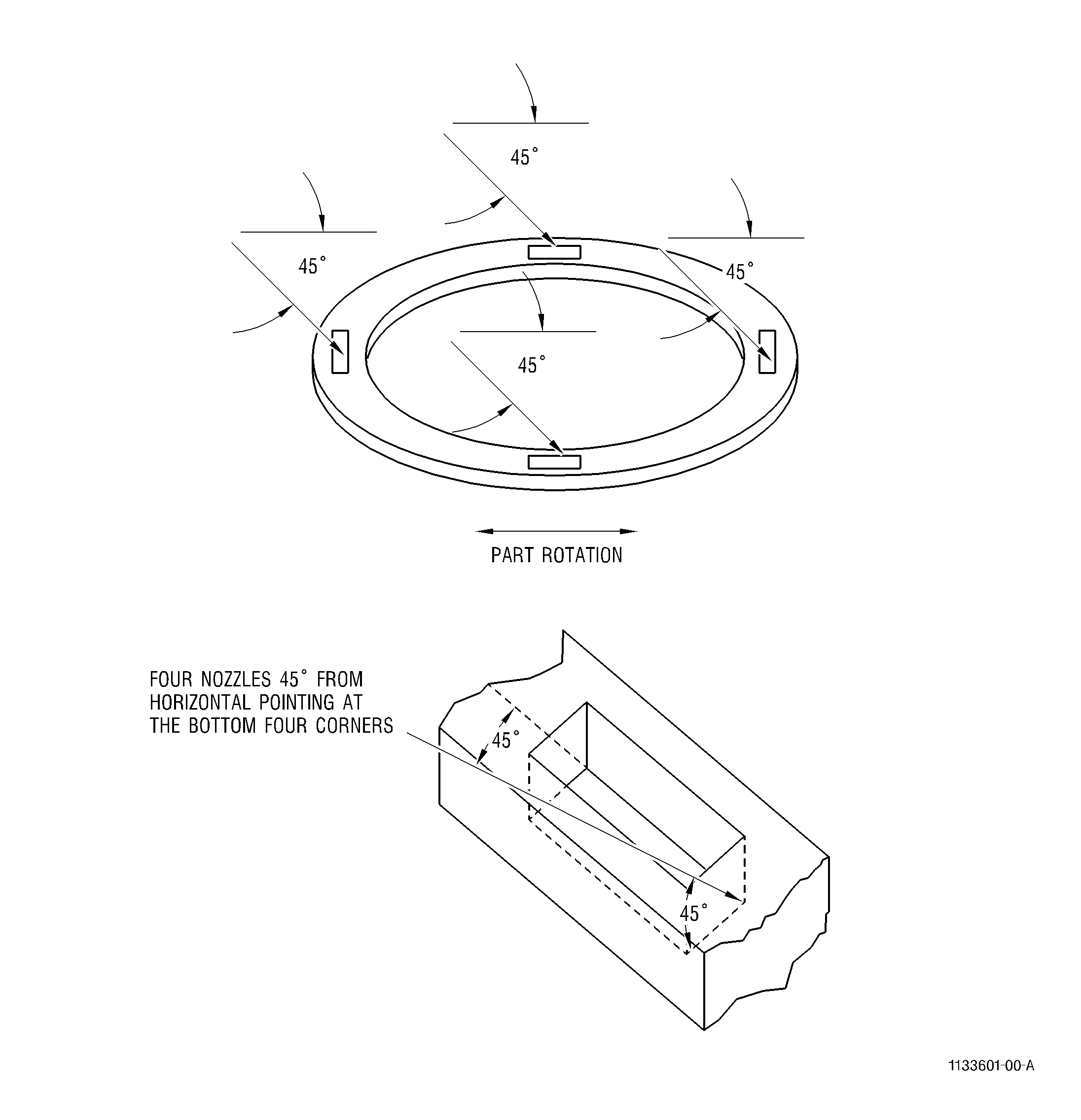
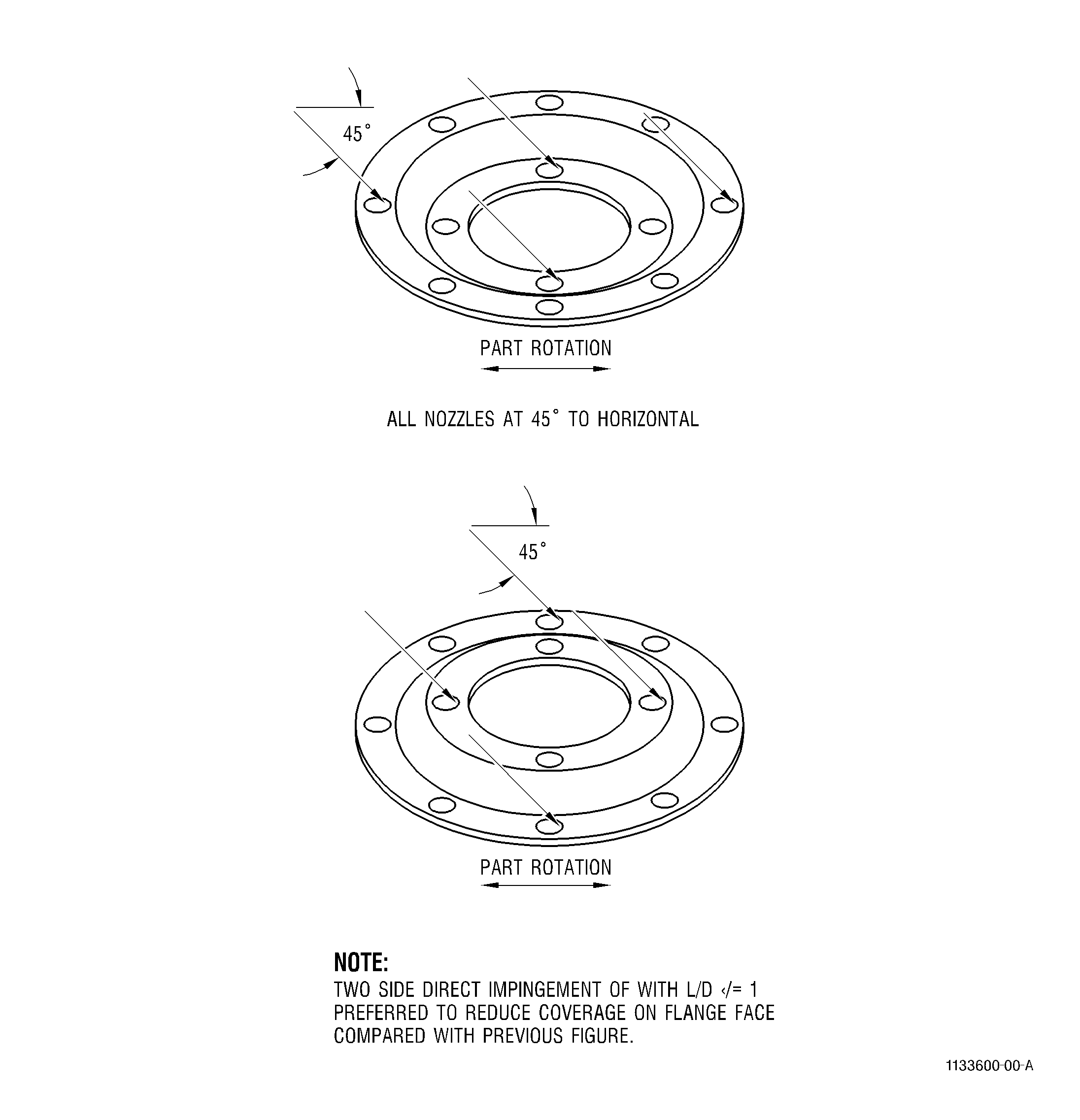
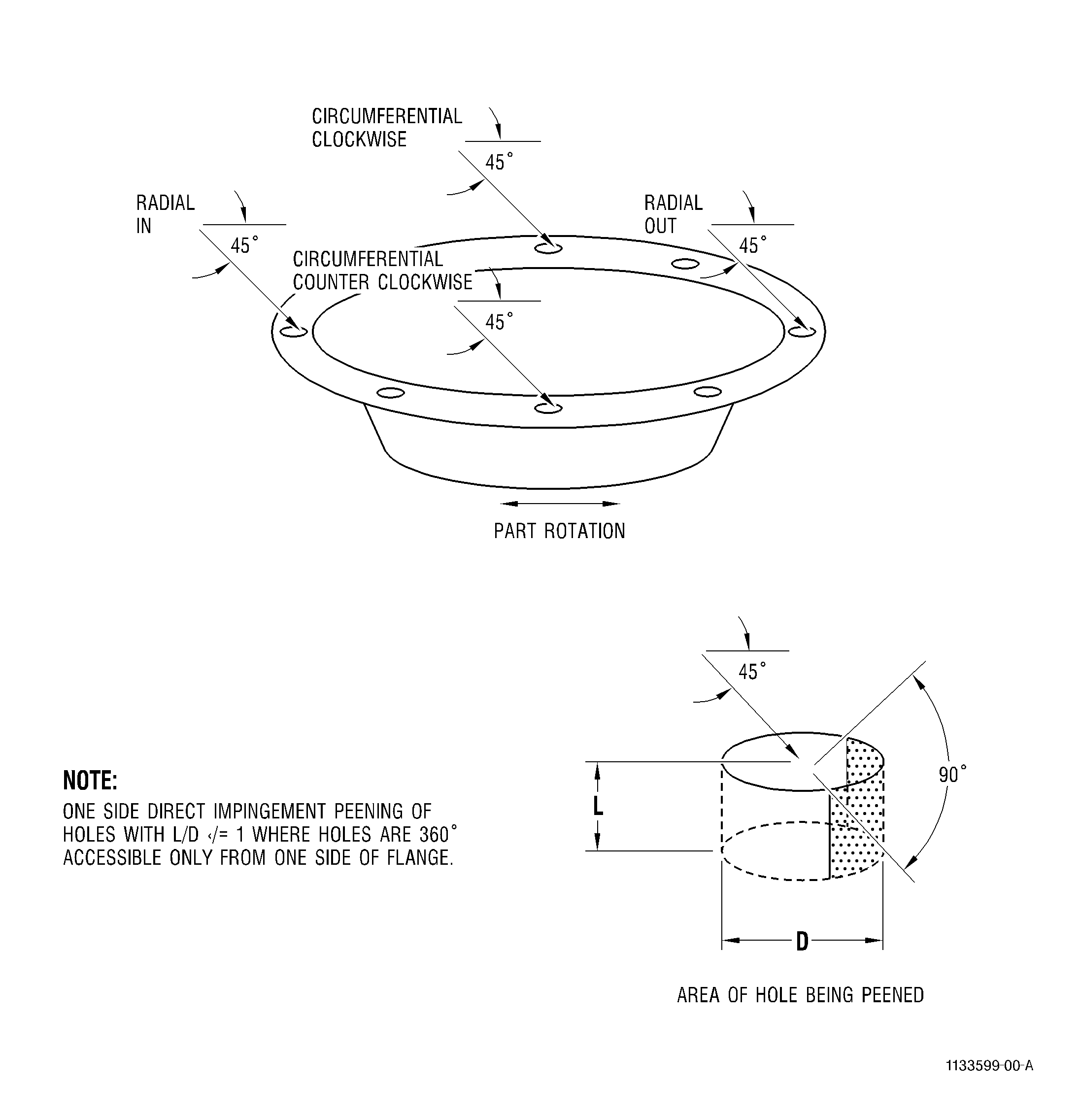
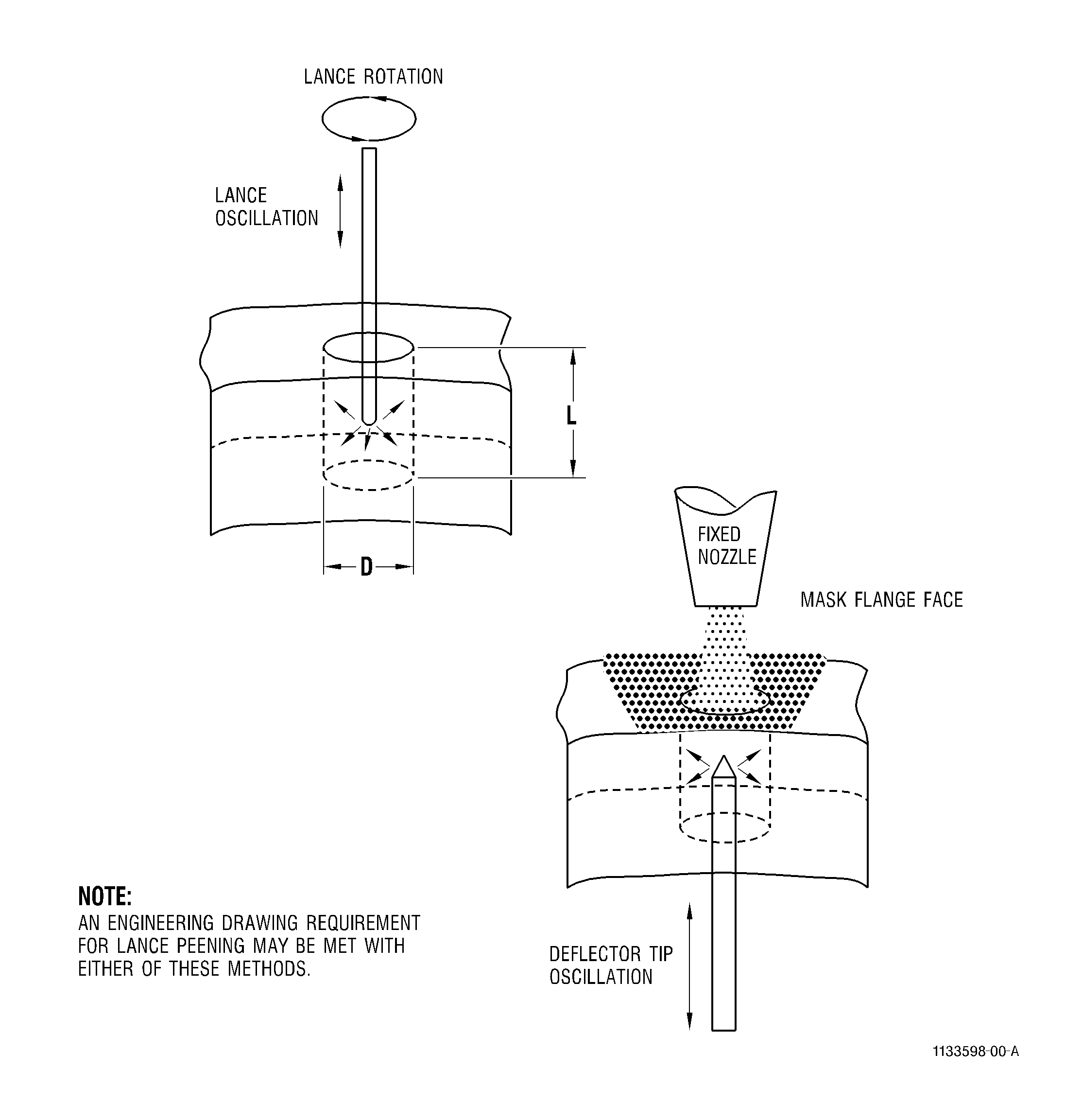
| (3) | Reference Figure 5, Figure 6, Figure 7, Figure 8, and Figure 15 for examples of recommended peening techniques for various applications. |
| H. | Quality Check. |
| NOTE: |
|
| (1) | Verify complete peening of required area(s) of the part(s) by examining under 10 power magnification. Surfaces should have a uniform peened appearance on all required areas. |
| (2) | If proper coverage has not been achieved, check equipment setup as directed in Step 4.A. and 4.C. Repeen to achieve complete coverage in required areas. Record total coverage time. |
| (3) | Perform visual inspection of all edges to assure that no burrs or rollover of edges has occurred. If burrs or rollover are detected, the part edges should be blended. Refer to TASK 70-42-00-350-002, Blending and Removal of High Metal Procedures, to remove burrs and the part should be repeened. |
| I. | Cleanup. |
| After peening, remove all masking and residue. Blow off all shot, beads, or fragments, using clean, dry shop air. Remark part number and serial number by the original method if they were obliterated by peening. Apply preservative as required. |