| COMMERCIAL ENGINE STANDARD PRACTICES MANUAL | Dated: 02/13/2024 | |
| SPM 70-47-04 ROTARY FLAP PEENING | ||
| COMMERCIAL ENGINE STANDARD PRACTICES MANUAL | Dated: 02/13/2024 | |
| SPM 70-47-04 ROTARY FLAP PEENING | ||
| TASK 70-47-04-380-019 |
| 1 . | General. |
| CAUTION: |
|
| A. | Many engine components are shot peened at time of manufacture as a method to achieve improved cyclic life. Repair of these parts often requires local blending to remove surface imperfections. Blending may partially or completely remove the compressive surface layer induced by shot peening. An acceptable method of restoring the compressive layer in noncritical areas, as an alternate to standard shop peening procedure per TASK 70-47-01-380-016, Shot Peening, is rotary flap peening. This procedure is to be used only when specifically directed by the Engine/Shop Manual. |
| B. | Unless specified differently, TASK 70-47-06-380-801, Needle Peening, can be used as alternative to TASK 70-47-04-380-019, Rotary Flap Peening. |
| 2 . | Equipment. |
| Subtask 70-47-04-380-191 |
| C. | The following equipment is required and may be obtained as shown: |
| (1) | No. 2 Almen Gage. (SAE J442 compliant with type 2 Almen Gage) |
| (2) | Timing Device (Commercial). |
| (3) | Magnetic Almen Strip Holder, 3M No. 9016, or equivalent. 3M Company. Refer to the List of Suppliers in Step 4 of 70-80-00. |
| (4) | Hand operated grinder or flexible shaft driven by an electric or compressed air motor with adjustable shaft speed control (Commercial). Equivalent alternative tools and equipment may be used. |
| NOTE: |
|
| (5) | Mandrel, Rotopeen, 3M No. 7212, or equivalent. 3M Company. Refer to the List of Suppliers in Step 4 of 70-80-00. |
| (6) | A hand-held tachometer used to determine shaft rpm. Tachometer is not necessary if the system has calibrated closed-loop speed control. |
|
| 3 . | Materials. |
| Subtask 70-47-04-380-192 |
|
| 4 . | Procedure. |
| Subtask 70-47-04-380-193 |
| D. | Preparation of Part and Flap for Rotary Flap Shot Peening. |
| (1) | Part to be peened must be repaired and blended to remove burrs and sharp corners from area to be peened. |
| (2) | Magnetic-particle inspection or fluorescent-penetrant inspection (preceded by appropriate etching) when required must be completed before shot peening. |
| (3) | Areas not to be peened, adjacent to areas being peened, shall be masked to avoid contact with rotary flap. |
| (4) | Area of part to be peened must be clean and free of all dirt, grease or oil. |
| (5) | New flaps must be examined to confirm that no resin coating exists over the shot prior to use. If a coating exists, the flap must be conditioned by operation against an abrasive paper or a hard surface to remove the coating. The resin coating, if not removed, will cushion the impacts against the test strip and will effect delivered intensity until resin has worn off. |
| Subtask 70-47-04-380-195 |
| E. | Determination of Peening Requirements. |
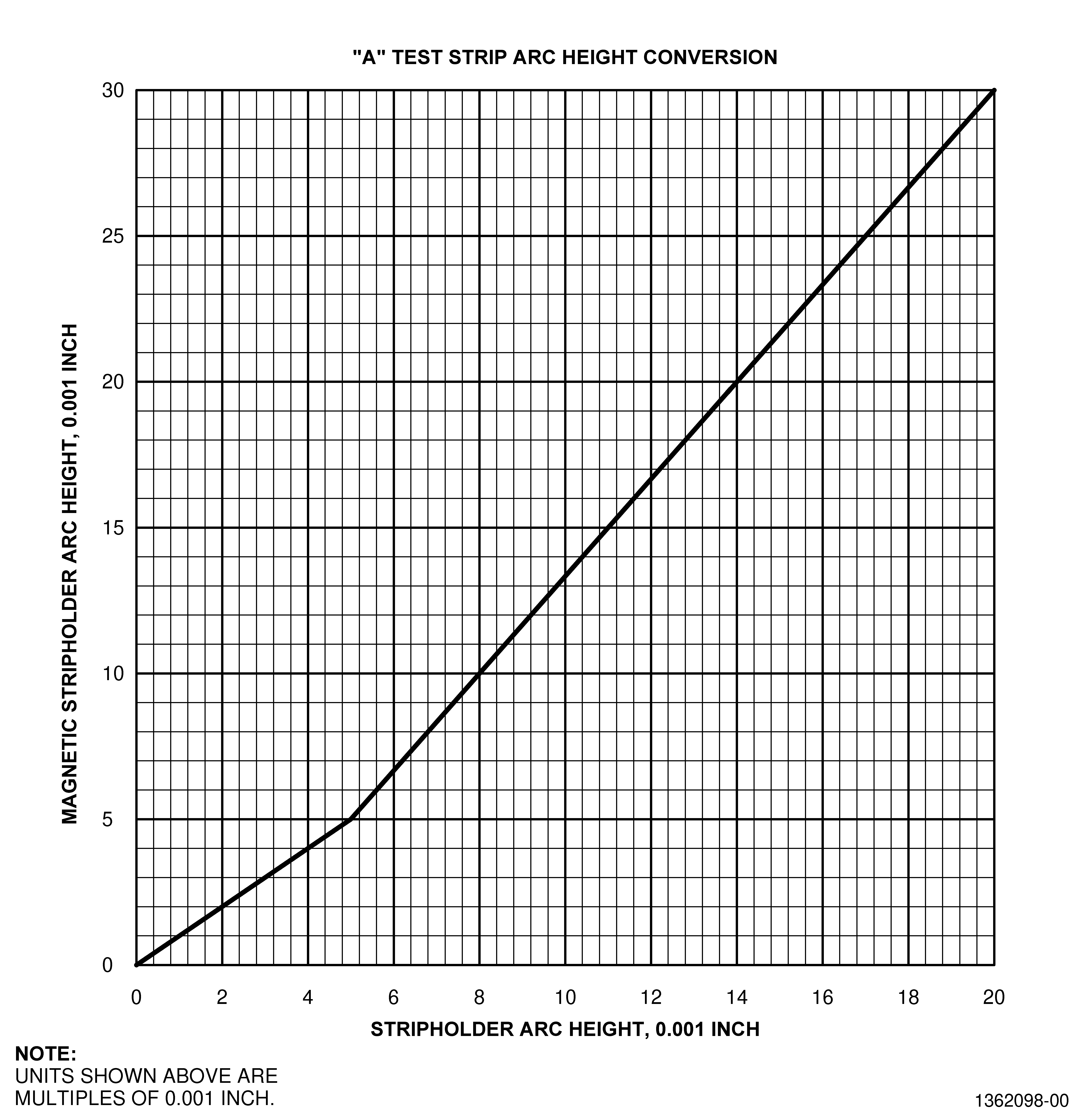
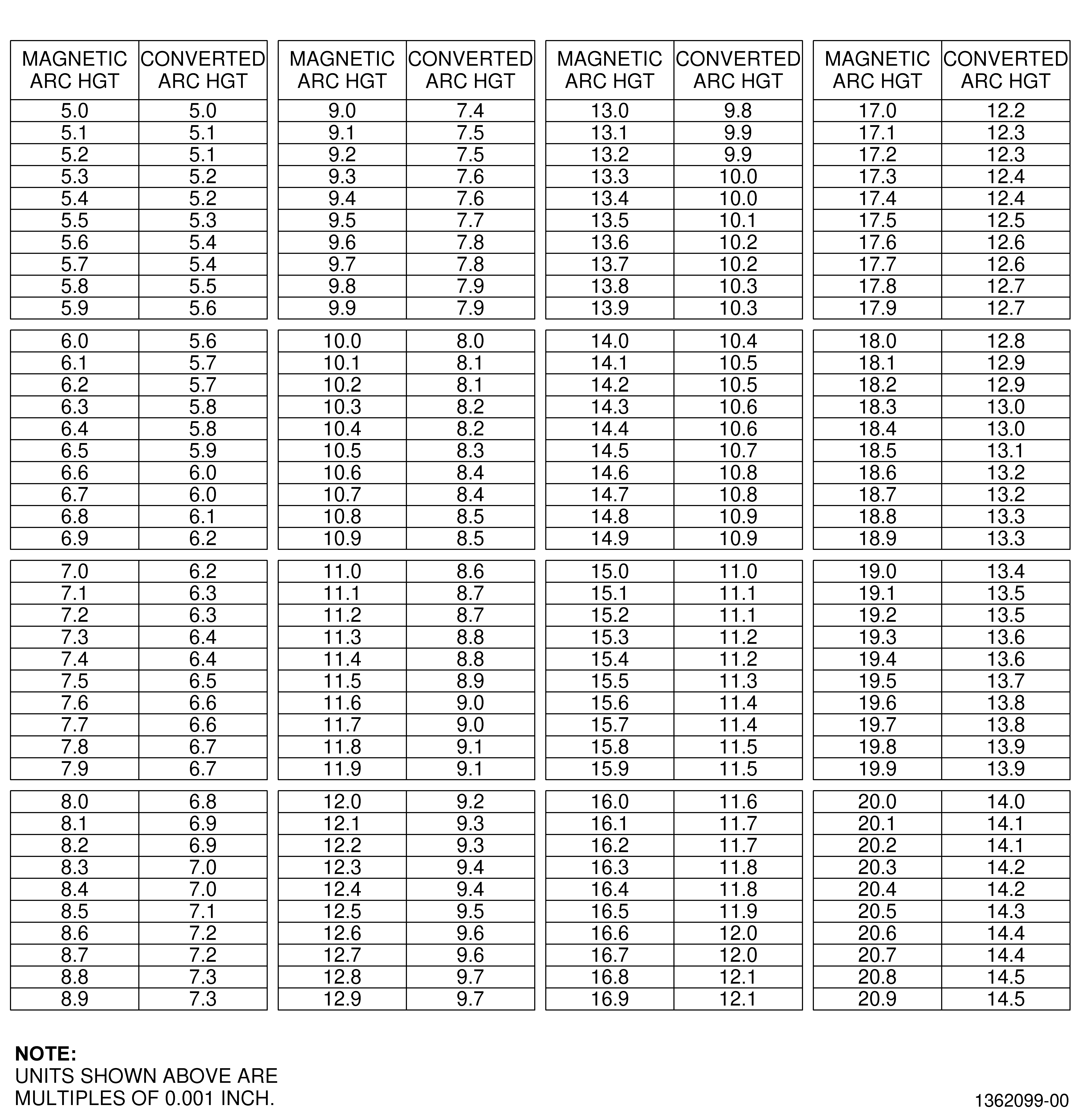
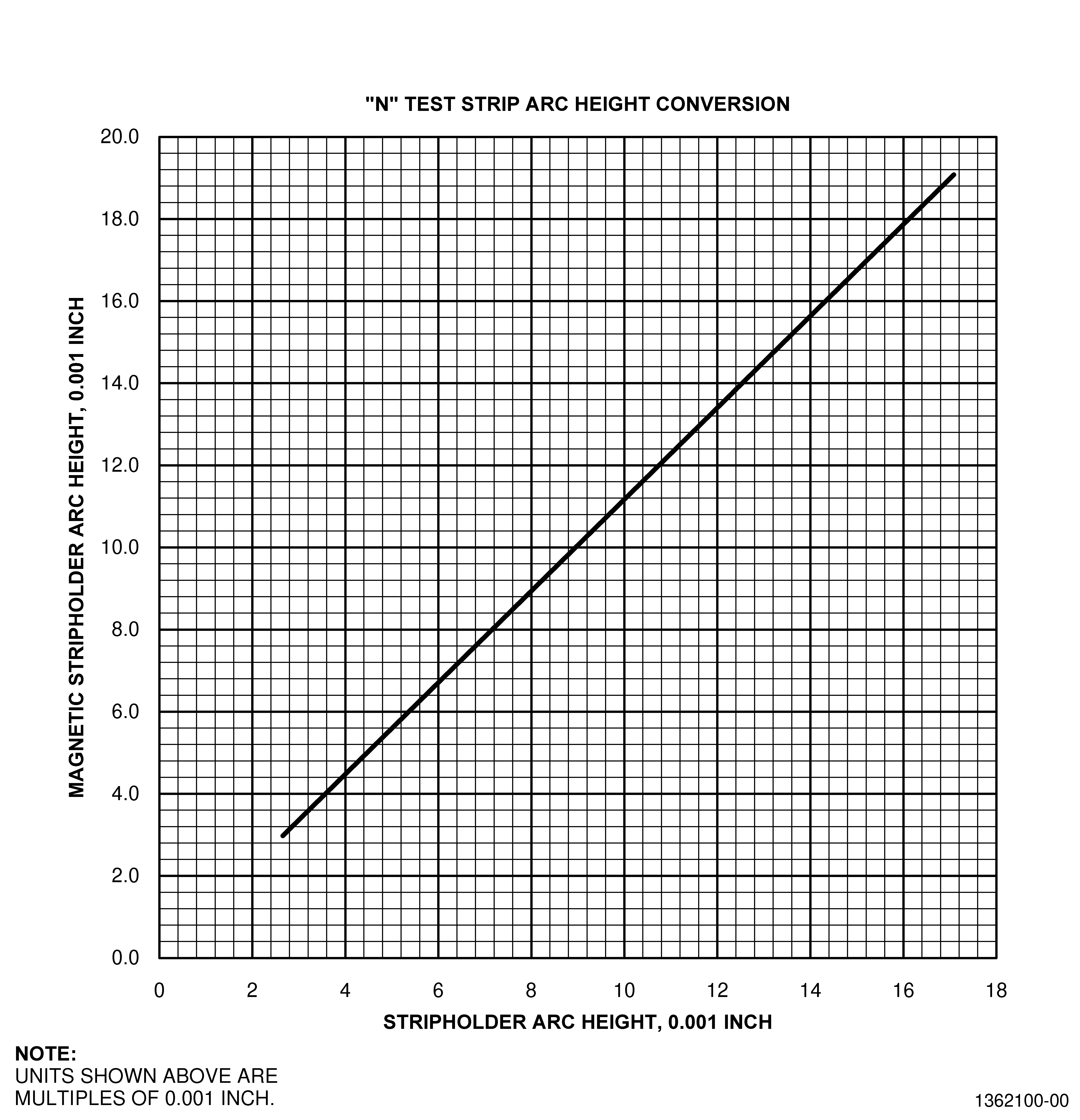
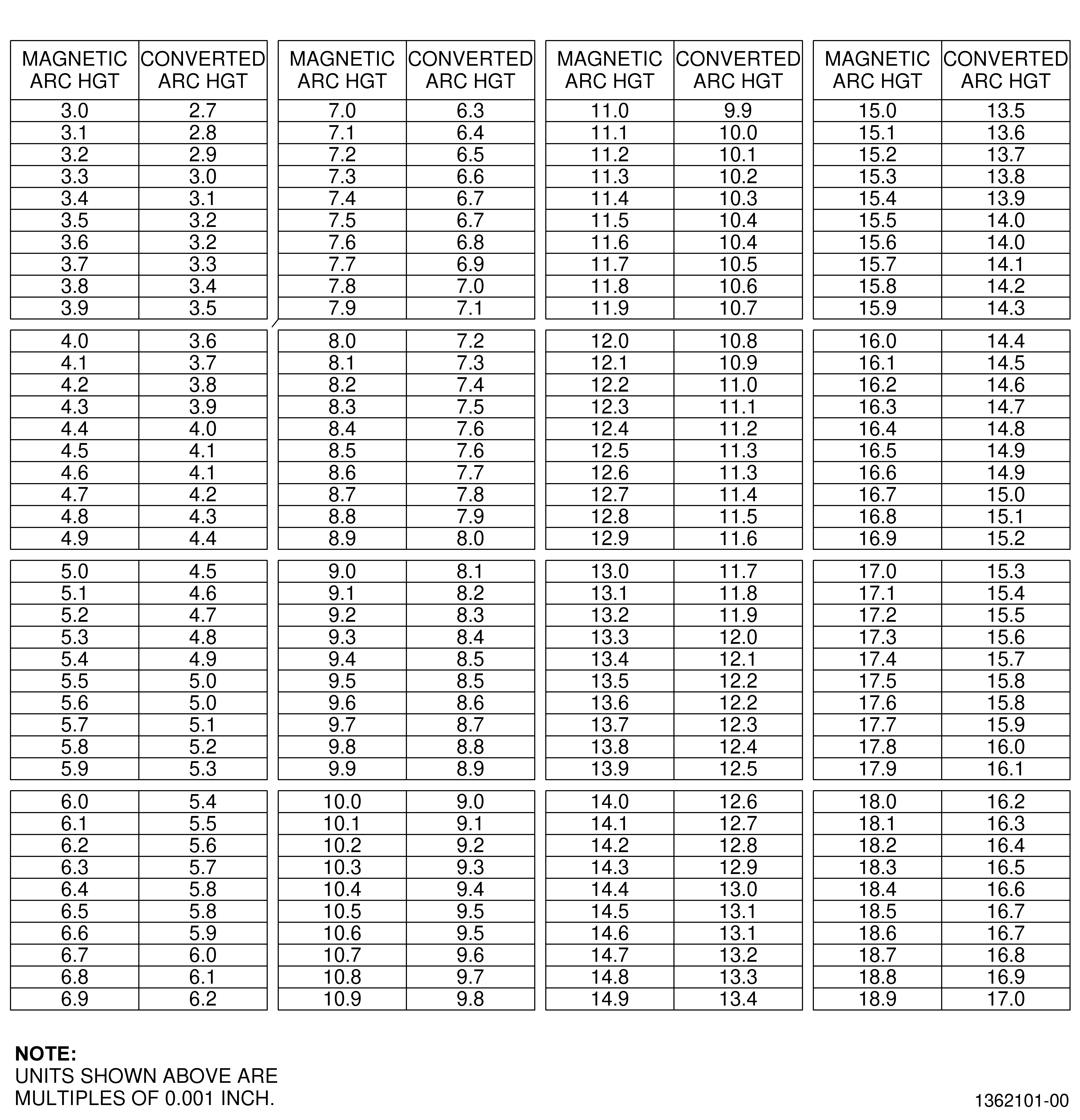
| (1) | Convert the required arc height in the Engine/Shop Manual. Use the conversion graphs/tables that follow: |
| (a) | For type A Almen test strips use Figure 7 or Figure 8. |
| (b) | For type N Almen test strips use Figure 9 or Figure 10. |
| NOTE: |
|
| NOTE: |
|
| NOTE: |
|
| (2) | Position an Almen test strip in the Almen gage and set the indicator to zero. Reverse the strip so that opposite surface is up and check for out-of-flatness. If out-of-flatness exceeds0.001 inch (0.03 mm), select a new strip and repeat the check. |
| (3) | Position strip in magnetic Almen strip holder. See Subtask 70-47-04-380-191, Equipment. |
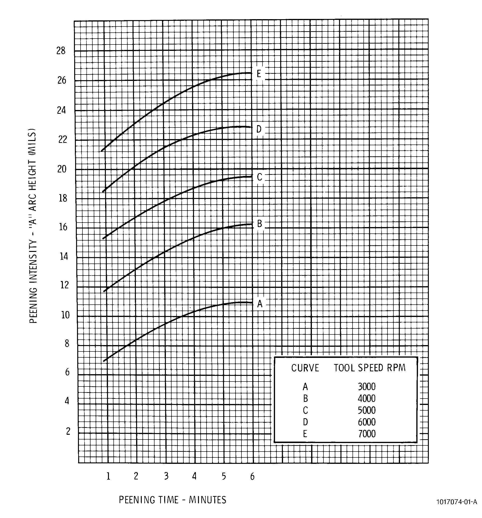
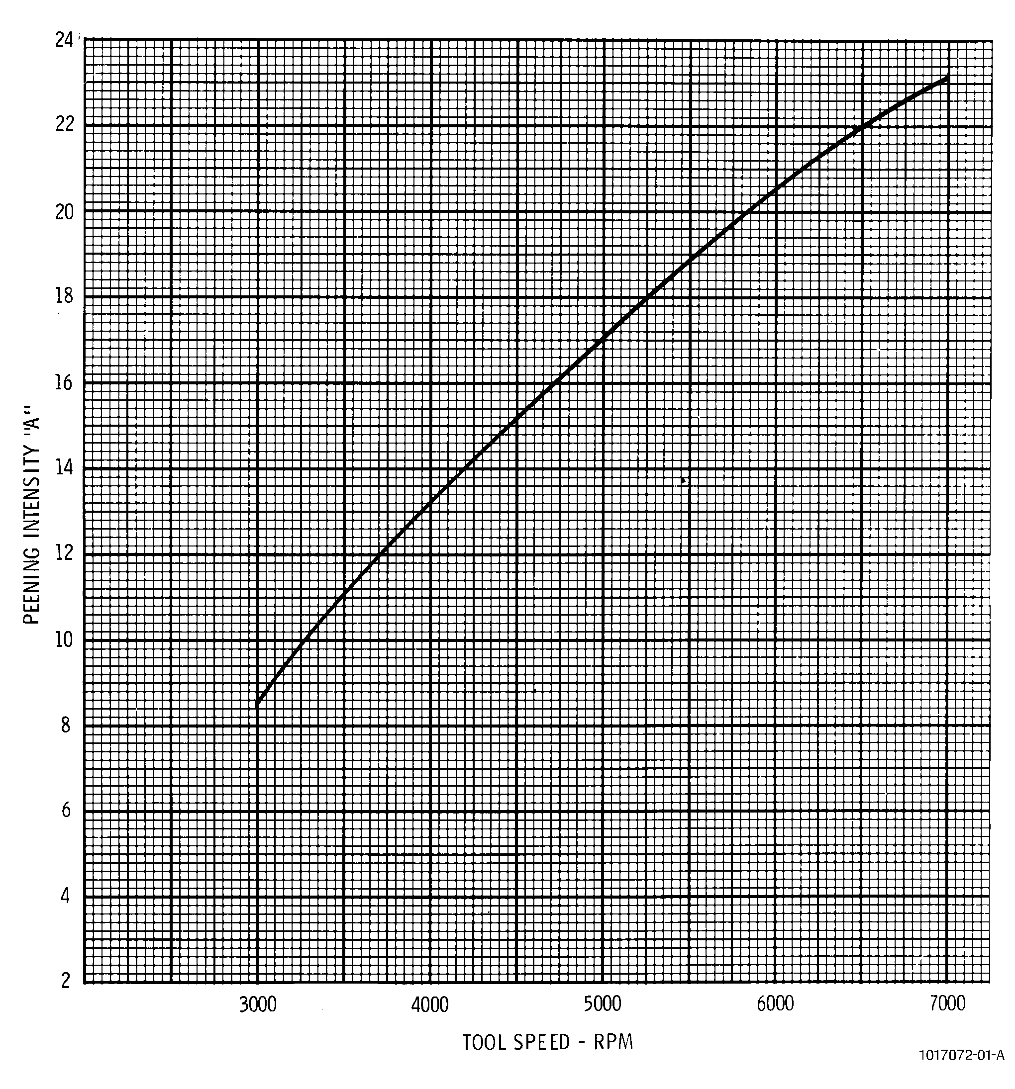
| (4) | Install and center flap assembly in mandrel with mandrel firmly attached in chuck of flexible shaft or hand operated grinder. Select an initial tool speed. Refer to Figure 6. |
| (5) | Alternative Procedure Available. Set tool speed under load and peen test strip along its entire length for a period of 2 minutes. |
| (5).A. | Alternative Procedure. Peening of the extreme ends of test strips is not necessary, and offers a significant time saving when generating saturation curves at low intensity. However, uniform coverage of at least the central 2.00 inches (50.8 mm) of length, for a period of 2 minutes is essential to ensure accurate arc height measurement across the Almen gage 1.25 inches (31.8 mm) support ball distance. |
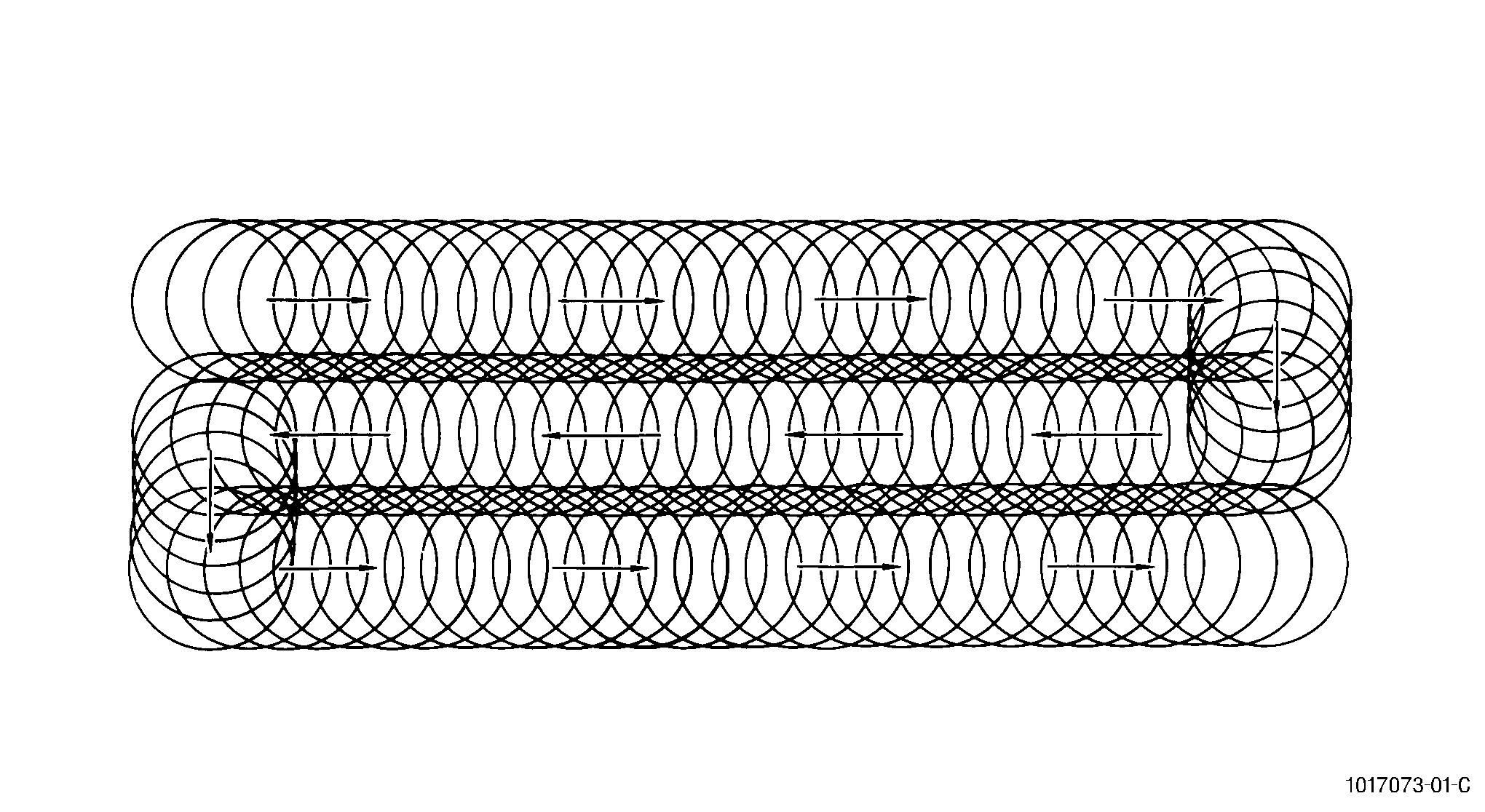
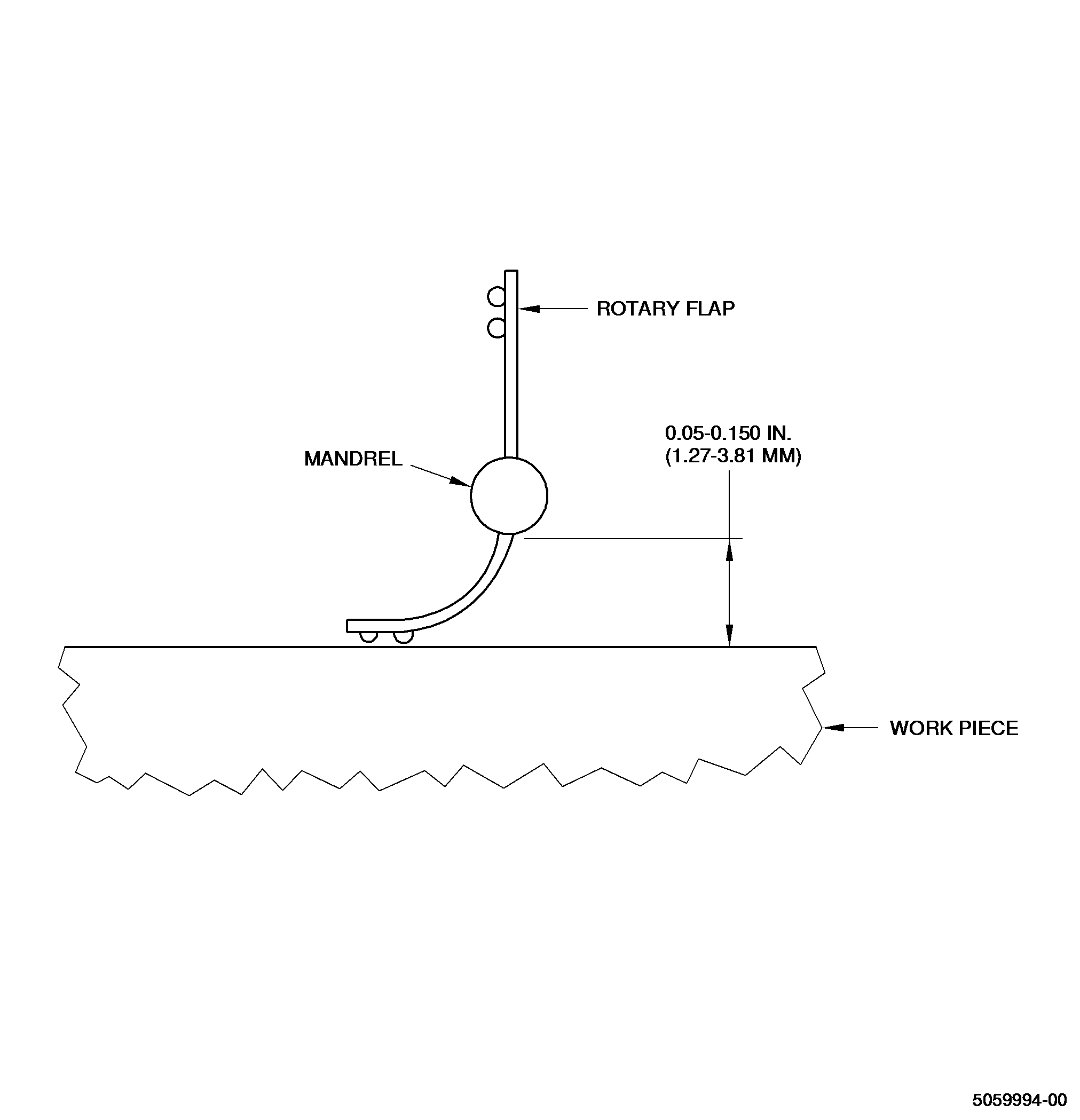
| (6) | Mandrel will be positioned parallel to and recommended flap deflection (standoff distance from the bottom of mandrel to part surface) must be between 0.050-0.150 inch (1.27-3.81 mm) of surface being peened. Refer to Figure 5. The tool or shaft must be moved continuously in an overlapping circular motion to maximize uniformity of coverage. Refer to Figure 4. |
| NOTE: |
|
| (7) | Determine Almen strip arc height by placing test strip on Almen gage and record reading. |
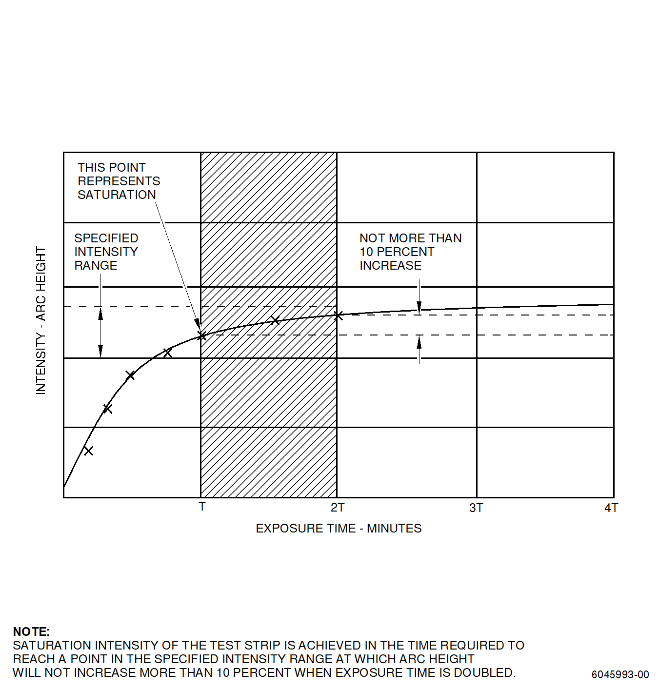
| (8) | Repeat steps Subtask 70-47-04-380-195, paragraph 4.B.(4) and Subtask 70-47-04-380-195, paragraph 4.B.(7) with the same test strip and generate a saturation curve plotting the converted arc heights. A minimum of four arc heights are necessary. Refer to Figure 2. |
| NOTE: |
|
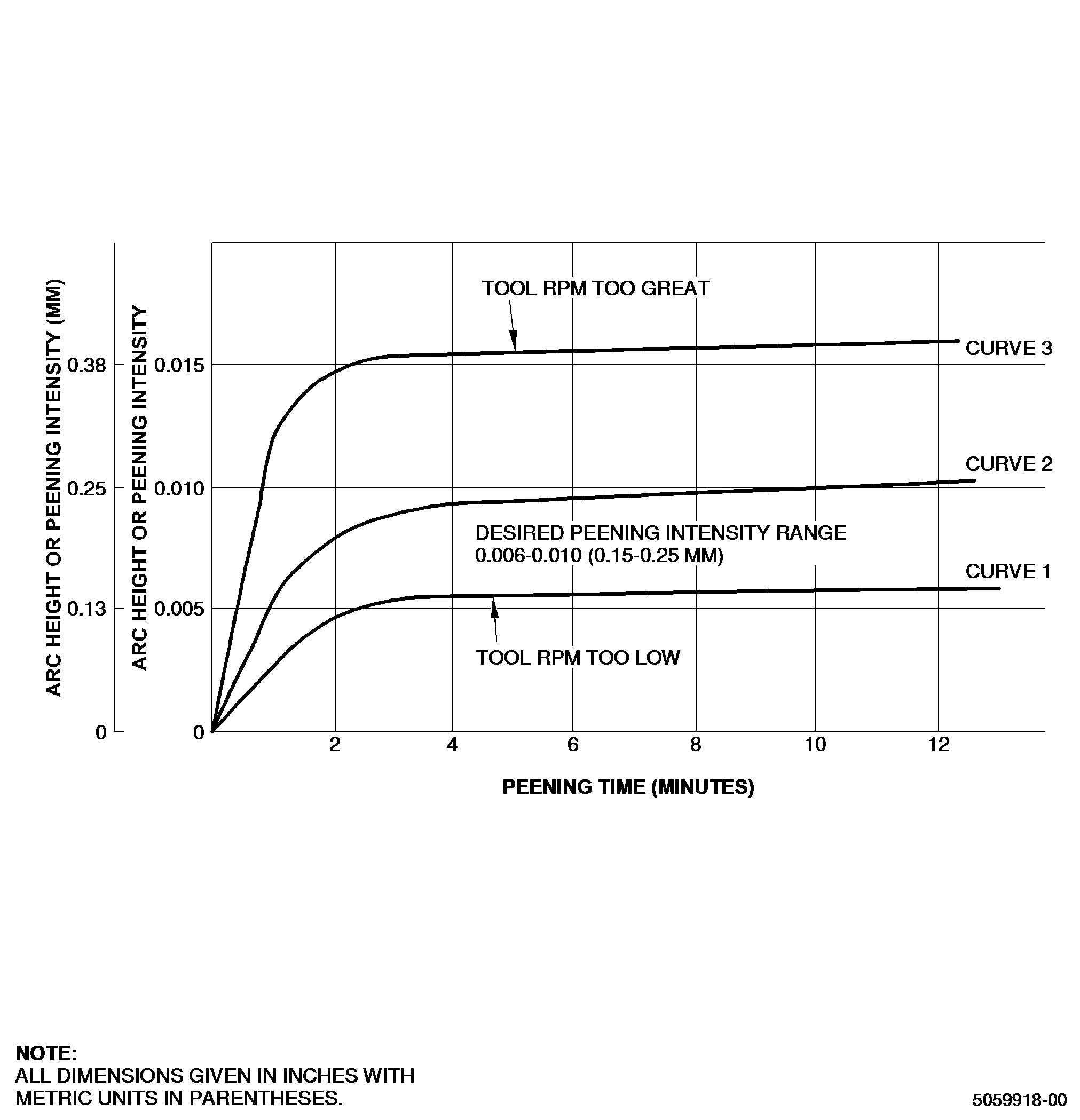
| (9) | If saturation point thus determined is not within intensity limits of part to be peened, set tool speed to a new setting(increase tool speed to increase intensity and vice-versa) and determine the new saturation curve. Repeat this procedure until adequate peening intensity, within limits specified by Engine/Shop Manual repair procedure is achieved. Refer to Figure 1. |
| (10) | Check for uniformity of coverage with a minimum of 10x power magnification. |
| (11) | Calculate peening time for repair parts by multiplying saturation time by 1.25 (125 percent) unless otherwise directed by applicable instructions for the parts. |
| NOTE: |
|
| Subtask 70-47-04-380-196 |
| F. | Peening Parts. |
| The following is intended for peening areas no larger than2 sq inches (12.9 sq cm). If the area to be peened is larger than2 sq inches (12.9 sq cm), it must be divided into sections, less than 2 sq inches (12.9 sq cm). Each section must be completely peened before proceeding to next section. Overlap at section boundaries is required. |
| (1) | If area to be peened is flat, position this area in a horizontal plane. If area is on a curved surface, position with approximate center of area uppermost for maximum accessibility. |
| (2) | Peen designated area on part with the same tool speed and technique used to establish saturation curve. Peening of part must be done by same operator who established peening parameters with test strips. |
| (3) | Periodically check rotary flap for missing balls. The loss of shot will affect coverage time, but not intensity. Replace flap if more than 2 balls are missing from either on one side. |
| 5 . | Quality Assurance. |
| Subtask 70-47-04-380-194 |
| G. | Establish peening requirements for intensity required each time a lot of similar parts is to be peened. Determine the peening requirements per Subtask 70-47-04-380-193, Procedure. |
| H. | Establish parameters each time operator is changed, such as shift change or job reassignment. |
| I. | At least one intensity determination or verification as defined in Subtask 70-47-04-380-195, Determination of Peening Requirements must be made prior to peening of part(s) to represent each tool and its equipment for each 30 minutes of continuous operation or fraction thereof, and for each change in intensity/RPM/Flap. Refer to Subtask 70-47-04-380-193, Procedure. |
| J. | Check peened area with a minimum of 10x power magnification to make sure that the coverage is complete. If coverage is not complete of individual indentations do not overlap, repeat the peening operation, refer to Subtask 70-47-04-380-196, Peening Parts. Holes must be inspected with a suitable optical instrument. Refer to Subtask 70-47-04-380-193, Procedure. |