| COMMERCIAL ENGINE STANDARD PRACTICES MANUAL | Dated: 03/08/2023 | |
| SPM 70-42-00 BLENDING AND REMOVAL OF HIGH METAL PROCEDURES | ||
| COMMERCIAL ENGINE STANDARD PRACTICES MANUAL | Dated: 03/08/2023 | |
| SPM 70-42-00 BLENDING AND REMOVAL OF HIGH METAL PROCEDURES | ||
| TASK 70-42-00-350-002 |
| 1 . | General. |
| NOTE: |
|
| A. | Blending is a repair procedure that is used to remove stress concentrations caused by nicks, scratches, or other sharp-edged damage marks on critical parts. Removal of the material surrounding the stress concentration, so that the sharp edges are blended into a smooth contour, relieves the stress concentration and permits further use of the part by lessening the danger of cracking. |
| NOTE: |
|
| B. | Blending is also used to remove sharp edges resulting from machining, drilling, etc., and to restore the original contour and/or surface finish to parts that have been repaired by welding, brazing, etc. |
| C. | Defects more then 0.25 inch (6.4 mm) apart shall be blended separately. Those less than 0.25 inch (6.4 mm) apart (except splines) shall be blended together. Splines that are closer together than 0.25 inch (6.4 mm) and defects shall be repaired separately. |
| D. | The finish on the blended area must be as close as possible to the original finish of the part. |
| E. | Linear Indication is defined as a visual surface indication that has a linear length three times its width or greater. The maximum allowable indication size is defined in the ‘Fluorescent Penetrant Inspection’ and/or the ‘Visual Inspection’ section of the Engine Inspection Manual for that part. |
| F. | Removal of High Metal is addressed in several paragraphs, make sure you use the correct procedure for your component as follows: |
| (1) | General Removal of High Metal (No Shot Peening), refer to Subtask 70-42-00-350-029, (paragraph 4.D.). |
| (2) | Rotating part high metal removal (like disks, shafts, boosters, blisks, impellers, spools, disk like seals, cooling plates, spacers thermal shields, torque couplings and main rotor shafts) refer to Subtask 70-42-00-350-038, (paragraph 4.C.(3)(e)). This subtask requires FPI and shot peening after high metal removal. |
| 2 . | Equipment. |
| Subtask 70-42-00-350-025 |
| A. | The following tools are required for the application of this process. |
| (1) | Standard Tools - Blending: 3 - 10X Magnifying Glass |
| (2) | Power Blending: Power Tool (Electric Or Air) |
| (3) | Manual Blending: Files (Assorted) |
| 3 . | Materials. |
| Subtask 70-42-00-350-026 |
| A. | The following consumable materials are required for the application of this process. |
| 4 . | Procedure. |
| Subtask 70-42-00-350-021 |
| A. | Manual (Hand) Blending. |
| WARNING: |
|
| (1) | Sharp edges can be blended out, using abrasive stones or papers, files, or crocus cloth. Coarse grades of abrasives or files may be used for fast metal removal, but the parts must then be given a smooth surface finish with fine grades of abrasives or crocus cloth. |
| (a) | When blending compressor rotor blades, stator vanes, turbine blades, and similar parts, blend in a radial direction in relation to the engine. Avoid removing metal from leading and trailing edges of airfoil sections in such a way that the edges become thin or sharp; blend so as to maintain approximately the original contour. |
| NOTE: |
|
| (b) | When blending a cylindrical part, blend in a circumferential direction, not along the axis of the part. |
| (c) | The finish on the blended area must be as close to the original finish as possible. |
| (d) | When blending on a part involving a radius, keep the radius as specified in the repair section. If the radius is not specified, keep it as close as possible to the original contour. Refer to a similar part, if necessary to determine original radius. |
| (e) | After blending, etch the reworked area per TASK 70-24-00-110-033, Etching Procedures for Fluorescent-Penetrant Inspection. Inspect per TASK 70-32-03-230-002, Spot-Fluorescent-Penetrant Inspection. |
| Subtask 70-42-00-350-027 |
| B. | Power Blending. |
| WARNING: |
|
| CAUTION: |
|
| (1) | Blending on most parts may be done by using a power-driven polishing wheel or rubber-bonded abrasive points. Special instructions for the individual part must be followed. |
| CAUTION: |
|
| (a) | Rough-out defects using coarse grades of resilient flexible abrasive impregnated wheels, brushes, or points. Use fine or extra fine grades to finish the blend areas. |
| (b) | When doing power blending, follow the requirements described in Subtask 70-42-00-350-021, Hand-Blending. |
| NOTE: |
|
| (c) | After blending, etch the reworked area per TASK 70-24-00-110-033, Etching Procedures for Fluorescent-Penetrant Inspection. Inspect per TASK 70-32-03-230-002, Spot-Fluorescent-Penetrant Inspection. |
| Subtask 70-42-00-350-028 |
| C. | Component Specific Requirements. |
| WARNING: |
|
| (1) | Blending Airfoils. |
| NOTE: |
|
| (a) | The types of airfoil damage described below may be repaired by hand-blending or by power-blending. Always refer to applicable part inspection paragraph for a description of airfoil defect limits as follows: |
| 1 | Nick. A V-shaped depression in the airfoil made by a sharp-edged object pushing the metal inward. |
| 2 | Pit. A round, sharp-edged hole with a rounded bottom caused by corrosion. |
| 3 | Scratch. A V-shaped line or furrow in the airfoil, such as would be made by dragging a sharp object across the surface. |
| 4 | Dent. A smooth, rounded depression in the airfoil made by impact with a rounded object. If there is a noticeable sharp discontinuity in the depression, it should be considered a nick. Waviness of leading or trailing edge is to be treated as a dent. |
| 5 | Erosion. A sand- or shot-blasting effect on the leading edges or the leading portion of the concave side, caused by sand or dust going through the engine. |
| 6 | Torn Metal. A separation or pulling apart of material by force, leaving jagged edges. |
| (b) | Hand-blending of airfoils may be done as specified below: |
| 1 | Blending is done to remove stress caused by nicks, pits and scratches to prevent blade failure. Remove high metal and straighten dents (where permitted) to restore the airfoil shape as closely as possible to its original aerodynamic contour. |
| 2 | Blending shall be finished with fine stone or crocus cloth. Coarser tools may be used for the initial removal of material. Finish the blending in a direction along the length of the blade or vane, and remove all evidence of marks across the airfoil that may have been made during initial blending. |
| 3 | Defects more than 0.25 in (6.4 mm) apart shall be blended separately; those 0.25 in (6.4 mm) or less apart may be blended together. All blends must have a minimum radius of 0.25 in (6.4 mm). The total reduction in chord width may be taken on either side or divided between the sides. The amount of rework is controlled by the minimum chord width limit. The minimum allowable chord is given for the root and tip of airfoil, and the minimum chord at other points is proportional. |
| To minimize the possibility of having the engine stall, keep the shape of the blended airfoil leading edge as close as possible to the original contour. Refer to Figure 1. |
| 4 | Blending limits are given as depth dimensions to make it easier to see how much can be repaired. Experience has shown that depth limits are used for most rework. However, the minimum chord limit is the most important dimension; it should be checked in borderline cases or where previous rework is evident in the same area. For convenience, the depth limits and minimum chord limits are given in both decimals and fractions. In borderline cases where depth limits and minimum chord limits conflict with one another, use the decimal minimum chord dimension to decide if the part is usable. |
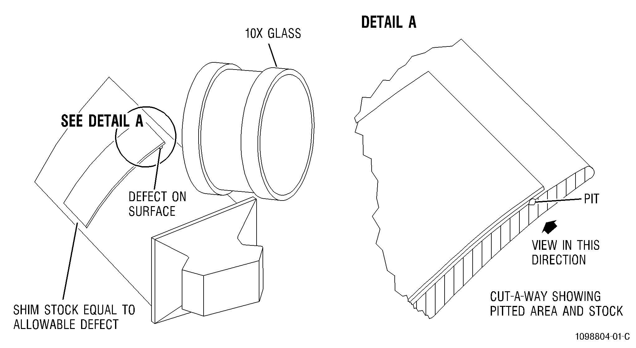
| 5 | Defect limits are given as depth dimensions since this is the dimension that affects strength. However, accurate depth measurements require special equipment not normally available. Comparing the depth of a defect with the thickness of a thickness gage leaf, or with the thickness of a piece of safety wire, is a reasonably accurate way of measuring depth. Refer to Figure 2. |
| 6 | Swab-etch the reworked area per TASK 70-24-00-110-033, Etching Procedures for Fluorescent-Penetrant Inspection. Inspect per TASK 70-32-03-230-002, Spot-Fluorescent-Penetrant Inspection. Brush or swab on penetrant where air passages are present, to prevent excessive penetrant entrapment. |
| (c) | Power-blending of rotor blades, variable vanes, and vane segments may be done as follows: |
| 1 | To avoid damaging the airfoil, use masking tape and mask off the airfoil next to the rework area. |
| 2 | Use coarse grade, silicon-carbide-impregnated rubber wheels and points for the initial benching of the blades and vanes. |
| NOTE: |
|
| 3 | Finish blending the defects, using the fine and extra fine grade of rubberized abrasive wheels. Remove only enough material to repair the defect. |
| 4 | Swab-etch the reworked areas per TASK 70-24-00-110-033, Etching Procedures for Fluorescent-Penetrant Inspection. Inspect per TASK 70-32-03-230-002, Spot-Fluorescent-Penetrant Inspection. |
| 5 | Place the repaired blades and vanes in separate containers to prevent damage during handling. |
| 6 | Carefully inspect the blades and vanes. |
| (2) | Blending Minor Indications in Tubing. |
| (a) | Use a fine abrasive stone, a small needle file with fine teeth, emery cloth, or crocus cloth for blending. |
| (b) | Blend around the circumference of the tubing. The finished blend shall be as close as practical to the original finish of the part. |
| Subtask 70-42-00-350-030 |
| (3) | Blending And Shot Peening of Rotating Parts - Forged and Powdered Metal Components. |
| NOTE: |
|
| CAUTION: |
|
| NOTE: |
|
| NOTE: |
|
| NOTE: |
|
| NOTE: |
|
| NOTE: |
|
| NOTE: |
|
| NOTE: |
|
| NOTE: |
|
| (a) | General Specifications. |
| 1 | The preferred blend shape is smooth, continuous, and round-bottomed, extending as far as necessary from the damaged area. Refer to Figure 4. |
| NOTE: |
|
| Subtask 70-42-00-350-031 |
| 2 | Size, Separation, and Location of Blends. |
| a | A single blend is preferred when the blending of adjacent damage would result in intersecting or nearly intersecting blends. |
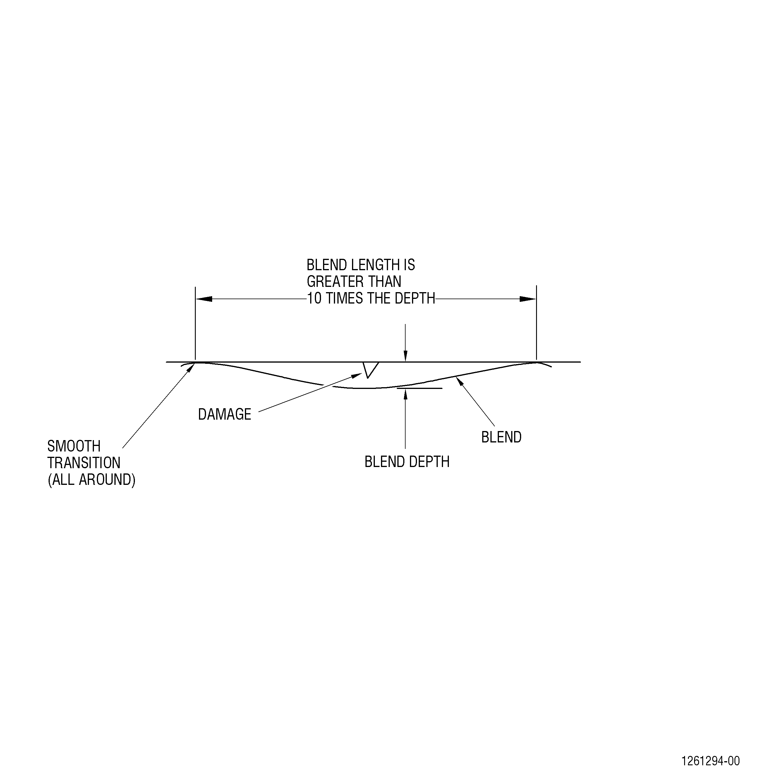
| b | The length of the blend must be a minimum of 10 times the depth of the blend in all directions, if the local surface area allows, larger length to depth ratios are preferable. Blend to approximately 1.25 times (for reference only) the depth of the damage. Refer to Table 1 and Figure 4. Remove all sharp edges. Blend depth is not to exceed the Engine Inspection Manual limits after blending. |
| Subtask 70-42-00-350-032 |
| 3 | Direction of Blends. |
| a | When blending a cylindrical part, blend in a circumferential direction, not along the axis of the part, unless the damage is radially oriented. |
| b | Damage that is radially oriented must be blended in a radial direction. |
| c | When blending a feature that involves a radius, shape the radius as specified in the repair section. If the radius is not specified, shape it as close as possible to the original contour. Refer to an undamaged location in the feature or a similar part if necessary to determine original radius. |
| NOTE: |
|
| Subtask 70-42-00-350-033 |
| 4 | Finish of Blends. |
| a | If the blended area intersects a corner, break the sharp edges to those specified in the Engine Inspection Manual for that feature. If not specified, use one of two options: Option 1: blend the corner to a radius of 0.015-0.030 inch (0.38-0.76 mm), Option 2: blend to match the general radius of the corner. Refer to a nearby, non-blended location of the corner or a similar part if necessary to determine original radius. |
| b | If the blended area intersects a curved feature, restore the general shape of the original contour. Refer to a nearby, non-blended location of the feature or a similar part if necessary to determine the original contour. |
| c | All transitions from blended to non-blended areas must be smooth and continuous. |
| d | The surface finish of the blended area must be as smooth as or smoother than adjacent non-blended surfaces. Polishing is optional. |
| Subtask 70-42-00-350-034 |
| 5 | Blending Guidelines. Refer to Figure 4. |
|
| NOTE: |
|
| NOTE: |
|
| Subtask 70-42-00-350-035 |
| (b) | Titanium Blending - (Rotating Parts). |
| WARNING: |
|
| WARNING: |
|
| CAUTION: |
|
| CAUTION: |
|
| CAUTION: |
|
| CAUTION: |
|
| CAUTION: |
|
| CAUTION: |
|
| CAUTION: |
|
| NOTE: |
|
| 1 | Blend per ‘General Specifications’ section specified in Subtask 70-42-00-350-030 (paragraph C.(3).(a)). Either the ‘Manual Blending Procedure’ Subtask 72-42-00-350-036 (paragraph C.(3).(c) or the ‘Power Blending Procedure’ Subtask 72-42-00-350-036 (paragraph C.(3).(d) may be used. |
| a | If the ‘Power Blending Procedure’ was used, manually remove an additional 0.002 inch (0.05 mm). Final blend depth must be within the limits specified in the Engine Inspection Manual after blending. |
| 2 | Examine the blend area for any signs of overheating (discoloration). |
| a | Overheating (discoloration) is not permitted. |
| 3 | Clean the part again, if necessary, in preparation for Fluorescent Penetrant Inspection, refer to Engine Inspection Manual cleaning section for directions for that part. |
| 4 | Swab-etch the blended area. Refer to TASK 70-24-01-110-034, Swab Etching Procedure and refer to the Class specified in the Engine Inspection Manual for that part. |
| 5 | Do a spot Fluorescent Penetrant Inspection. Refer to TASK 70-32-03-230-002, Spot-Fluorescent-Penetrant Inspection of the blended area. Refer to the Fluorescent Penetrant Inspection Class specified in the Engine Inspection Manual for that part. No relevant linear indications allowed. If guidance is needed, contact GE Aviation ‘Customer Support Center’ (email: geae.csc@ae.ge.com) or ‘Product Support Engineering’ for specifications. |
| 6 | Clean the part after all Fluorescent Penetrant Inspection’s are completed. Refer to TASK 70-32-02-230-001 , Fluorescent Penetrant Inspection, paragraph 6.D.(3), ‘Cleaning of Parts After Inspection’. |
| CAUTION: |
|
| 7 | Do a shot peen of the blended areas. Refer to TASK 70-47-01-380-016, Shotpeening. Follow the shot peen requirements specified for the blended area by using the appropriate Repair Procedure, Service Bulletin, or engine manual Inspection Section. If no shot peen procedure is specified, use the following shot peen parameters: use CCW 14 or S110 shot with an intensity of 6-12N, verified with Type N Test Almen strips (as noted in TASK 70-47-01-380-016, Shotpeening, paragraph 4.E., Intensity Determination). Do not over peen. Mask areas that do not require shot peening with plastic tape (C10-021). |
| NOTE: |
|
| Subtask 70-42-00-350-036 |
| (c) | Manual Blending Procedure (Hand Blending Method) (Rotating Parts). |
| WARNING: |
|
| 1 | Manually blend to a minimum length of 10 times the depth of the blend in all directions, if the local surface area allows, larger length to depth ratios are preferable. Blend to approximately 1.25 times (for reference only) the depth of the damage. Refer to Table 1 and Figure 4. Remove all sharp edges. Blend depth is not to exceed the Engine Inspection Manual limits after blending. |
| 2 | Use typical abrasive tools. Refer to the Consumable Materials List. |
| 3 | To keep abrasives working properly, do not permit the abrasive to become loaded up with removed material. |
| 4 | Start the blend with coarser grades of abrasives or files for fast initial removal of damage but not coarser than needed to remove the damage. |
| 5 | Finish the blends with the finer grades of abrasives or crocus cloths until the surface is as smooth as or smoother than the adjacent surfaces. |
| 6 | Clean the part again, if necessary in preparation for Fluorescent Penetrant Inspection; refer to Engine Inspection Manual cleaning section for directions for that part. |
| 7 | Swab etch the blended area. Refer to TASK 70-24-01-110-034, Swab Etching Procedure. |
| 8 | Do a spot Fluorescent Penetrant Inspection. Refer to TASK 70-32-03-230-002, Spot-Fluorescent-Penetrant Inspection of the blended area. Refer to the Fluorescent Penetrant Inspection Class specified in the Engine Inspection Manual for that part. No relevant linear indications allowed. If guidance is needed, contact GE Aviation ‘Customer Support Center’ (email: geae.csc@ae.ge.com) or ‘Product Support Engineering’ for specifications. |
| 9 | Clean the part after all Fluorescent Penetrant Inspection’s are completed. Refer to TASK 70-32-02-230-001 , Fluorescent Penetrant Inspection, paragraph 6.D.(3), ‘Cleaning of Parts After Inspection’. |
| 10 | Do a shot peen of the blended areas. Refer to TASK 70-47-01-380-016, Shotpeening. Follow the shot peen requirements specified for the blended area by using the appropriate Repair Procedure, Service Bulletin, or engine manual Inspection Section. If no shot peen procedure is specified, use the following shot peen parameters: use CCW 14 or S110 shot with an intensity of 6-12N, verified with Type N Test Almen strips (as noted in TASK 70-47-01-380-016, Shotpeening, paragraph 4.E., Intensity Determination). Do not over peen. Mask areas that do not require shot peening with (C10-021) plastic tape. |
| NOTE: |
|
| Subtask 70-42-00-350-037 |
| (d) | Power Blending Procedure (Rotating Parts). |
| WARNING: |
|
| CAUTION: |
|
| 1 | Blend per the ‘General Specifications’ section specified in Subtask 70-42-00-350-030 (paragraph C.(3).(a)). |
| 2 | Use typical abrasive tools. Refer to the ‘Materials’ section. |
| 3 | To keep abrasives working properly, do not permit the abrasive to become loaded up with removed material. |
| 4 | Do not overheat or cause any discoloration to the part. Use only minimum pressure when you apply power blending tools to parts. Overheating of parts during blending can cause damage or reduce the mechanical properties of the part. |
| a | Overheating (discoloration) is not permitted. |
| 5 | Blend with the tools and the sequence that follows. |
| a | Start the power blend with coarser grades of resilient flexible abrasive impregnated wheels, brushes or points for the initial removal of damage but not coarser than needed to remove the damage. |
| b | Finish the blend with the finer grades of abrasives or crocus cloth until the surface is as smooth as or smoother than the adjacent surfaces. |
| 6 | If necessary, polish the blend, refer to Subtask 70-42-00-350-033 (paragraph C.(3).(a)4). ‘Finish of Blends’, using a polishing wheel and polishing compound, use Polishing Compound 240 grit aluminum oxide in soft grease or equivalent. |
| 7 | Clean the part again, if necessary in preparation for Fluorescent Penetrant Inspection. Refer to Engine Inspection Manual cleaning section for directions for that part. |
| 8 | Swab-etch the reworked area. Refer to TASK 70-24-01-110-034, Swab Etching Procedure and refer to the Class specified in the Engine Inspection Manual for that part. |
| 9 | Do a spot Fluorescent Penetrant Inspection. Refer to TASK 70-32-03-230-002, Spot-Fluorescent-Penetrant Inspection of the reworked area. Refer to the Fluorescent Penetrant Inspection Class specified in the Engine Inspection Manual for that part. No relevant linear indications allowed. If guidance is needed, contact GE Aviation ‘Customer Support Center’ (email: geae.csc@ae.ge.com) or ‘Product Support Engineering’ for specifications. |
| 10 | Clean the part after all Fluorescent Penetrant Inspection’s are completed. Refer to TASK 70-32-02-230-001 , Fluorescent Penetrant Inspection, paragraph 6.D.(3), ‘Cleaning of Parts After Inspection’. |
| CAUTION: |
|
| 11 | Do a shot peen of the blended areas. Refer to TASK 70-47-01-380-016, Shotpeening. Follow the shot peen requirements specified for the blended areas by using the appropriate Repair Procedure, Service Bulletin, or engine manual Inspection Section. If no shot peen procedure is specified, use the following shot peen parameters: use CCW 14 or S110 shot with an intensity of 6-12N, verified with Type N Test Almen strips (as noted in TASK 70-47-01-380-016, Shotpeening, paragraph 4.E., Intensity Determination). Do not over peen. Mask areas that do not require shot peening. |
| NOTE: |
|
| Subtask 70-42-00-350-038 |
| (e) | High Metal Removal Procedure (Rotating Parts). |
| NOTE: |
|
| NOTE: |
|
| 1 | Remove high metal as follows: |
| a | Use a fine abrasive stone, emery cloth, or crocus cloth to remove high metal. |
| b | Remove only the material that is projecting above the original surface contour. |
| c | Finish the blend with the finer grades of abrasives or crocus cloth until the surface is as smooth as or smoother than the adjacent surfaces. Polishing is optional. |
| 2 | Clean the part again, if necessary in preparation for Fluorescent Penetrant Inspection. Refer to engine manual cleaning section for directions for that part. |
| 3 | Swab-etch the reworked area. Refer to TASK 70-24-01-110-034, Swab Etching Procedure and refer to the Class specified in the Engine Inspection Manual for that part. |
| 4 | Do a spot Fluorescent Penetrant Inspection. Refer to TASK 70-32-03-230-002, Spot-Fluorescent-Penetrant Inspection of the reworked area. Refer to the Fluorescent Penetrant Inspection Class specified in the Engine Inspection Manual for that part. No relevant linear indications allowed. If guidance is needed, contact GE Aviation ‘Customer Support Center’ (email: geae.csc@ae.ge.com) or ‘Product Support Engineering’ for specifications. |
| 5 | Clean the part after all Fluorescent Penetrant Inspection’s are completed. Refer to TASK 70-32-02-230-001 , Fluorescent Penetrant Inspection, paragraph 6.D.(3), ‘Cleaning of Parts After Inspection’. |
| CAUTION: |
|
| 6 | Do a shot peen of the blended areas. Refer to TASK 70-47-01-380-016, Shotpeening. Follow the shot peen requirements specified for the blended area by using the appropriate Repair Procedure, Service Bulletin, or engine manual Inspection Section. If no shot peen procedure is specified, use the following shot peen parameters: use CCW 14 or S110 shot with an intensity of 6-12N, verified with Type N Test Almen strips (as noted in TASK 70-47-01-380-016, Shotpeening, paragraph 4.E., Intensity Determination). Do not over peen. Mask areas that do not require shot peening with (C10-021) plastic tape. |
| NOTE: |
|
| Subtask 70-42-00-350-039 |
| (f) | Corrosion Pitting Rework Procedure (Rotating Parts). |
| CAUTION: |
|
| NOTE: |
|
| 1 | Wet blast clean the effected area. Refer to TASK 70-21-05-120-A02, Wet Abrasive Blast Cleaning Method No. 5A or, alternate TASK 70-21-05-120-B02, Wet Abrasive Blast Cleaning Method No. 5B, using 500 grit. Mask areas in close proximity that are not affected. |
| a | Make sure that the corrosion products are removed. Measure the depth of remaining pitting and make sure that it is acceptable. Refer to the limits noted in the engine inspection manual. If the corrosion limits are not specified in the engine manual, then contact ‘GE Aviation Customer Support Center’ for clarification. |
| 2 | Clean the part again, if necessary in preparation for Fluorescent Penetrant Inspection. Refer to engine manual cleaning section for directions for that part. |
| 3 | Swab-etch the affected area. Refer to TASK 70-24-01-110-034, Swab Etching Procedure and refer to the Class specified in the Engine Inspection Manual for that part. |
| 4 | Do a spot Fluorescent Penetrant Inspection. Refer to TASK 70-32-03-230-002, Spot-Fluorescent-Penetrant Inspection of the reworked area. Refer to the Fluorescent Penetrant Inspection Class specified in the Engine Inspection Manual for that part. No relevant linear indications allowed. If guidance is needed, contact GE Aviation ‘Customer Support Center’ (email: geae.csc@ae.ge.com) or ‘Product Support Engineering’ for specifications. |
| 5 | Clean the part after all Fluorescent Penetrant Inspection’s are completed. Refer to TASK 70-32-02-230-001 , Fluorescent Penetrant Inspection, paragraph 6.D.(3), ‘Cleaning of Parts After Inspection’. |
| CAUTION: |
|
| 6 | Before shot peen, measure the depth of remaining pitting and make sure that it is acceptable. Refer to the limits noted in the engine inspection manual. If the corrosion limits are not specified in the engine manual, then contact ‘GE Aviation Customer Support Center’ for clarification. |
| 7 | Do a shot peen of the affected areas. Refer to TASK 70-47-01-380-016, Shotpeening. Follow the shot peen requirements specified for the affected area by using the appropriate Repair Procedure, Service Bulletin, or engine manual Inspection Section. If no shot peen procedure is specified, use the following shot peen parameters: use CCW 14 or S110 shot with an intensity of 6-12N, verified with Type N Test Almen strips (as noted in TASK 70-47-01-380-016, Shotpeening, paragraph 4.E., Intensity Determination). Do not over peen. Mask areas that do not require shot peening with (C10-021) plastic tape. |
| NOTE: |
|
| Subtask 70-42-00-350-040 |
| (4) | Blending And Shot Peening of Thin Walled Rotating Parts. |
| NOTE: |
|
| (a) | Thin walled life limited rotating parts must be blended and shot peened to the specific methods specified in the engine inspection manual and/or to the repair procedures for that part. If there are concerns or questions for a specific component, please contact GE Aviation ‘Customer Support Center’ (email: geae.csc@ae.ge.com) or ‘Product Support Engineering’ for your specific engine model. |
| Subtask 70-42-00-350-029 |
| WARNING: |
|
| D. | General Removal of High Metal (No Shot Peening). |
| NOTE: |
|
| NOTE: |
|
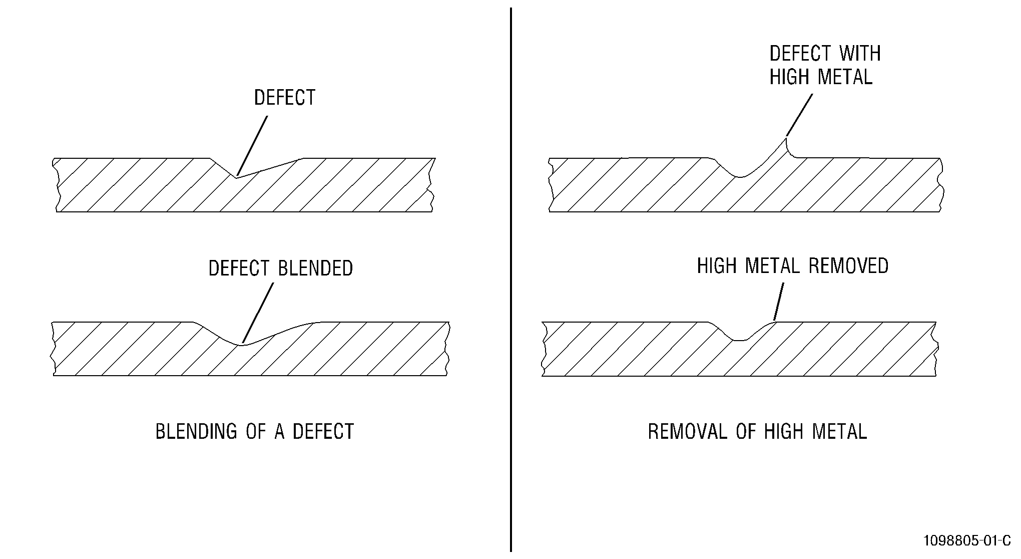
| (1) | High metal is caused by the displacement of metal above a surface. It is found around defects like nicks and scratches. Remove high metal as follows: |
| (a) | Use a fine abrasive stone, emery cloth, or crocus cloth to remove high metal. |
| (b) | Remove only the material that is projecting above the original surface contour. Refer to Figure 3. |