| GENX-1B CLEANING,INSPECTION,AND REPAIR MANUAL | Dated: 12/12/2019 | |
| CIR 72-31-43 , REPAIR 001 | ||
| HIGH PRESSURE COMPRESSOR ROTOR STAGE 3-4 SPOOL - REPAIR - GENERAL BLEND REPAIR OF THE STAGE 3-4 SPOOL | ||
| GENX-1B CLEANING,INSPECTION,AND REPAIR MANUAL | Dated: 12/12/2019 | |
| CIR 72-31-43 , REPAIR 001 | ||
| HIGH PRESSURE COMPRESSOR ROTOR STAGE 3-4 SPOOL - REPAIR - GENERAL BLEND REPAIR OF THE STAGE 3-4 SPOOL | ||
| * * * FOR ALL |
| TASK 72-31-43-300-802 |
| 1 . | General Blend Repair of the Stage 3-4 Spool. |
| A. | This procedure gives instructions to repair the high pressure compressor rotor stage 3-4 spool (HPC 3-4 spool) by blending. Refer to Figure 901. |
| B. | The following maximum repairable limits apply to this repair: |
| NOTE: |
|
| NOTE: |
|
| (4) | Visual Inspection. |
| (c) | Do an inspection of the flange surfaces for: |
| 1 | Nicks, dents, and scratches on the forward flange forward face: |
| Maximum repairable limit: |
|
| 3 | Nicks, dents, and scratches on the aft flange, forward and aft face, and forward flange aft face: |
| Maximum repairable limit: |
|
| (d) | Do an inspection of the outer diameter surfaces for: |
| 1 | Nicks, dents, and scratches: |
| Maximum repairable limit: |
|
| (f) | Deleted. |
| (g) | Do an inspection of the retainer hooks for: |
| 3 | Fretting or wear of forward retainer hooks: |
| Maximum repairable limit: |
|
| (h) | Do an inspection of the seal teeth for: |
| 4 | Nicks, dents, and scratches of stage 2 seal tip: |
| Maximum repairable limit: |
|
| NOTE: |
|
| NOTE: |
|
| NOTE: |
|
| NOTE: |
|
| NOTE: |
|
| 7 | Nicks, dents, and scratches of stage 3 and stage 4 seal tip: |
| Maximum repairable limit: |
|
| NOTE: |
|
| NOTE: |
|
| NOTE: |
|
| NOTE: |
|
| NOTE: |
|
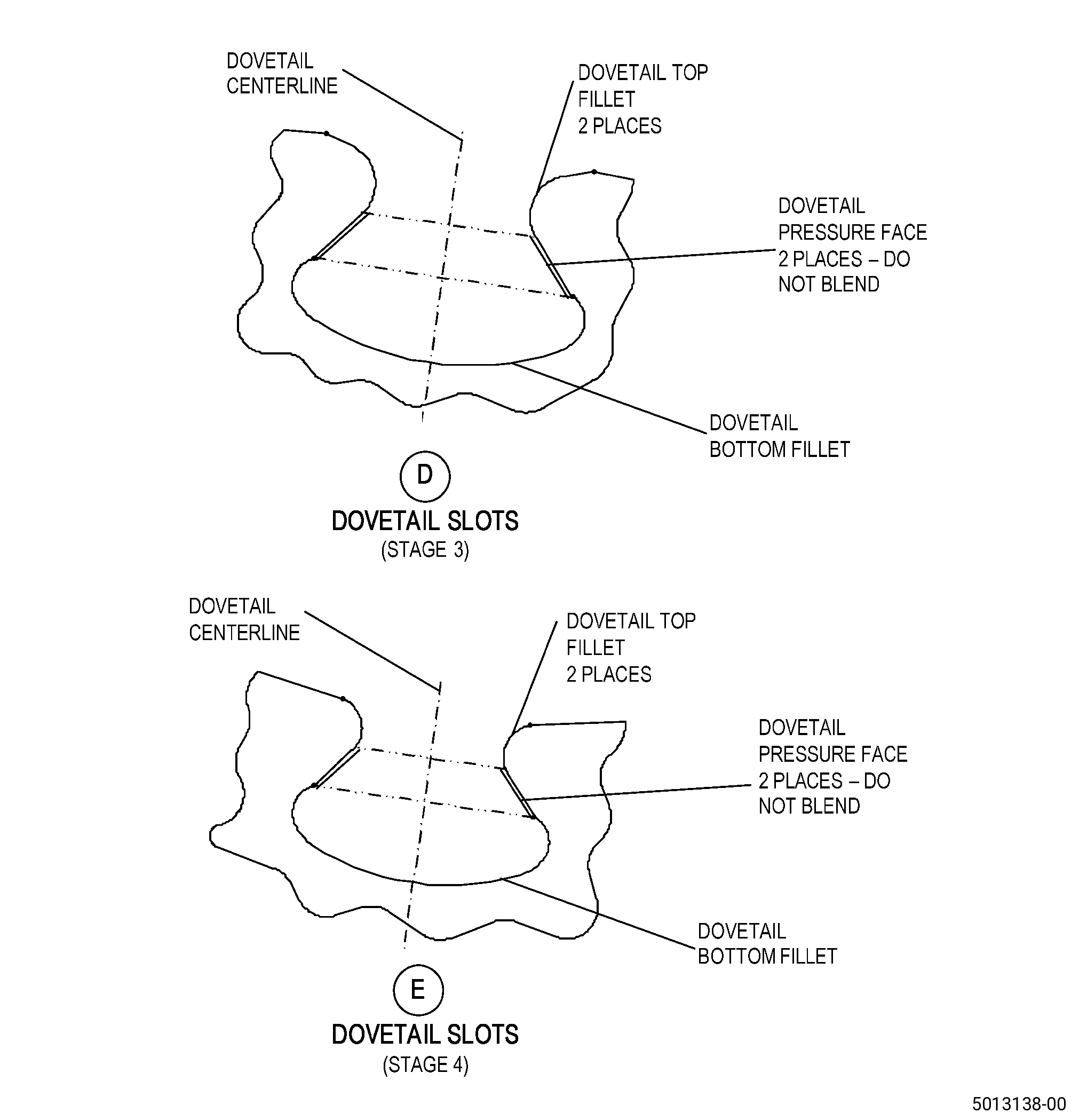
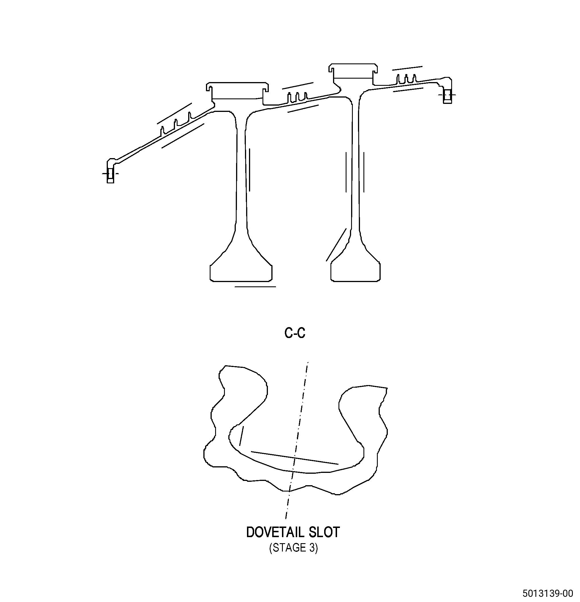
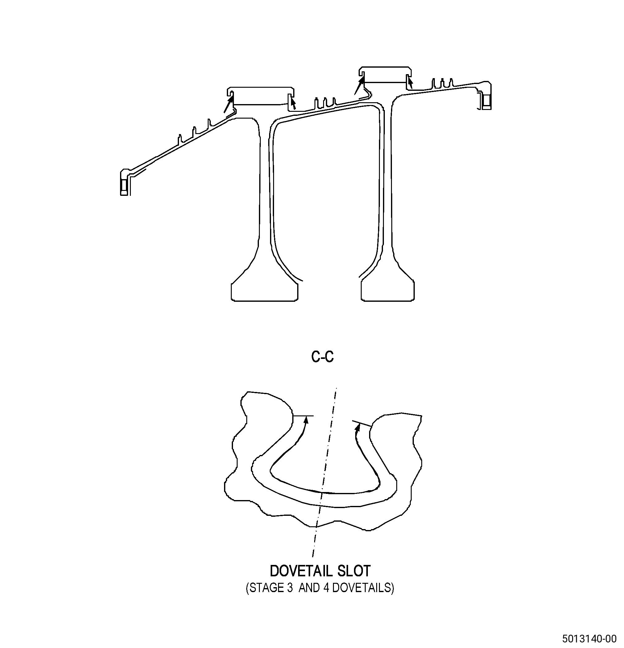
| (i) | Do an inspection of the dovetail for: |
| 3 | Nicks, dents, and scratches on the top fillets: |
| Maximum repairable limit: |
|
| (k) | Do an inspection of diameter E for: |
| 1 | Nicks and scratches: |
| Maximum repairable limit: |
|
| 2 | Dents: |
| Maximum repairable limit: |
|
| (l) | Do an inspection of diameter F for: |
| 1 | Nicks and scratches: |
| Maximum repairable limit: |
|
| 2 | Dents: |
| Maximum repairable limit: |
|
| (m) | Do an inspection of the web-rim fillets: |
| 1 | Nicks, dents, and scratches on stage 3 forward and stage 4 aft/forward web-rim fillets: |
| Maximum repairable limit: |
|
| 2 | Nicks, dents, and scratches on stage 3 aft web-rim fillet: |
| Maximum repairable limit: |
|
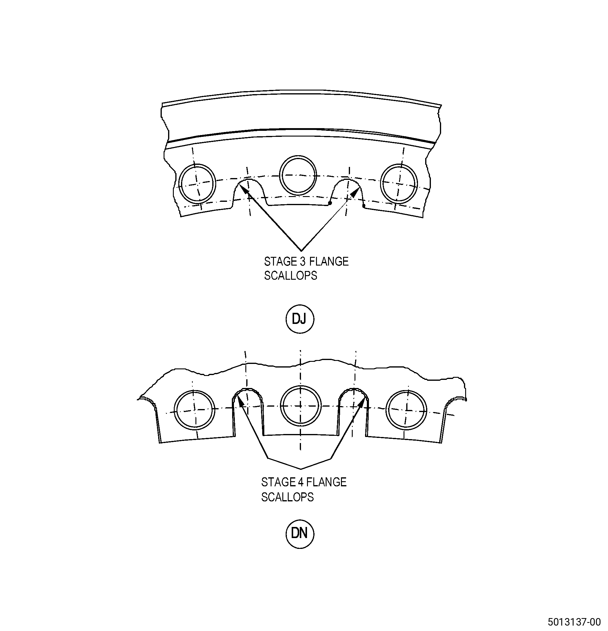
| (n) | Do an inspection of flange scallops: |
| 1 | Nicks, dents, and scratches on stage 3 flange scallop: |
| Maximum repairable limit: |
|
| 2 | Nicks, dents, and scratches on stage 4 flange scallop: |
| Maximum repairable limit: |
|
| (p) | Do an inspection of the disk bores and bore faces for: |
| 1 | Nicks and dents: |
| Maximum repairable limit: |
|
| 2 | Scratches: |
| Maximum repairable limit: |
|
| (q) | Do an inspection of all other surfaces for: |
| 1 | Nicks and dents: |
| Maximum repairable limit: |
|
| 2 | Scratches: |
| Maximum repairable limit: |
|
| C. | The subsequent table gives a list of the part numbers that are applicable to this repair. All part numbers are applicable to all paragraphs unless specified differently. |
|
|||||||||||||||||||||||
| D. | Proprietary/Complex Process Statement. |
| (1) | None. |
| 2 . | Tools, Equipment, and Materials. |
| NOTE: |
|
| A. | Tools and Equipment. |
| (1) | Special Tools. None. |
| (2) | Standard Tools and Equipment. None. |
| (3) | Locally Manufactured Tools. None. |
| B. | Consumable Materials. |
|
| C. | Referenced Procedures. |
| D. | Expendable Parts. None. |
| E. | SPD Information. |
| (1) | Locally Manufactured SPD. None. |
| F. | Special Solutions. None. |
| G. | Test Specimens. None. |
| 3 . | Dimensional Information. |
| Subtask 72-31-43-220-052 |
| A. | Refer to Figure 901 for specified dimensions and locations. |
| NOTE: |
|
| NOTE: |
|
| 4 . | Setup Information. |
| None. |
| 5 . | Procedure. |
| Subtask 72-31-43-350-009 |
| A. | Blend the HPC 3-4 spool. Refer to TASK 70-42-00-350-002 (BLENDING AND REMOVAL OF HIGH METAL PROCEDURES), paragraph 1.B., Figure 901, and as follows: |
| (1) | Remove the minimum quantity of material until it agrees with the maximum blend limits. |
| Subtask 72-31-43-160-006 |
| B. | Clean the repair areas of the HPC 3-4 spool. Refer to TASK 70-21-00-110-051 (CHEMICAL CLEANING) and TASK 70-21-03-160-001 (CLEANING METHOD NO. 3 - STEAM CLEANING). |
| Subtask 72-31-43-110-007 |
| C. | Etch the repair areas of the HPC 3-4 spool. Refer to TASK 70-24-00-110-033 (ETCHING PROCEDURES FOR FLUORESCENT-PENETRANT INSPECTION), TASK 70-24-01-110-034 (SWAB ETCHING PROCEDURE), and as follows: |
| (1) | Use Class B etchant. |
| Subtask 72-31-43-230-002 |
| D. | Alternative Procedure Available. Do an inspection of the repair areas of the HPC 3-4 spool. Refer to TASK 70-32-00-200-002 (INDIRECT INSPECTION METHODS), TASK 70-32-02-230-001 (FLUORESCENT PENETRANT INSPECTION), and as follows: |
| (1) | Use Class G penetrant. |
| (2) | Indications more than 0.015 inch (0.38 mm) are not permitted. |
| (3) | Linear indications are not permitted. |
| NOTE: |
|
| Subtask 72-31-43-230-003 |
| D.A. | Alternative Procedure. Do an inspection of the repair areas of the HPC 3-4 spool. Refer to TASK 70-32-00-200-002 (INDIRECT INSPECTION METHODS), TASK 70-32-03-230-002 (SPOT-FLUORESCENT-PENETRANT INSPECTION), and as follows: |
| (1) | Use Class G penetrant. |
| (2) | Indications more than 0.015 inch (0.38 mm) are not permitted. |
| (3) | Linear indications are not permitted. |
| NOTE: |
|
| Subtask 72-31-43-140-002 |
| WARNING: |
|
| E. | Polish the HPC 3-4 spool repair area to remove the effects of the swab etching procedure as follows: |
| (1) | Use C10-010 abrasive cloth. |
| Subtask 72-31-43-380-002 |
| F. | Peen the repair areas of the HPC 3-4 spool. Refer to TASK 70-47-01-380-016 (SHOTPEENING), Figure 902, Figure 903, and as follows: |
| (1) | Use C04-166 CCW14 shot. |
| (2) | Use C10-205 type N Almen strips. |
| (3) | Peen the HPC 3-4 spool to an intensity of 0.006N-0.012N. |
| (4) | Intensity verification is necessary at all repaired locations. |
| (5) | Coverage must be a minimum of 100 percent. |
| (6) | Ricochet peening is permitted in areas identified in Figure 903. |
| Subtask 72-31-43-160-007 |
| G. | Clean the repair areas of the HPC 3-4 spool. Refer to TASK 70-21-00-110-051 (CHEMICAL CLEANING) and TASK 70-21-03-160-001 (CLEANING METHOD NO. 3 - STEAM CLEANING). |
| Subtask 72-31-43-220-051 |
| H. | Do a final inspection of the HPC 3-4 spool blended areas. |