| GENX-1B CLEANING,INSPECTION,AND REPAIR MANUAL | Dated: 07/21/2022 | |
| CIR 72-31-43 , REPAIR 004 | ||
| HIGH PRESSURE COMPRESSOR ROTOR STAGE 3-4 SPOOL - REPAIR - DOVETAIL FRETTING WEAR REPAIR | ||
| GENX-1B CLEANING,INSPECTION,AND REPAIR MANUAL | Dated: 07/21/2022 | |
| CIR 72-31-43 , REPAIR 004 | ||
| HIGH PRESSURE COMPRESSOR ROTOR STAGE 3-4 SPOOL - REPAIR - DOVETAIL FRETTING WEAR REPAIR | ||
| * * * FOR ALL |
| TASK 72-31-43-300-804 |
| 1 . | Dovetail Fretting Wear Repair. |
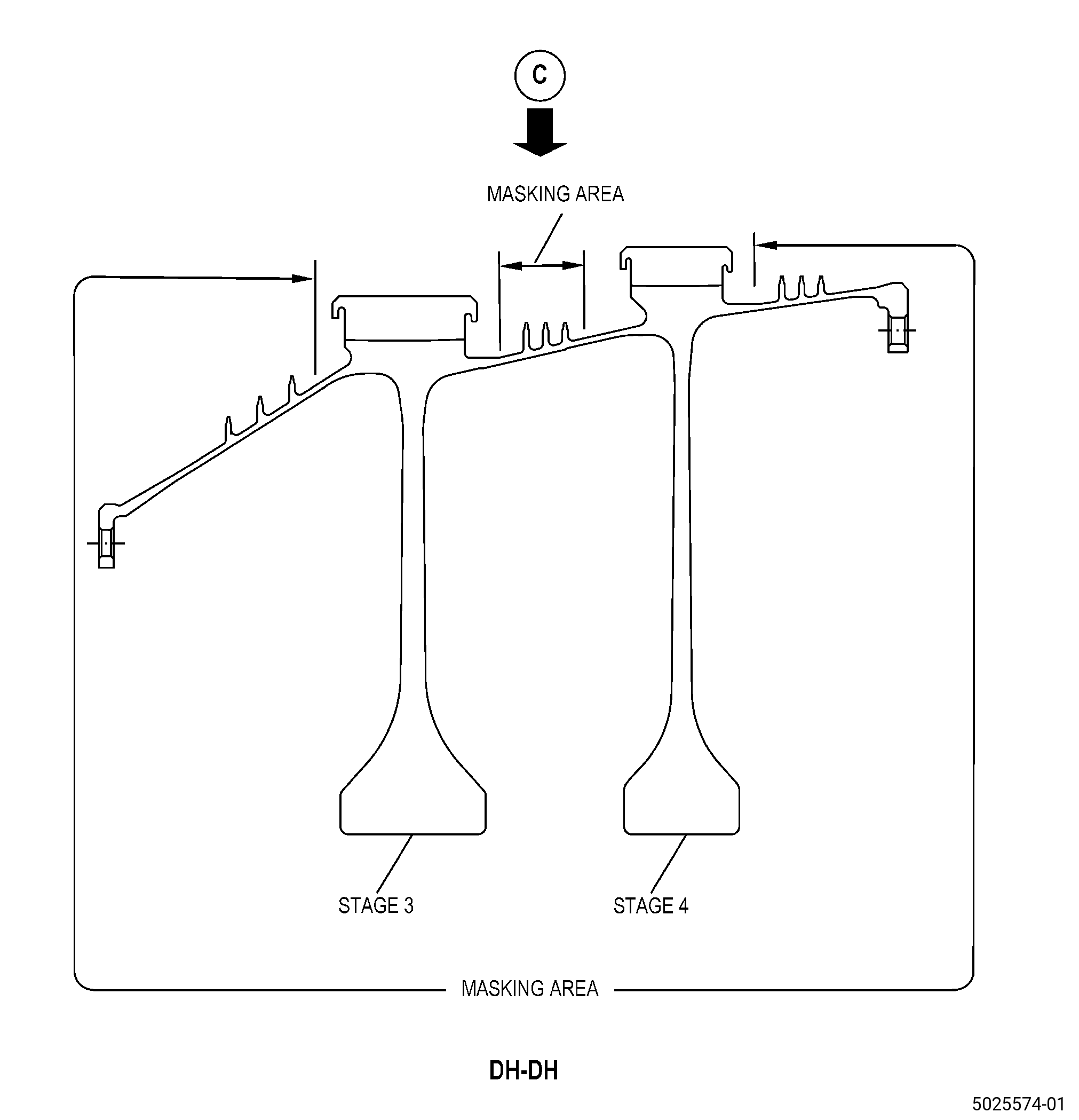
| A. | This procedure gives instructions to repair the HPC rotor stage 3-4 spool (spool) by shotpeening the dovetail pressure faces to remove fretting wear. Refer to Figure 901. |
| B. | The following Maximum Repairable limits apply to this repair: |
| NOTE: |
|
| (4) | Visual Inspection. |
| (i) | Do an inspection of the dovetail for: |
| 5 | Constant fretting wear on the pressure faces of stages 3-4. |
| Maximum repairable limits: |
|
| C. | The subsequent table gives a list of the part numbers that are applicable to this repair. All part numbers are applicable to all paragraphs unless specified differently. |
|
|||||||||||||||||||||||
| D. | Proprietary/Complex Process Statement. |
| (1) | None. |
| 2 . | Tools, Equipment, and Materials. |
| NOTE: |
|
| A. | Tools and Equipment. |
| (1) | Special Tools. None. |
| (2) | Standard Tools and Equipment. None. |
| (3) | Locally Manufactured Tools. None. |
| B. | Consumable Materials. |
|
| C. | Referenced Procedures. |
| D. | Expendable Parts. None. |
| E. | SPD Information. |
| (1) | Locally Manufactured SPD. None. |
| F. | Special Solutions. None. |
| G. | Test Specimens. None. |
| 3 . | Dimensional Information. |
| Subtask 72-31-43-220-075 |
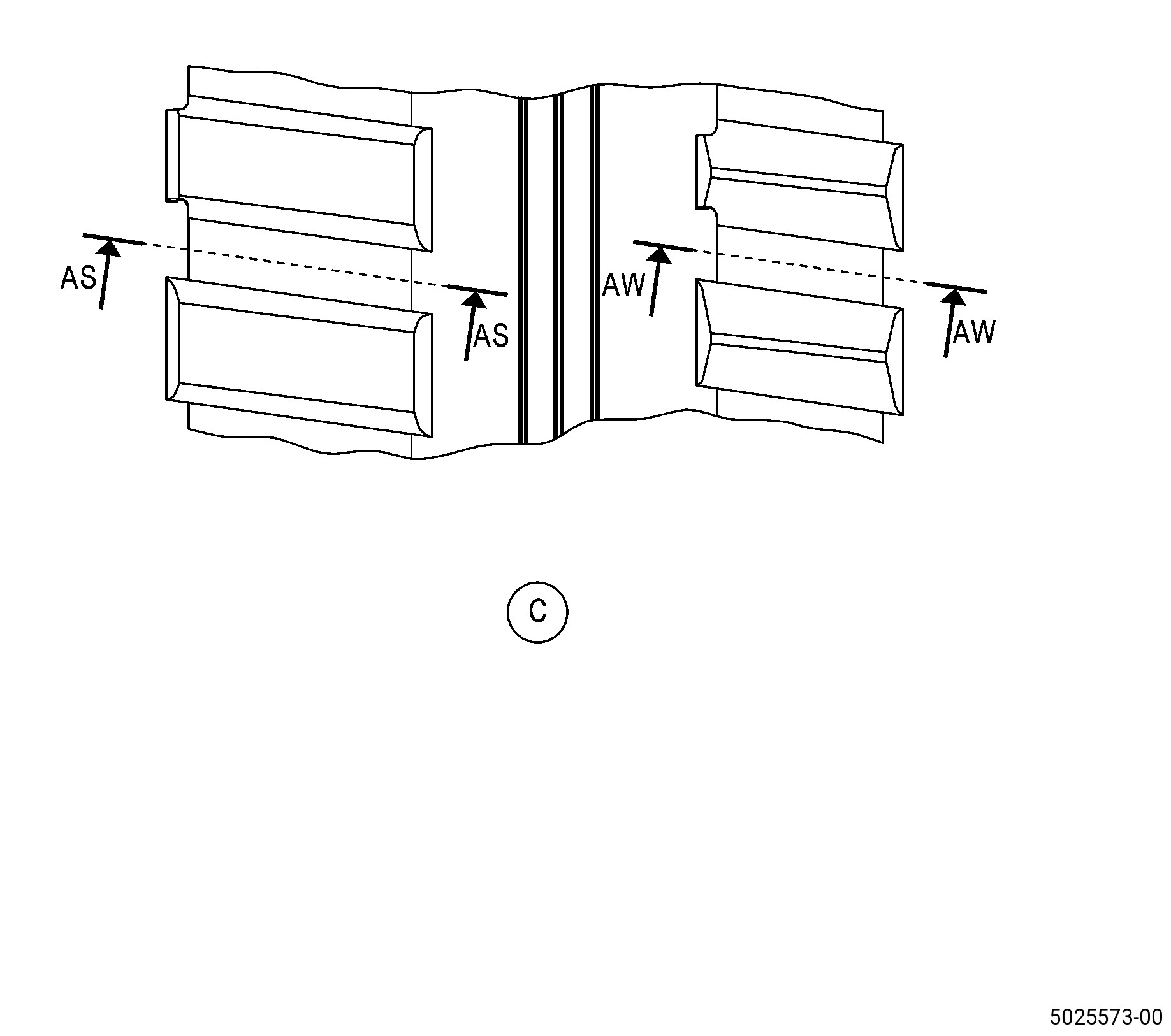
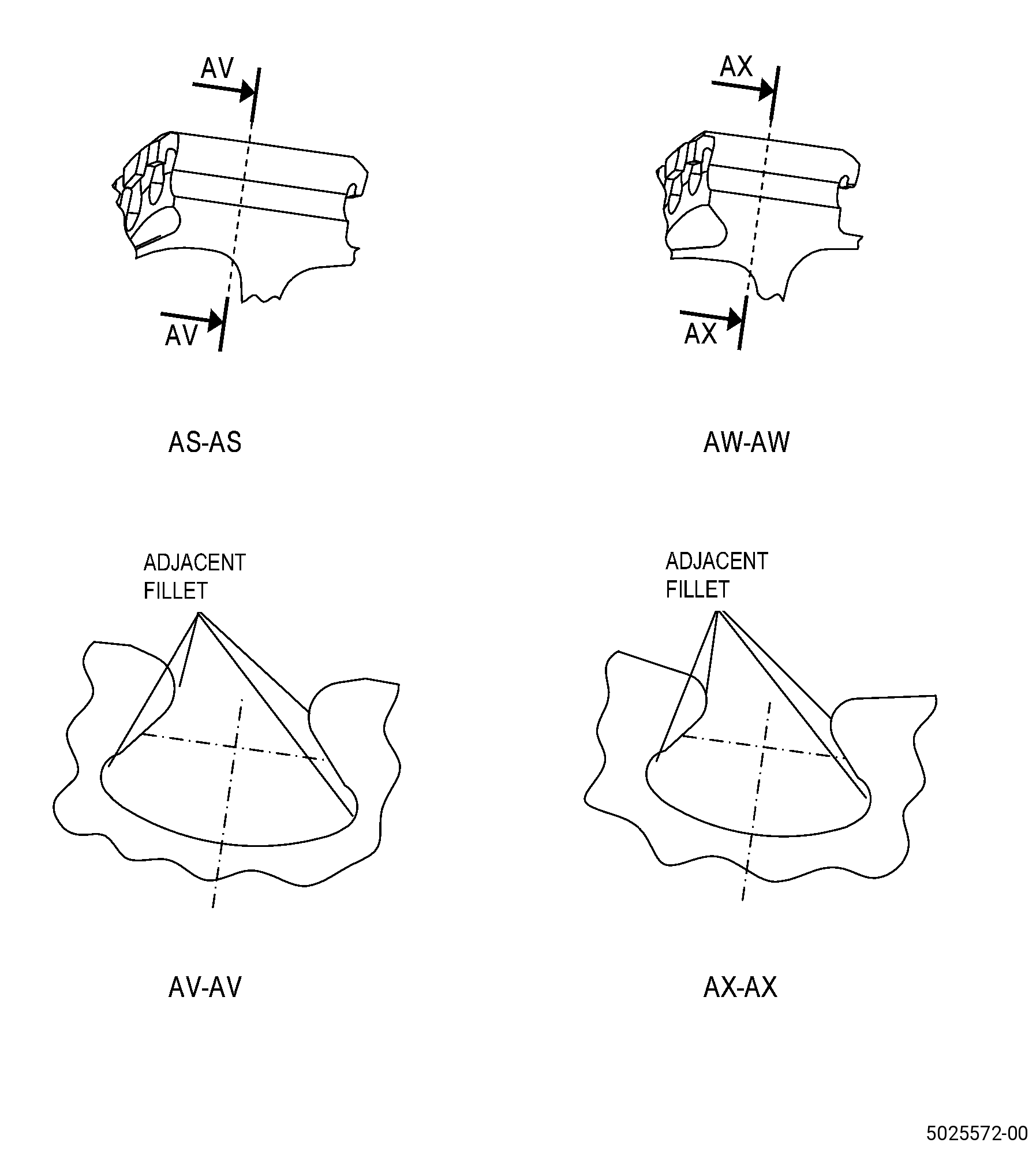
| A. | Refer to Figure 901 for specified dimensions and locations. |
| NOTE: |
|
| NOTE: |
|
| 4 . | Setup Information. |
| None. |
| Subtask 72-31-43-350-021 |
| A. | Deleted. |
| 5 . | Procedure. |
| Subtask 72-31-43-160-010 |
| A. | Clean the dovetail damaged area of the spool. Refer to TASK 72-31-43-100-801 (72-31-43, CLEANING 001). |
| Subtask 72-31-43-110-012 |
| B. | Etch the dovetail damaged areas of the spool. Refer to TASK 70-24-00-110-033 (ETCHING PROCEDURES FOR FLUORESCENT-PENETRANT INSPECTION), TASK 70-24-01-110-034 (SWAB ETCHING PROCEDURE), and as follows: |
| (1) | Use Class B etchant |
| Subtask 72-31-43-230-006 |
| C. | Do an inspection of the dovetail damaged area of the spool. Refer to TASK 70-32-00-200-002 (INDIRECT INSPECTION METHODS), TASK 70-32-03-230-002 (SPOT-FLUORESCENT-PENETRANT INSPECTION), and as follows: |
| (1) | Use Class G penetrant. |
| (2) | For the limits, refer to TASK 72-31-43-200-801 (72-31-43, INSPECTION 001). |
| Subtask 72-31-43-160-011 |
| D. | Clean the spool. Refer to TASK 72-31-43-100-801 (72-31-43, CLEANING 001). |
| Subtask 72-31-43-380-005 |
| E. | Peen the dovetail damaged areas of the spool. Refer to TASK 70-47-01-380-016 (SHOTPEENING), Figure 902, and as follows: |
| Subtask 72-31-43-350-022 |
| (1) | Deleted. |
| Subtask 72-31-43-380-006 |
| (2) | Apply C10-021 plastic tape to the spool areas that you will not peen and to each thermal spray coating area. |
| (3) | UseC04-286 S110 cast steel shot. |
| (4) | Intensity must be 0.006-0.012N. |
| (5) | Do an intensity verification in a scrap part fixture. |
| (6) | Ricochet peening is permitted. |
| (7) | Remove the plastic tape from the spool. |
| Subtask 72-31-43-160-012 |
| F. | If necessary, clean the spool. Refer to TASK 72-31-43-100-801 (72-31-43, CLEANING 001). |