| GENX-1B CLEANING,INSPECTION,AND REPAIR MANUAL | Dated: 04/03/2024 | |
| CIR 72-31-44 , REPAIR 002 | ||
| HIGH PRESSURE COMPRESSOR STAGE 5 BLISK - REPAIR - AIRFOIL BLEND REPAIR | ||
| GENX-1B CLEANING,INSPECTION,AND REPAIR MANUAL | Dated: 04/03/2024 | |
| CIR 72-31-44 , REPAIR 002 | ||
| HIGH PRESSURE COMPRESSOR STAGE 5 BLISK - REPAIR - AIRFOIL BLEND REPAIR | ||
| * * * FOR ALL |
| TASK 72-31-44-300-801 |
| 1 . | Airfoil Blend Repair. |
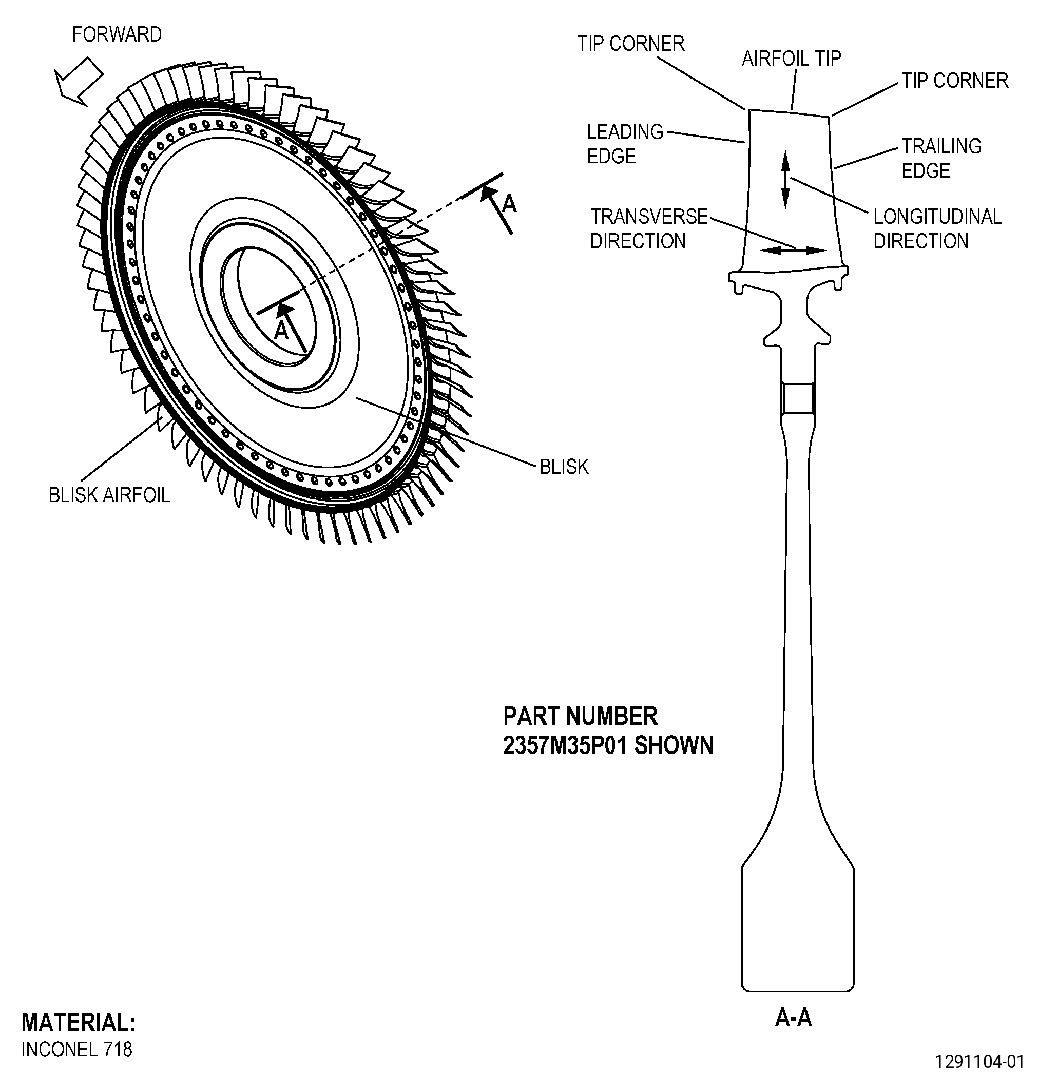
| A. | This procedure gives instructions to repair the high pressure compressor rotor stage 5 blisk (blisk) airfoils by blending the damaged areas. Refer to Figure 901. |
| B. | The following Maximum Repairable limits apply to this repair: |
| NOTE: |
|
| (5) | Visual Inspection. |
| (c) | Do an inspection of area B (leading and trailing edges) on the blisk airfoils for: |
| 1 | Nicks: |
| Maximum repairable limit: |
|
| 2 | Dents and pits: |
| Maximum repairable limit: |
|
| 3 | Scratches and gouges: |
| Maximum repairable limit: |
|
| 4 | Deposits: |
| Maximum repairable limit: |
|
| 5 | Metal splatter deposits: |
| Maximum repairable limit: |
|
| 9 | Tears: |
| Maximum repairable limit: |
|
| (h) | Do an inspection of the tip corners of the blisk airfoils for: |
| 1 | Damage: |
| Maximum repairable limit: |
|
| C. | The subsequent table gives a list of the part numbers that are applicable to this repair. All part numbers are applicable to all paragraphs unless specified differently. |
|
|||||||||||||||||||||||
| D. | Proprietary/Complex Process Statement. |
| (1) | None. |
| 2 . | Tools, Equipment, and Materials. |
| NOTE: |
|
| A. | Tools and Equipment. |
| (1) | Special Tools. None. |
| (2) | Standard Tools and Equipment. |
|
| (3) | Locally Manufactured Tools. None. |
| B. | Consumable Materials. |
| C. | Referenced Procedures. |
|
| D. | Expendable Parts. None. |
| E. | SPD Information. |
| (1) | Spares Supplied. None. |
| (2) | Protected Spares. None. |
| (3) | Locally Manufactured Spares. None. |
| F. | Special Solutions. None. |
| G. | Test Specimens. None. |
| 3 . | Dimensional Information. |
| Subtask 72-31-44-220-052 |
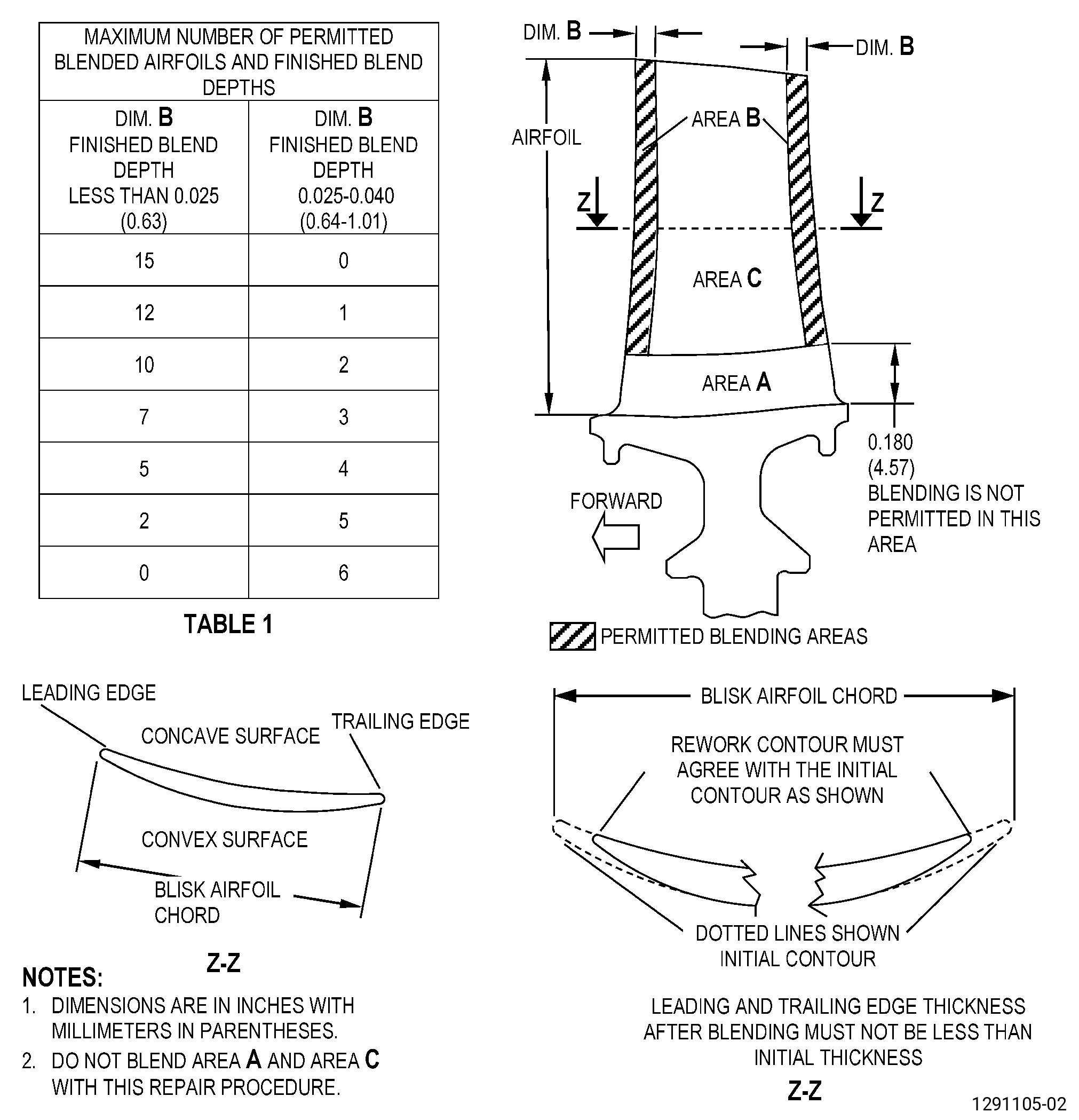
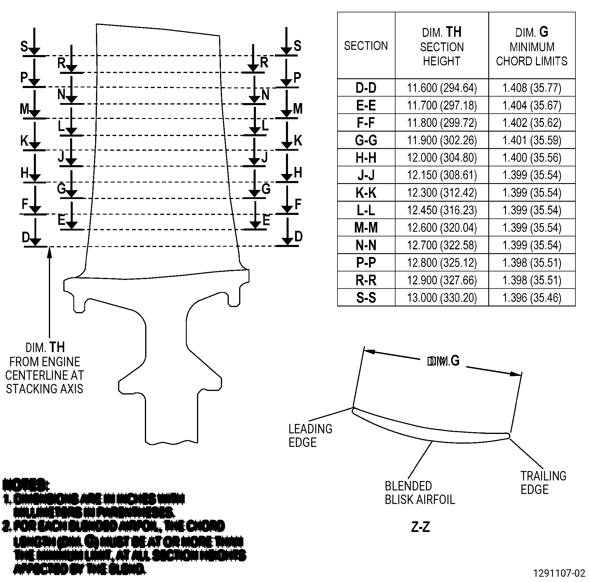
| A. | Refer to Figure 901 and Figure 902 for specified dimensions and locations. |
| NOTE: |
|
| NOTE: |
|
|
| 4 . | Setup Information. |
| None. |
| 5 . | Procedure. |
| Subtask 72-31-44-100-001 |
| CAUTION: |
|
| A. | If necessary, clean the blisk. Refer to TASK 72-31-44-100-801 (72-31-44, CLEANING 001). |
| Subtask 72-31-44-220-079 |
| B. | Do a visual inspection of the blisk airfoils area B (leading and trailing edges) and area A (leading edge). Refer to Figure 901, Figure 902, Figure 904, and as follows: |
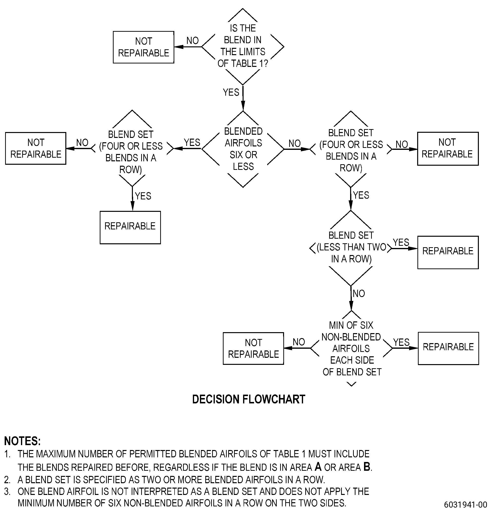
| (1) | The blisk is repairable if it agrees with the conditions that follow: |
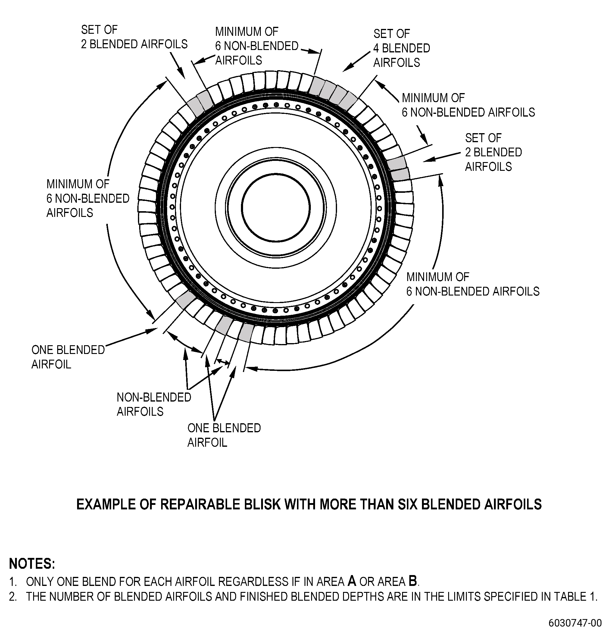
| (a) | A maximum of one blend is permitted for each airfoil, regardless if the blend is in area A or area B. |
| (b) | Refer to Figure 902, Table 1, for the maximum permitted blend depth and the maximum number of airfoils that can be repaired with this repair procedure, and as follows: |
| 1 | The maximum number of permitted blended airfoils of Table 1 must include the blends repaired before, regardless if the blend is in area A or area B. |
| 2 | The total number of blends permitted for each blisk is specified as a combination of the row values of the two columns in Table 1. |
| (c) | You cannot repair the damage in the airfoil area A with this repair procedure. |
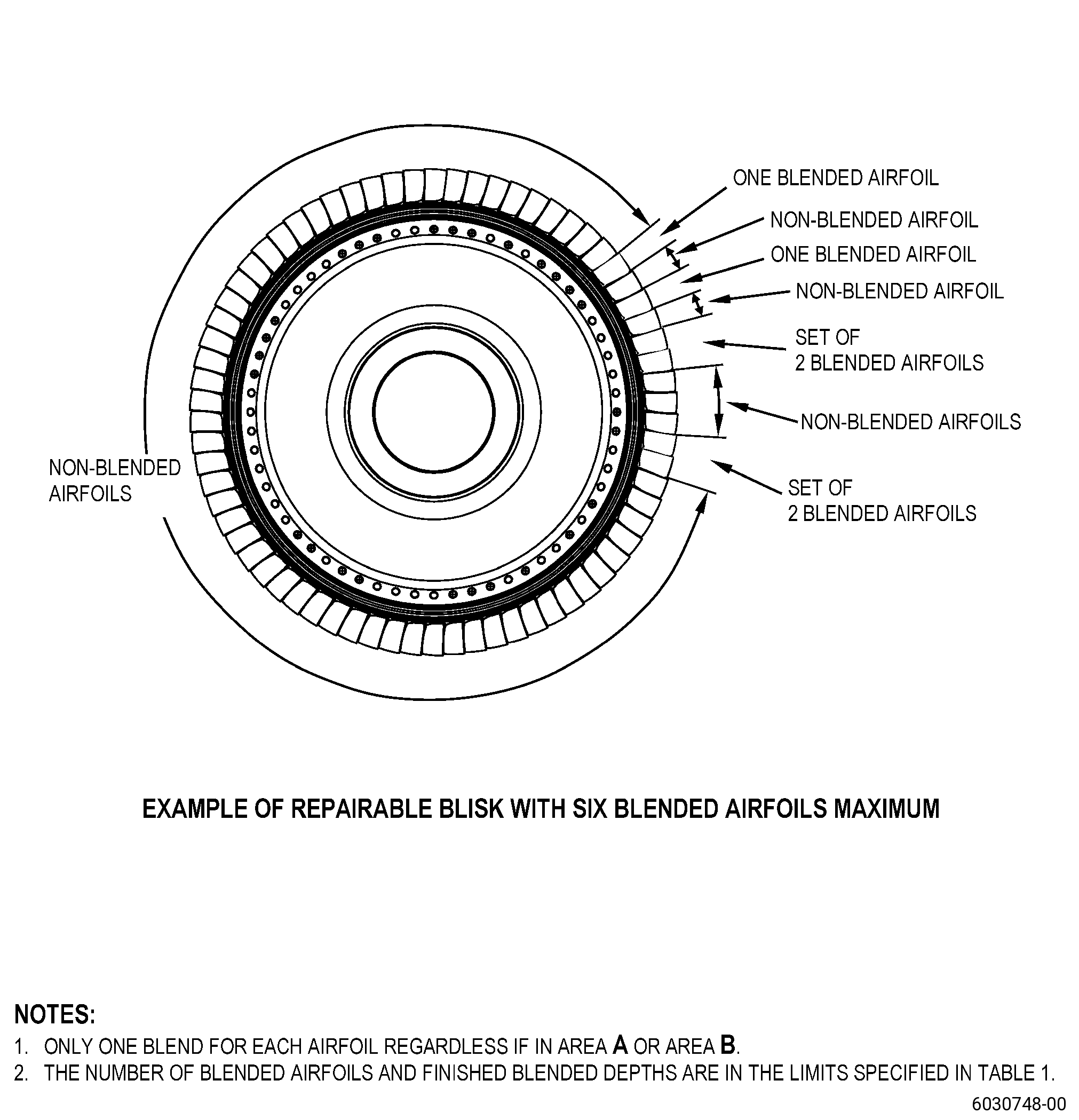
| (d) | A blend set is specified as two or more blended airfoils in a row. |
| (e) | A blend set of four airfoils maximum in a row can be repaired with this repair procedure, and as follows: |
| 1 | For a number of more than six blended airfoils, a minimum of six non-blended airfoils in a row is necessary on the two sides of a set. Refer to Figure 904. |
| 2 | For a number of six blended airfoils maximum, a minimum of six non-blended airfoils in a row is not necessary on the two sides of a set. Refer to Figure 904. |
| (f) | One blend airfoil is not interpreted as a blend set and does not apply the minimum number of six non-blended airfoil in a row on the two sides. |
| Subtask 72-31-44-350-002 |
| WARNING: |
|
| CAUTION: |
|
| CAUTION: |
|
| CAUTION: |
|
| CAUTION: |
|
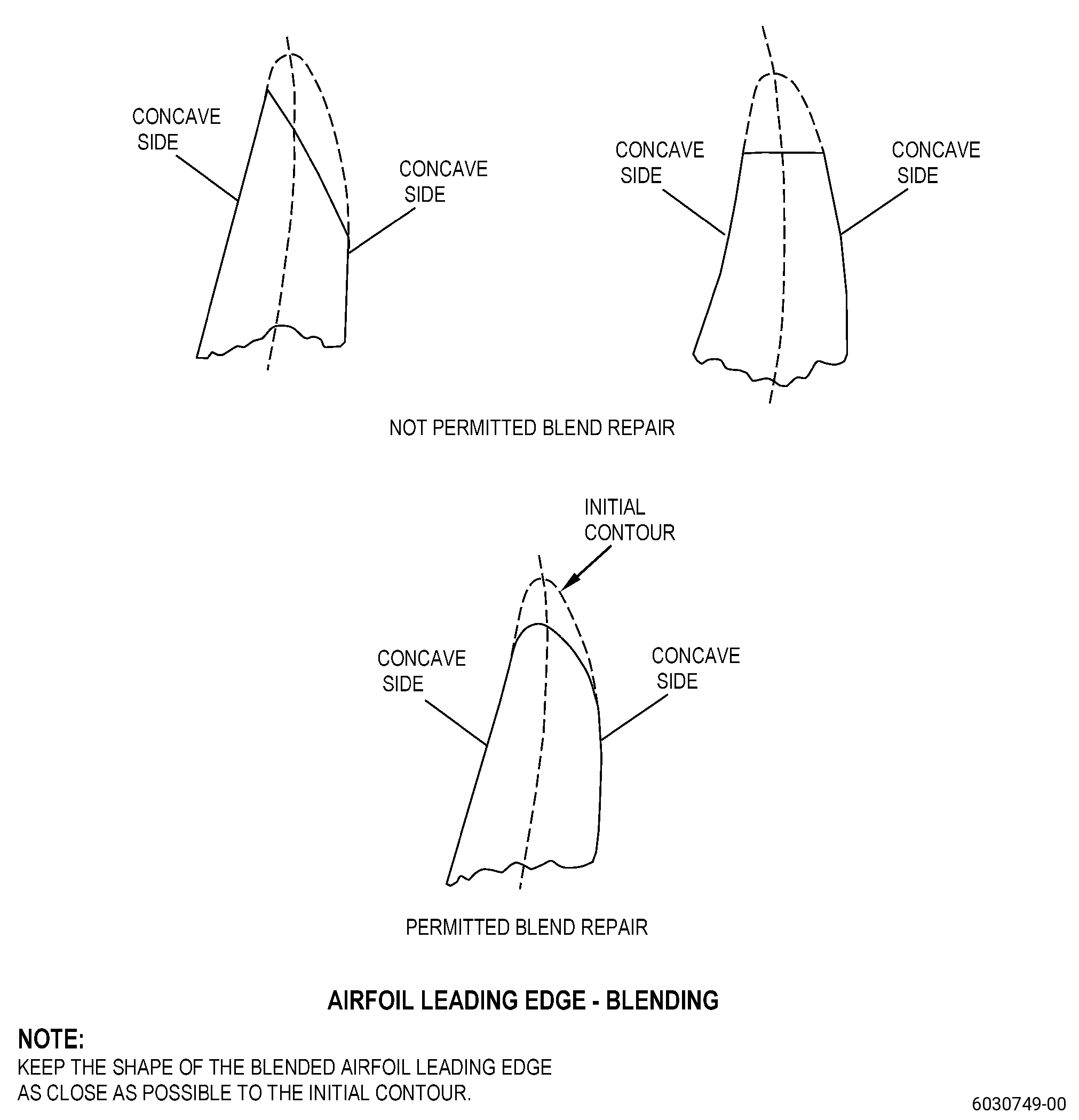
| C. | Blend the damaged area on the blisk airfoil leading and trailing edges, area B. Refer to TASK 70-42-00-350-002 (BLENDING AND REMOVAL OF HIGH METAL PROCEDURES), Figure 902, and as follows: |
| (1) | Make sure that you do not remove the airfoil parent material when you blend to remove the metal splatter or deposits. |
| (2) | You cannot blend area A and area C with this repair procedure. |
| (3) | Use a fine C10-010 abrasive cloth or an abrasive stone as follows: |
| (a) | Blend in longitudinal direction only, parallel to the length of the blisk airfoil. |
| NOTE: |
|
| (b) | Make sure that the surface finish after the blending procedure is equivalent to or better than the initial surface finish. |
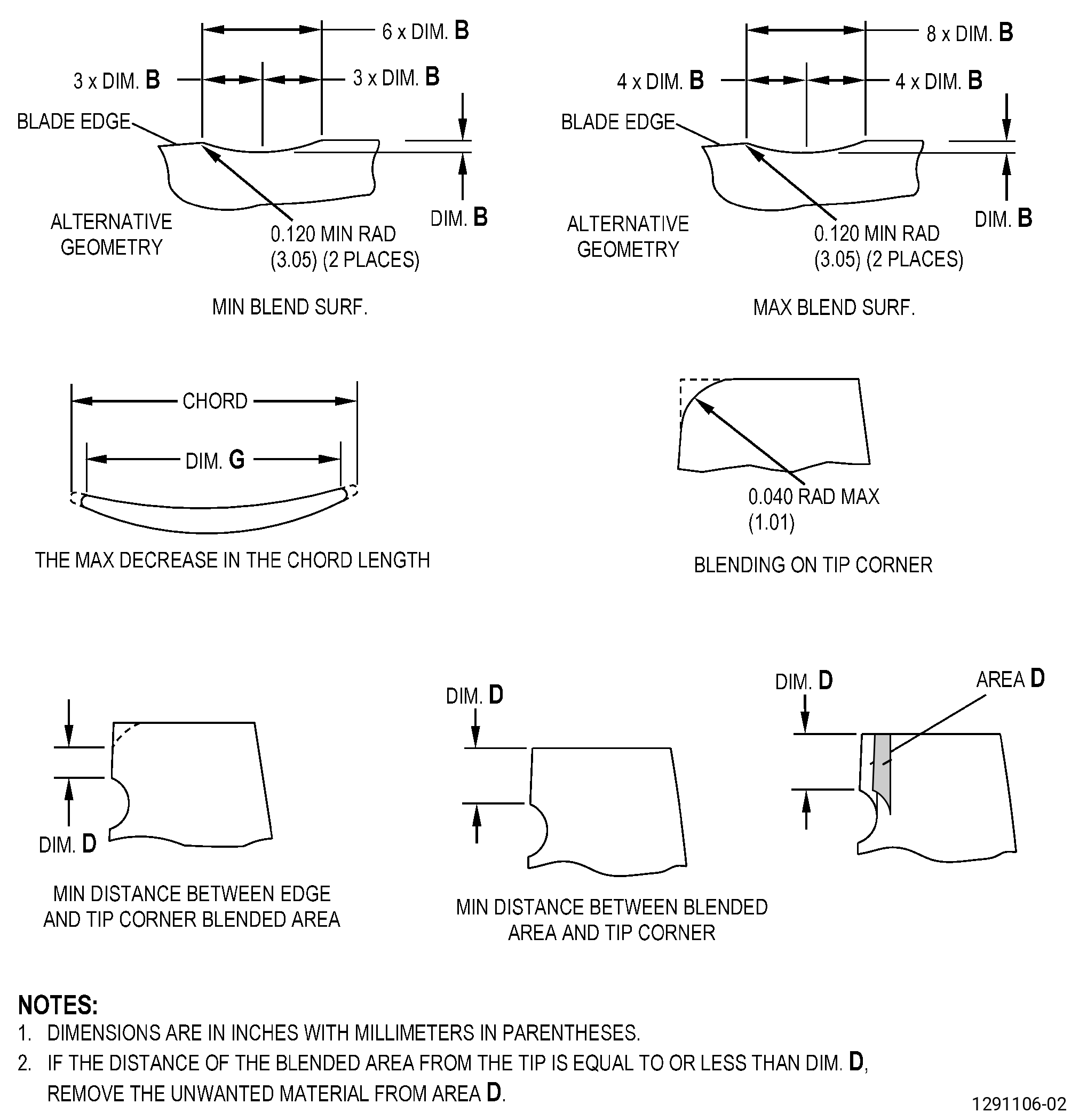
| (4) | For tear damage, blend 1.25 times the damage depth to fully remove the damage. |
| (5) | The blend length must be a minimum of six times the depth of the finished blend, and a maximum of eight times the depth of the finished blend. |
| (6) | The blended contour of the repair area must be the same as the contour of the adjacent non-blended areas. |
| (7) | The leading and trailing edge thickness after blending must not be less than the initial thickness of the adjacent non-blended leading and trailing edge. |
| (8) | The chord length in the repaired section of the blisk airfoil must not be less than the minimum dimension G after the repair. |
| NOTE: |
|
| (9) | If the blend location, measured from the airfoil tip, is equal to or less than dimension D, blend area D as follows: |
| (a) | Remove the unwanted material in area D. |
| (b) | Keep the blend depth to the same depth as the initial blend depth. |
| Subtask 72-31-44-110-008 |
| D. | Etch the blisk airfoil repair area. Refer to TASK 70-24-00-110-033 (ETCHING PROCEDURES FOR FLUORESCENT-PENETRANT INSPECTION), TASK 70-24-01-110-034 (SWAB ETCHING PROCEDURE), and as follows: |
| (1) | Use Class C etchant. |
| Subtask 72-31-44-230-003 |
| E. | Do an inspection of the blisk airfoil repair area. Refer to TASK 70-32-00-200-002 (INDIRECT INSPECTION METHODS), TASK 70-32-02-230-001 (FLUORESCENT PENETRANT INSPECTION), and as follows: |
| (1) | Use Class G penetrant. |
| (2) | Indications are not permitted. |
| Subtask 72-31-44-380-049 |
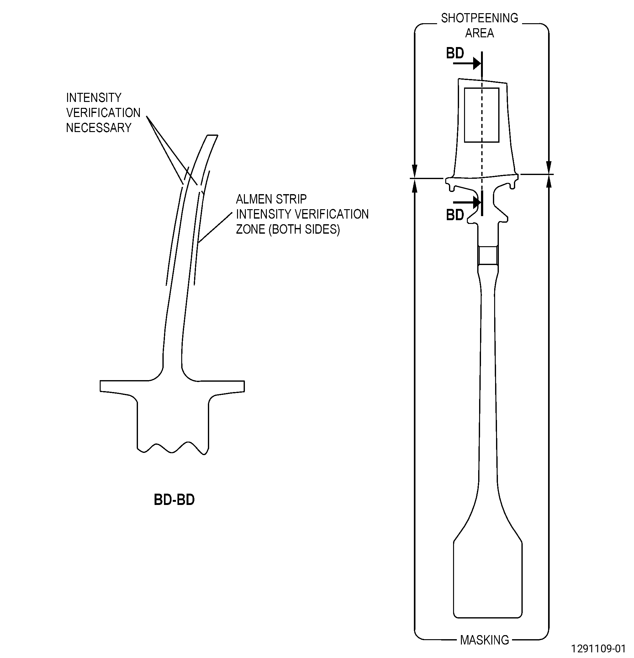
| F. | Peen the blisk airfoil repair area. Refer to TASK 70-47-01-380-016 (SHOTPEENING), Figure 903, and as follows: |
| (1) | Apply C10-021 plastic tape to the blisk areas that you will not peen. |
| (2) | Use C04-286 S110 cast steel shot. |
| (3) | Peen to an intensity of 0.006-0.012N. |
| (4) | The parameters can be set to peen the airfoils to a coverage of 100 percent and the necessary intensity. |
| NOTE: |
|
| NOTE: |
|
| (5) | Intensity verification is necessary in the blisk repaired area. Use a scrap part or simulative fixture. |
| (6) | Overspray is permitted on the concave, convex, leading, and trailing edge areas of the blisk airfoil. |
| (7) | Remove the plastic tape from the blisk. |
| (8) | Remove the plastic tape from the blisk. |
| (9) | Remove the blisk from the holding fixture. |
| Subtask 72-31-44-220-053 |
| G. | Do an inspection of the blisk airfoil surface finish repair area as follows: |
| NOTE: |
|
| (1) | Use a Surtronics 25+ profilometer or equivalent GE approved tool. |
| (2) | Use a 0.010 inch (0.25 mm) cutoff length. |
| (3) | The surface finish of the airfoil must be 32 microinches (0.8 micrometer) or better. |
| WARNING: |
|
| (4) | If necessary, manually polish to do a surface finish improvement of the repaired area and as follows: |
| (a) | Use an C10-010 abrasive cloth or equivalent. |
| Subtask 72-31-44-220-054 |
| H. | Do a final inspection of the blisk airfoil. Refer to TASK 72-31-44-200-801 (72-31-44, INSPECTION 001). |