| GENX-1B CLEANING,INSPECTION,AND REPAIR MANUAL | Dated: 10/31/2017 | |
| CIR 72-31-46 , REPAIR 002 | ||
| HIGH PRESSURE COMPRESSOR CDP SEAL - REPAIR - GENERAL BLEND REPAIR | ||
| GENX-1B CLEANING,INSPECTION,AND REPAIR MANUAL | Dated: 10/31/2017 | |
| CIR 72-31-46 , REPAIR 002 | ||
| HIGH PRESSURE COMPRESSOR CDP SEAL - REPAIR - GENERAL BLEND REPAIR | ||
| * * * FOR ALL |
| TASK 72-31-46-300-802 |
| 1 . | Repair for the CDP Seal: |
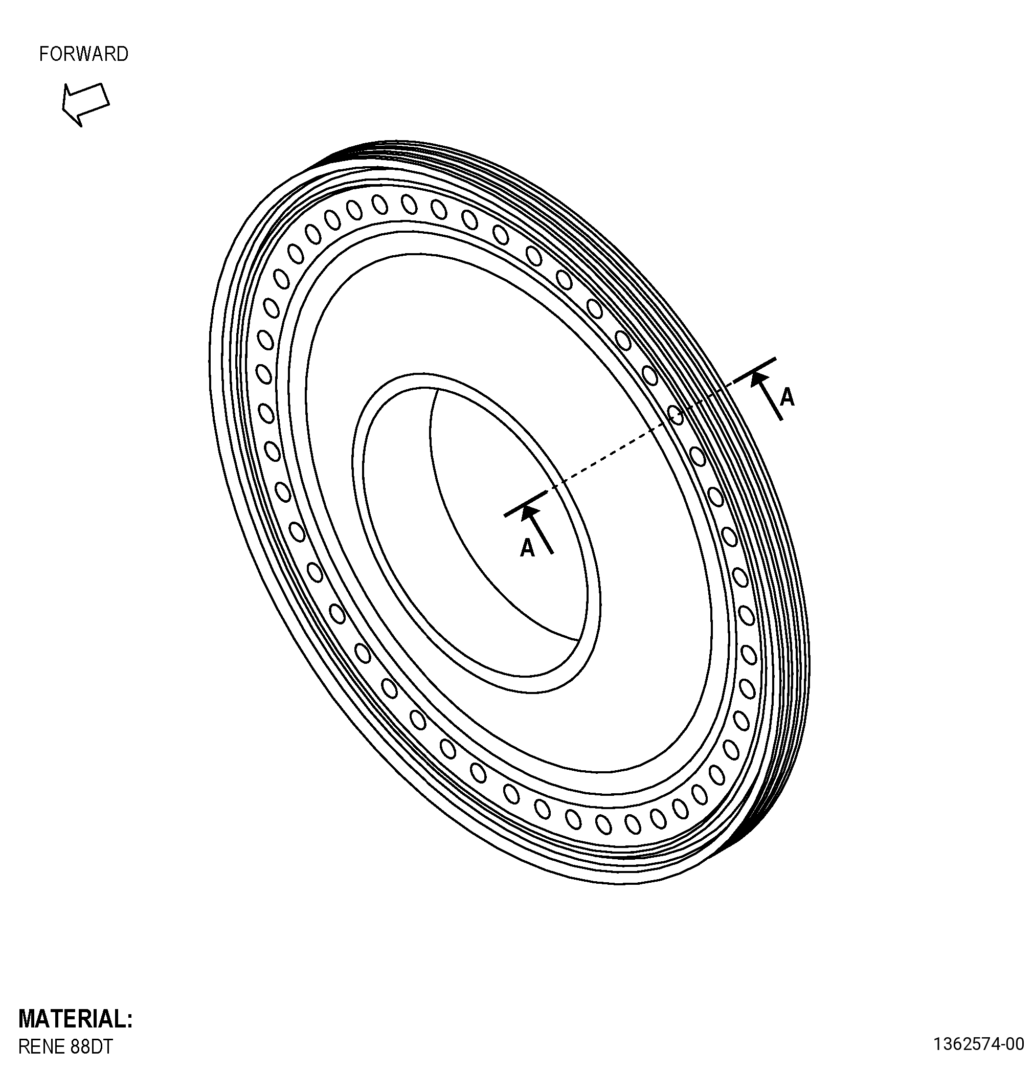
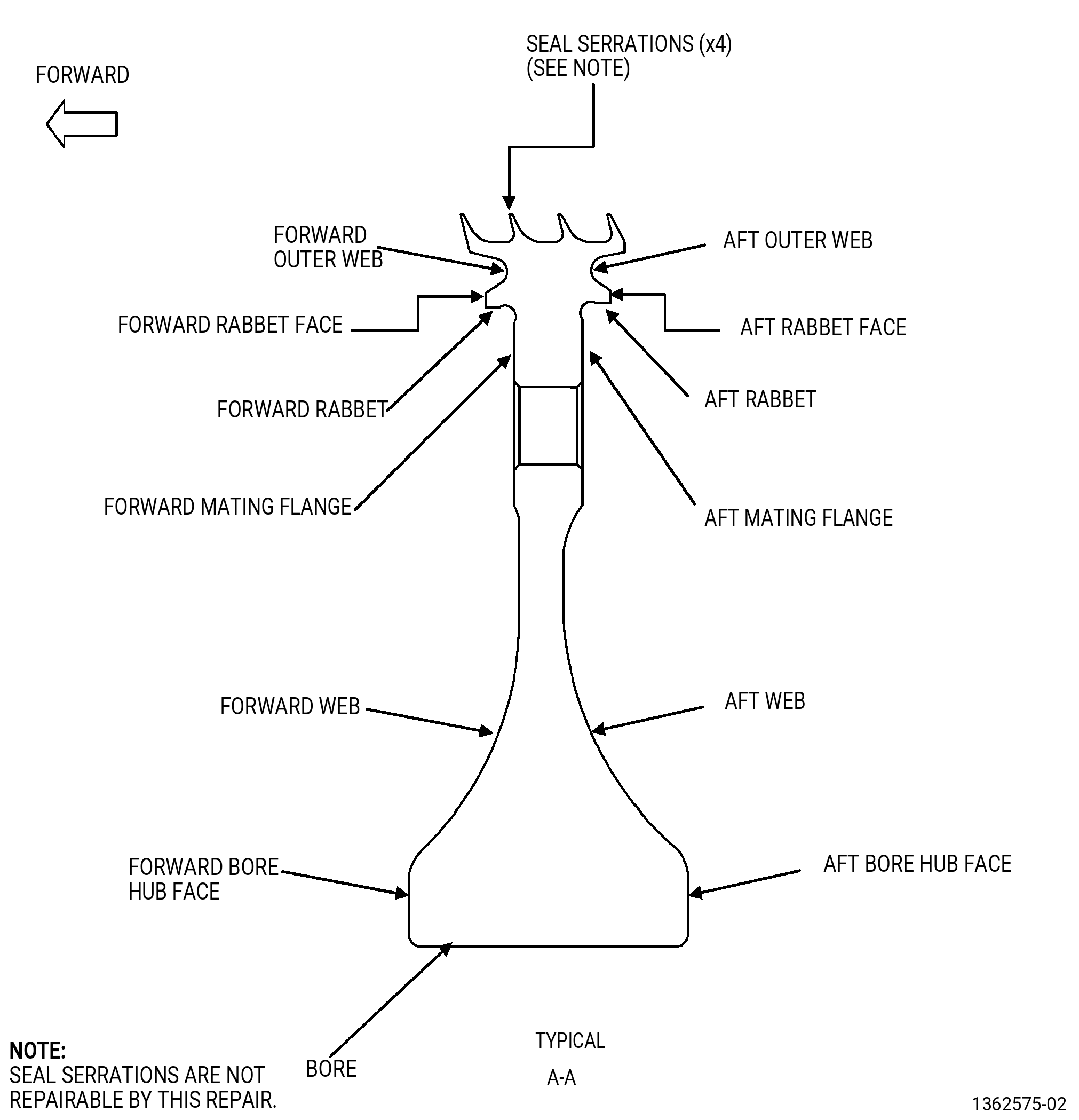
| A. | This procedure gives instructions to repair the following areas of the high pressure compressor discharge pressure rotating seal (CDP seal) by blending. Refer to Figure 901. |
| (1) | Forward and aft outer web area. |
| (2) | Forward and aft mating flanges. |
| (3) | Forward and aft rabbet diameters. |
| (4) | Deleted. |
| (5) | Bore. |
| (6) | All other areas: |
| (a) | Forward and aft web. |
| (b) | Forward and aft bore hub faces. |
| (c) | Between seal serrations. |
| (d) | Forward and aft rabbet faces. |
| B. | The following maximum repairable limits apply to this repair: |
| NOTE: |
|
| NOTE: |
|
| (4) | Visual Inspection. |
| (b) | Do an inspection of the forward and aft outer web area for: |
| 1 | Nicks, dents, tears, or scratches: |
| Maximum repairable limit: |
|
| (c) | Do an inspection of the forward and aft mating flange surfaces for: |
| 1 | Nicks, dents, or scratches: |
| Maximum repairable limit: |
|
| (e) | Do an inspection of the forward rabbet (this does not include the rabbet fillet) for: |
| 1 | Nicks, dents, or scratches: |
| Maximum repairable limit: |
|
| (g) | Do an inspection of the aft rabbet (this does not include the rabbet fillet) for: |
| 1 | Nicks, dents, or scratches: |
| Maximum repairable limit: |
|
| (i) | Do an inspection of the seal serrations for: |
| 1 | Nicks, tears, dents, or bends: |
| Maximum repairable limit: |
|
| (j) | Do an inspection of the bore for: |
| 2 | Marks, nicks, dents and scratches: |
| Maximum repairable limit: |
|
| (k) | Do an inspection of all other areas of the CDP seal not included above for: |
| 1 | Marks, nicks, dents, and scratches: |
| Maximum repairable limit: |
|
| C. | The subsequent table gives a list of the part numbers that are applicable to this repair. All part numbers are applicable to all paragraphs unless specified differently. |
|
|||||||||||||||||||||||
| D. | Proprietary/Complex Process Statement. |
| (1) | None. |
| 2 . | Tools, Equipment, and Materials. |
| NOTE: |
|
| A. | Tools and Equipment. |
| (1) | Special Tools. None. |
| (2) | Standard Tools and Equipment. None. |
| (3) | Locally Manufactured Tools. None. |
| B. | Consumable Materials. |
|
| C. | Referenced Procedures. |
| D. | Expendable Parts. None. |
| E. | SPD Information. None. |
| F. | Special Solutions. None. |
| G. | Test Specimens. None. |
| 3 . | Dimensional Information. |
| Subtask 72-31-46-220-038 |
| A. | Refer to Figure 901 for specified dimensions and locations. |
| NOTE: |
|
| 4 . | Setup Information. |
| None. |
| 5 . | Procedure. |
| Subtask 72-31-46-350-009 |
| A. | If there is coating on the seal teeth, mask the seal teeth. Refer to Figure 901 and as follows: |
| (1) | Use C10-021 plastic tape. |
| Subtask 72-31-46-350-010 |
| B. | Blend the CDP seal. Refer to TASK 70-42-00-350-002 (BLENDING AND REMOVAL OF HIGH METAL PROCEDURES), Figure 901, and as follows: |
| (1) | For the blending limits refer to paragraph 1.B. |
| Subtask 72-31-46-100-003 |
| C. | Clean the repaired areas. Refer to TASK 70-21-00-110-051 (CHEMICAL CLEANING) and TASK 70-21-03-160-001 (CLEANING METHOD 3 - STEAM CLEANING). |
| Subtask 72-31-46-110-017 |
| D. | Etch the repaired areas. Refer to TASK 70-24-00-110-033 (ETCHING PROCEDURES FOR FLUORESCENT-PENETRANT INSPECTION), TASK 70-24-01-110-034 (SWAB ETCHING PROCEDURE), and as follows: |
| (1) | Use Class C or Class G etchant. |
| Subtask 72-31-46-200-001 |
| E. | Alternative Procedure Available. Do an inspection of the repaired areas. Refer to TASK 70-32-00-200-002 (INDIRECT INSPECTION METHODS), TASK 70-32-02-230-001 (FLUORESCENT PENETRANT INSPECTION), and as follows: |
| (1) | Use Class G penetrant. |
| (2) | Indications more than 0.015 inch (0.38 mm) are not permitted. |
| (3) | Linear indications are not permitted. |
| NOTE: |
|
| Subtask 72-31-46-200-002 |
| E.A. | Alternative Procedure. Do an inspection of the repaired areas. Refer to TASK 70-32-00-200-002 (INDIRECT INSPECTION METHODS), TASK 70-32-03-230-002 (SPOT-FLUORESCENT-PENETRANT INSPECTION), and as follows: |
| (1) | Use Class G penetrant. |
| (2) | Indications more than 0.015 inch (0.38 mm) are not permitted. |
| (3) | Linear indications are not permitted. |
| NOTE: |
|
| Subtask 72-31-46-350-011 |
| WARNING: |
|
| F. | Polish the CDP Seal repair area to remove the effects of the swab etching procedure as follows: |
| (1) | Use C10-010 abrasive cloth. |
| Subtask 72-31-46-380-002 |
| G. | Peen the repaired areas. Refer to TASK 70-47-01-380-016 (SHOTPEENING), Figure 901, and as follows: |
| (1) | Use C04-166 CCW14 shot. |
| (2) | Peen to an intensity of 0.006-0.012 N. |
| (3) | Intensity verification is necessary in all peened surfaces. |
| (4) | Coverage must be a minimum of 100 percent. |
| (5) | Overspray is permitted. |
| Subtask 72-31-46-100-004 |
| H. | Clean the repaired areas. Refer to TASK 70-21-00-110-051 (CHEMICAL CLEANING) and TASK 70-21-03-160-001 (CLEANING METHOD 3 - STEAM CLEANING). |
| Subtask 72-31-46-220-039 |
| I. | Do a final inspection of the CDP seal blended areas. |