| GENX-1B CLEANING,INSPECTION,AND REPAIR MANUAL | Dated: 03/02/2020 | |
| CIR 72-32-01 , REPAIR 001 | ||
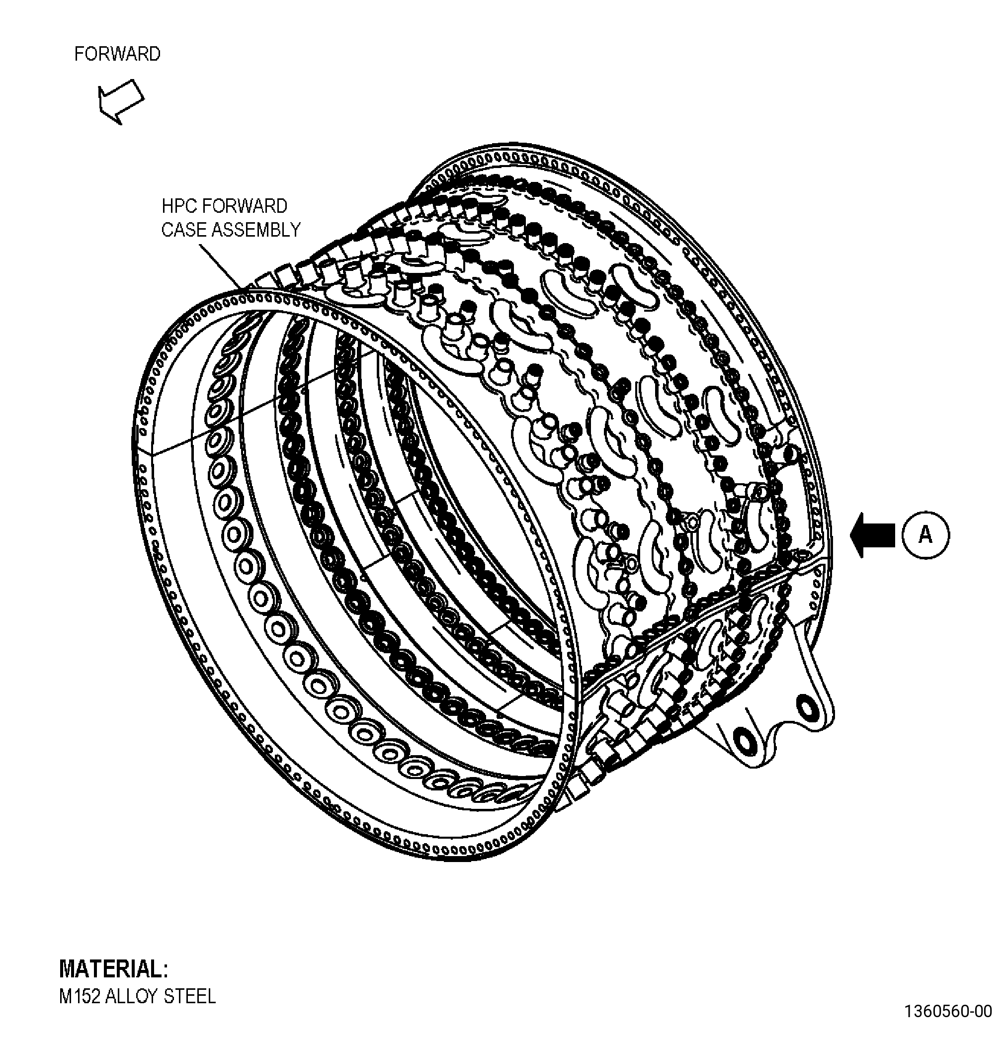
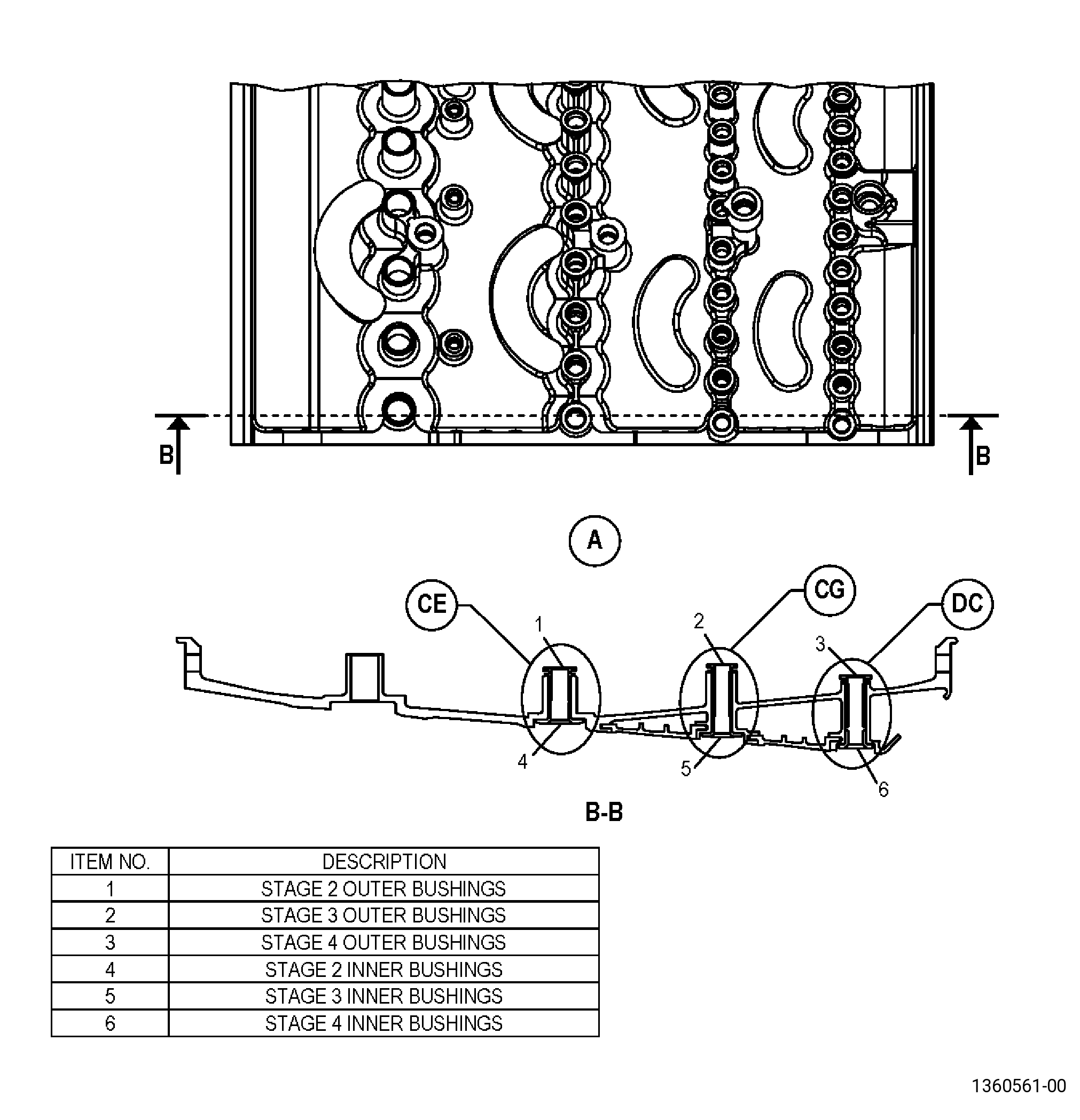
| HIGH PRESSURE COMPRESSOR STATOR ASSEMBLY - HIGH PRESSURE COMPRESSOR STATOR FORWARD CASE ASSEMBLY - REPAIR - REMOVAL AND INSTALLATION OF VSV BUSHINGS | ||
| GENX-1B CLEANING,INSPECTION,AND REPAIR MANUAL | Dated: 03/02/2020 | |
| CIR 72-32-01 , REPAIR 001 | ||
| HIGH PRESSURE COMPRESSOR STATOR ASSEMBLY - HIGH PRESSURE COMPRESSOR STATOR FORWARD CASE ASSEMBLY - REPAIR - REMOVAL AND INSTALLATION OF VSV BUSHINGS | ||
| * * * FOR ALL |
| TASK 72-32-01-300-801 |
| 1 . | Repair for the High Pressure Compressor Stator Forward Case Assembly. |
| A. | This procedure gives instructions to repair the high pressure compressor (HPC) stator forward case assembly by removal and replacement of damage or worn variable stator vane (VSV) bushings. Refer to Figure 901. |
| B. | The following maximum repairable limits apply to this repair: |
| NOTE: |
|
| NOTE: |
|
| (4) | Visual Inspection. |
| (f) | Do an inspection stage 1 VSV bore area and stage 2-4 bushing areas for: |
| 2 | Nicks and scratches on the mating surfaces: |
| Maximum repairable limit: |
|
| 3 | Wear or damage on the ID of the counter bores: |
| Maximum repairable limit: |
|
| 4 | Wear in the bore: |
| Maximum repairable limit: |
|
| (6) | Special Dimensional Inspection: |
| (a) | Do a dimensional inspection as follows: |
| 7 | Stage 2 bushing diameters: |
| Maximum repairable limit: |
|
| 8 | Stage 3 and 4 bushing diameters: |
| Maximum repairable limit: |
|
| C. | The subsequent table gives a list of the part numbers that are applicable to this repair. All part numbers are applicable to all paragraphs unless specified differently. |
|
||||||||||||||||||||||||||||||||||||
| D. | Proprietary/Complex Process Statement. |
| (1) | None. |
| 2 . | Tools, Equipment, and Materials. |
| NOTE: |
|
| A. | Tools and Equipment. |
| (1) | Special Tools. |
|
| (2) | Standard Tools and Equipment. None. |
| (3) | Locally Manufactured Tools. None. |
| B. | Consumable Materials. |
| C. | Referenced Procedures. |
|
| D. | Expendable Parts. None. |
| E. | SPD Information. |
|
| F. | Special Solutions. None. |
| G. | Test Specimens. None. |
| 3 . | Dimensional Information. |
| Subtask 72-32-01-220-054 |
| A. | Refer to Figure 904 for specified dimensions and locations. |
| NOTE: |
|
| NOTE: |
|
| 4 . | Setup Information. |
| None. |
| 5 . | Procedure. |
| Subtask 72-32-01-350-001 |
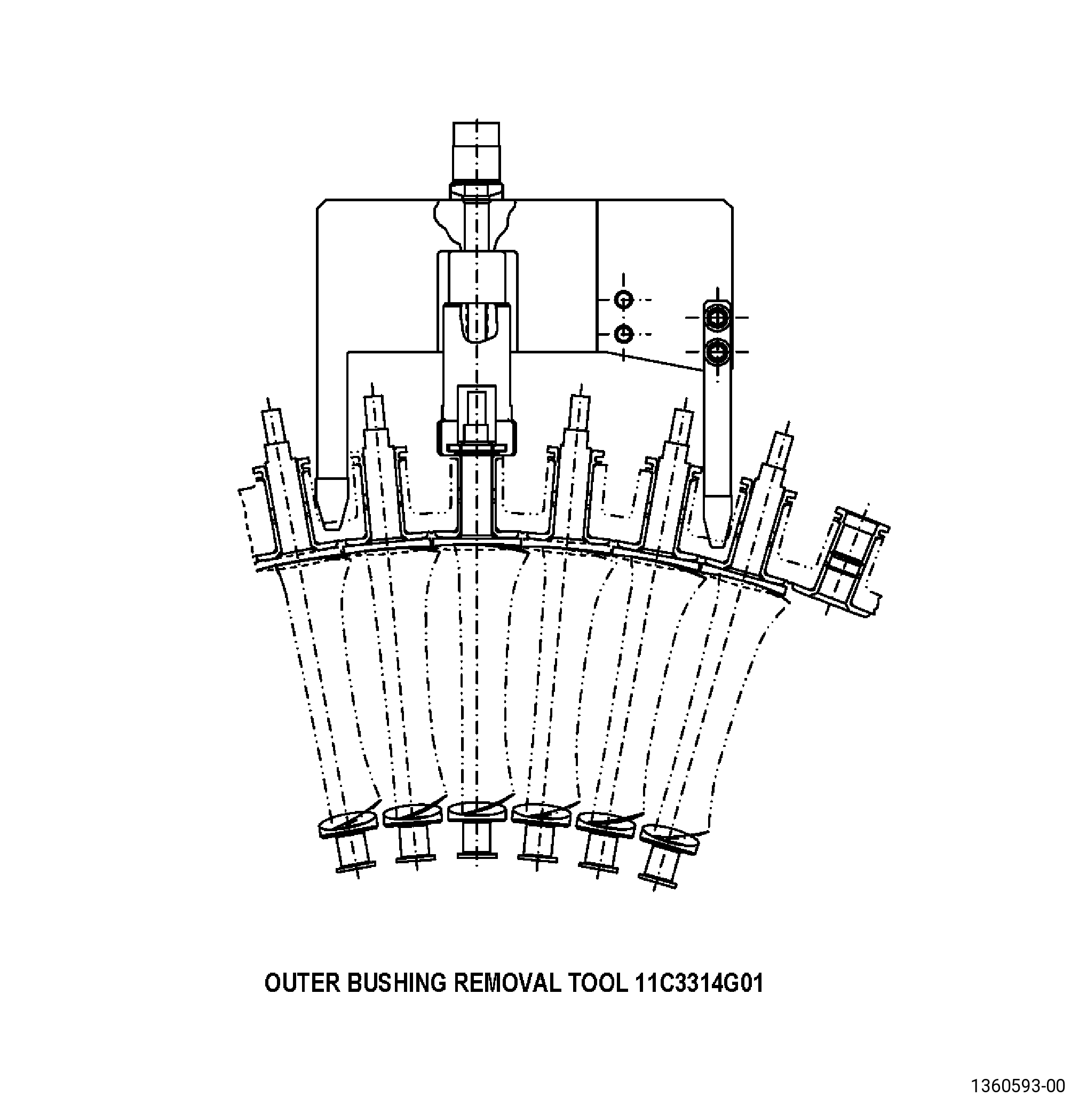
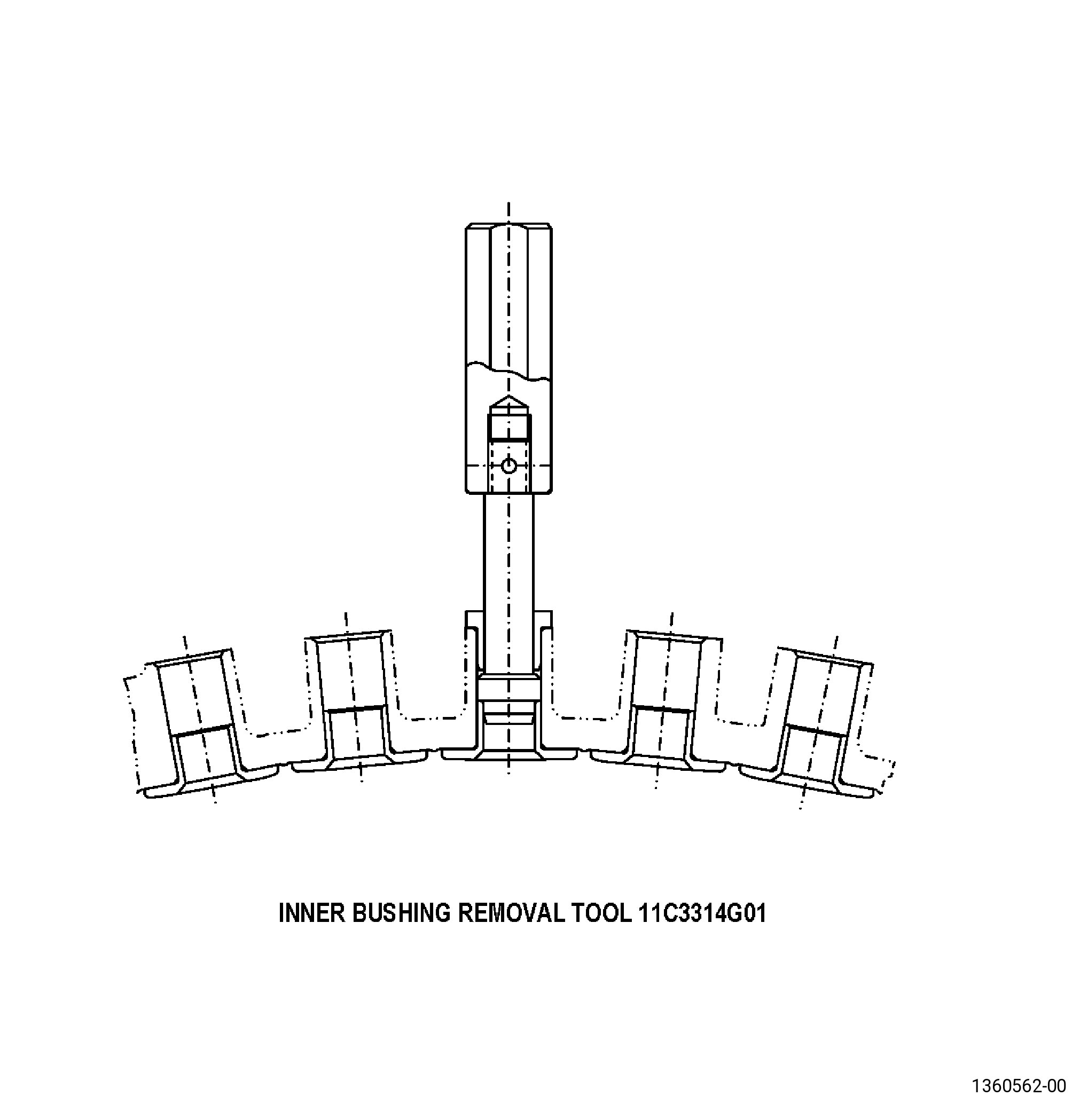
| A. | If necessary, remove the damaged inner and outer bushings from the VSV bores as follows: |
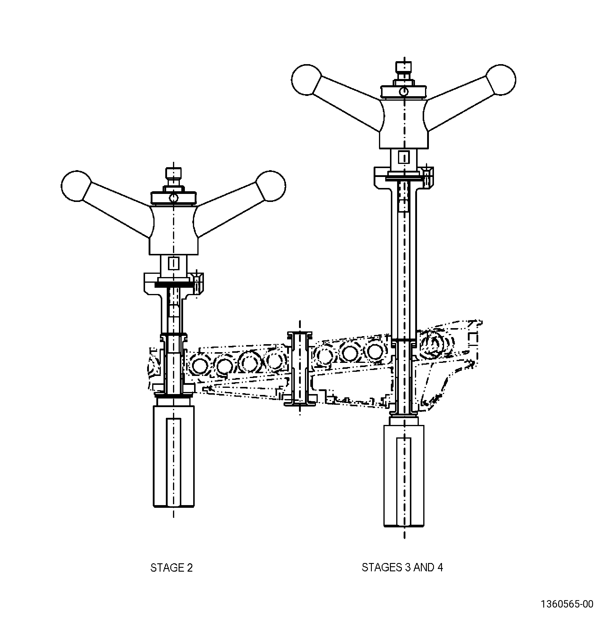
| (1) | Use the 11C3314 bushing puller. Refer to Figure 902. |
| (2) | If non-damaged bushings were removed, check the serviceability of the bushings. Refer to Figure 901, Figure 905, Figure 906, Figure 907, and do as follows: |
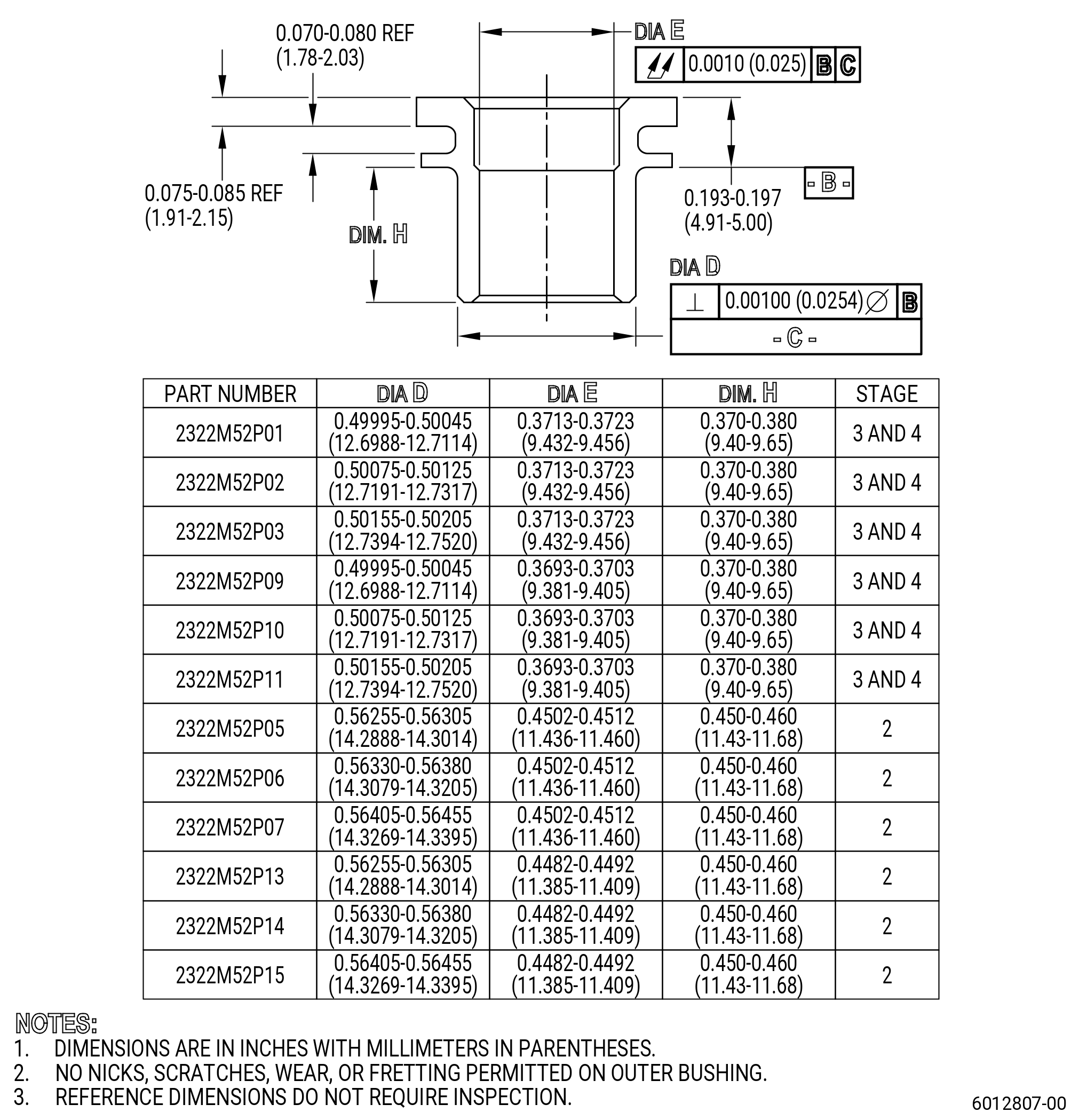
| (a) | Do a dimensional inspection of the bushings as follows: |
| 1 | Make sure that the bushing agrees with the dimensional limits. |
| (b) | Do a visual inspection of the bushings as follows: |
| 1 | Make sure that there is no wear on the bushing. |
| 2 | Make sure that there is no fretting on the bushing. |
| 3 | Make sure that there are no nicks or scratches greater than 0.005 inch (0.13 mm), on more than 20 percent of the area. |
| (c) | If serviceable, put in a bag as follows: |
| 1 | Tag as serviceable. |
| 2 | Record the stage of the bushing. |
| (d) | If not serviceable, discard the bushing. |
| Subtask 72-32-01-110-005 |
| B. | Clean the VSV bores. Refer to TASK 70-21-00-110-051 (CHEMICAL CLEANING), TASK 70-21-23-110-053 (CLEANING METHOD 23 - HAND-WIPE DEGREASING), and as follows: |
| WARNING: |
|
| WARNING: |
|
| (2) | Use a C10-182 cleaning cloth moistened with C04-003 acetone or C04-035 isopropyl alcohol to clean the repair area. |
| (3) | Replace the dirty cloths with clean cloths until the last moist cloth stays clean. |
| Subtask 72-32-01-350-002 |
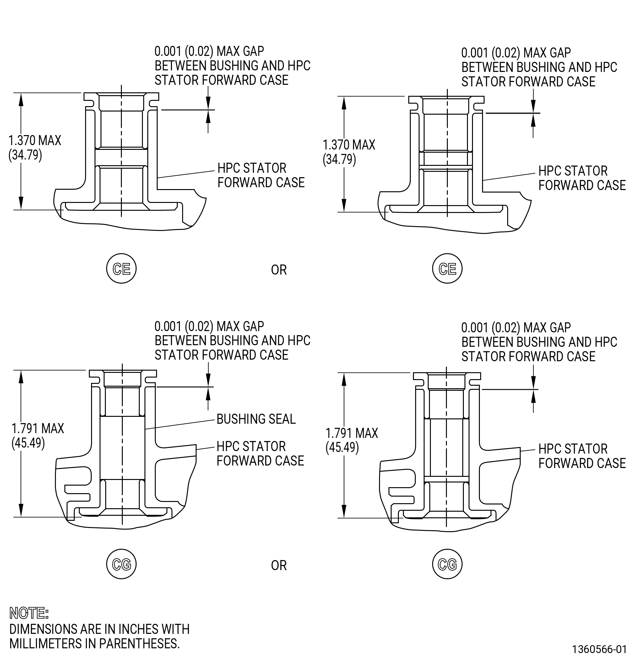
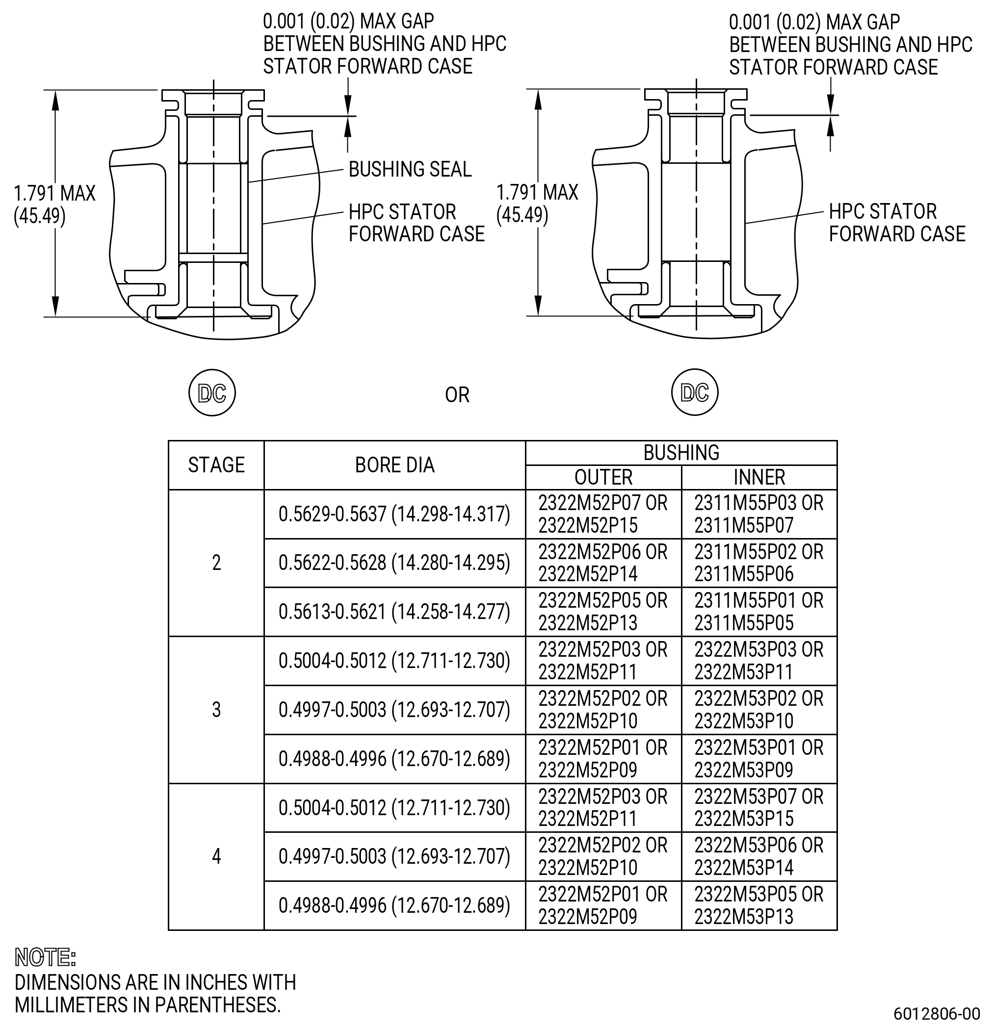
| C. | Install the inner and outer bushings in the VSV bores. Refer to Figure 904 and do as follows: |
| (1) | Measure the VSV bore diameter. |
| (2) | Get the correct bushing for the VSV bore. Refer to Figure 904. |
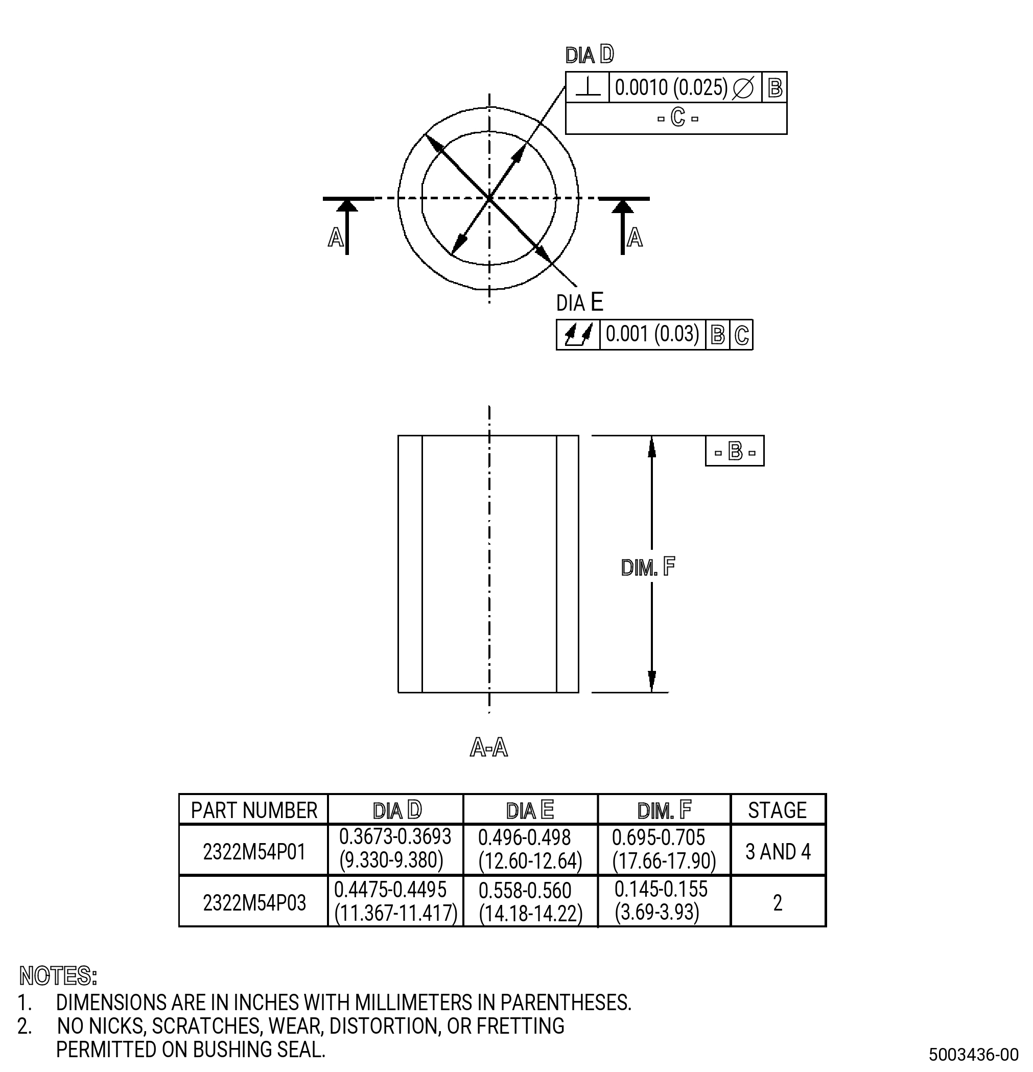
| (3) | Get the correct new or serviceable bushing seal as follows: |
| (a) | For stage 2, use bushing seal part number 2322M54P03 when any of the following bushing part numbers are installed: |
| 1 | Outer bushing part numbers 2322M52P05 , 2322M52P06 , and 2322M52P07 . |
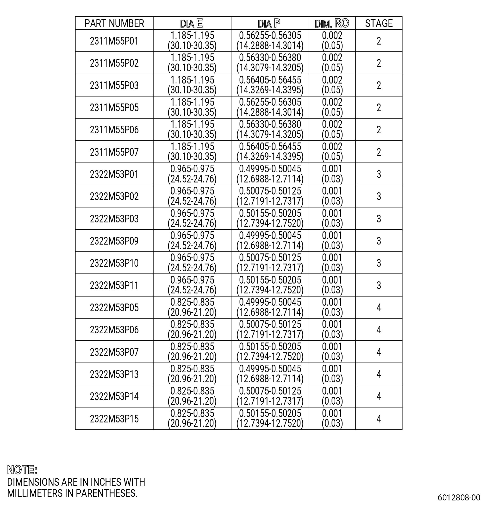
| 2 | Inner bushing part numbers 2311M55P01 , 2311M55P02 , and 2311M55P03 . |
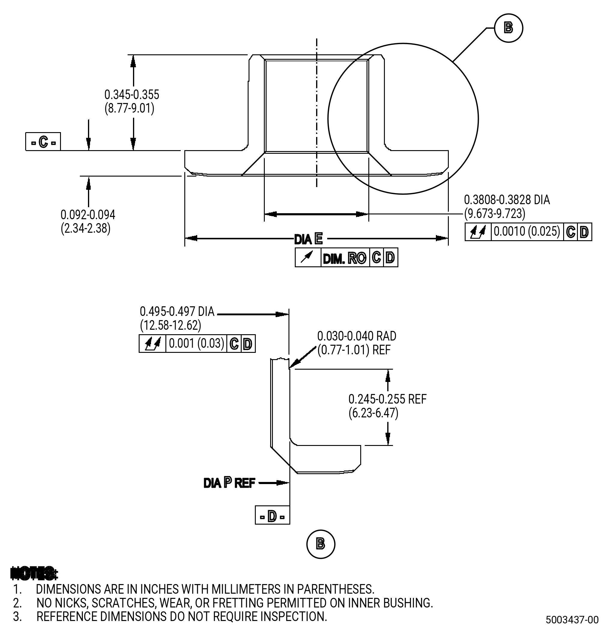
| (b) | For stage 3 and stage 4, use bushing seal part number 2322M54P01 when any of the following bushing part numbers are installed: |
| 1 | Outer bushing part numbers 2322M52P01 , 2322M52P02 , and 2322M52P03 . |
| 2 | Inner bushing part numbers 2322M53P01 , 2322M53P02 , 2322M53P03 , 2322M53P05 , 2322M53P06 , and 2322M53P07 . |
| NOTE: |
|
| (4) | Use the 11C3300 bushing installation tool. Refer to Figure 903. |
| (5) | Apply C02-033 petrolatum to the outside diameter (OD) rabbet of bushings before installing the bushing. |
| (6) | Make sure that each bushing is fully installed. |
| Subtask 72-32-01-220-055 |
| D. | Do a visual inspection of the installed bushing as follows: |
| (1) | Use 2X magnification and white light. |
| (2) | Missing coating is not permitted. |
| (3) | Linear indications in the coating are not permitted. |
| NOTE: |
|
| (4) | Indications less than 0.03 inch (0.7 mm) are not interpretable. |
| Subtask 72-32-01-220-056 |
| E. | Do a dimensional inspection of the bushing installation. Refer to Figure 904. |