| GENX-1B CLEANING,INSPECTION,AND REPAIR MANUAL | Dated: 08/13/2024 | |
| CIR 72-32-01 , INSPECTION 001 | ||
| HPC STATOR FORWARD CASE ASSEMBLY - INSPECTION | ||
| GENX-1B CLEANING,INSPECTION,AND REPAIR MANUAL | Dated: 08/13/2024 | |
| CIR 72-32-01 , INSPECTION 001 | ||
| HPC STATOR FORWARD CASE ASSEMBLY - INSPECTION | ||
| * * * FOR ALL |
| TASK 72-32-01-200-801 |
| 1 . | General. |
| A. | This procedure gives instructions to do an inspection of the HPC stator forward case assembly (case assembly) (073A0). |
| B. | The case assembly halves are a matched set. Keep them together. |
| 2 . | Tools, Equipment, and Materials. |
| NOTE: |
|
| A. | Tools and Equipment. |
| (1) | Special Tools. |
| (2) | Standard Tools and Equipment. None. |
| (3) | Locally Manufactured Tools. None. |
| B. | Consumable Materials. |
|
| C. | Referenced Procedures. |
|
| D. | Expendable Parts. None. |
| 3 . | Specific Inspection Procedure. |
| Subtask 72-32-01-230-001 |
| A. | Do a Class D spot-fluorescent-penetrant inspection of the circumferential and horizontal flanges and to verify any visual indications. Refer to TASK 70-32-03-230-002 (SPOT-FLUORESCENT-PENETRANT INSPECTION) and as follows: |
| (1) | If the circumferential aft flange boltholes have C03-038 Sermetel W paint on them, remove it. Refer to TASK 72-32-01-300-809 (72-32-01, REPAIR 009). |
| 4 . | Visual Inspection |
| Refer to Figure 801. |
| Subtask 72-32-01-220-001 |
| A. | Do an inspection of all surfaces for: |
| (1) | Cracks: |
| Maximum serviceable limit: |
|
| Repair method: |
|
| Subtask 72-32-01-220-002 |
| (2) | Nicks, pits, scores, and scratches: |
| Maximum serviceable limit: |
|
| Maximum repairable limit: |
|
| Repair method: |
|
| Subtask 72-32-01-220-003 |
| (3) | Hot spots (discoloration): |
| Maximum serviceable limit: |
|
| Repair method: |
|
| Subtask 72-32-01-220-004 |
| (4) | Discoloration on the case surfaces: |
| Maximum serviceable limit: |
|
| Repair method: |
|
| Subtask 72-32-01-220-005 |
| (5) | Corrosion on the case: |
| Maximum serviceable limit: |
|
| Maximum repairable limit: |
|
| Repair method: |
|
| Subtask 72-32-01-220-006 |
| B. | Do an inspection of the surfaces of the stages 1 and 2 rotor blade rub lands for: |
| (1) | Nicks, dents, and scratches: |
| Maximum serviceable limit: |
|
| • |
|
| • |
|
| • |
|
| • |
|
| Repair method: |
|
| Subtask 72-32-01-220-008 |
| (2) | Local scabs (positive metal pickup from the blades): |
| Maximum serviceable limit: |
|
| Maximum repairable limit: |
|
| Repair method: |
|
| Subtask 72-32-01-220-040 |
| C. | Do an inspection of the stage 3 shroud and stage 4 shroud flowpath surfaces for: |
| (1) | Rubs and gouges: |
| Maximum serviceable limit: |
|
| Repair method: |
|
| Subtask 72-32-01-220-041 |
| (2) | Nicks, dents, and scratches: |
| Maximum serviceable limit: |
|
| Repair method: |
|
| Subtask 72-32-01-220-042 |
| (3) | Local scabs (positive metal pickup from the blades): |
| Maximum serviceable limit: |
|
| Maximum repairable limit: |
|
| Repair method: |
|
| Subtask 72-32-01-220-009 |
| D. | Do an inspection of the horizontal flanges for: |
| (1) | Cracks: |
| Maximum serviceable limit: |
|
| Repair method: |
|
| Subtask 72-32-01-220-010 |
| (2) | Nicks and dents on the mating surface: |
| Maximum serviceable limit: |
|
| Maximum repairable limit: |
|
| Repair method: |
|
| Subtask 72-32-01-220-011 |
| (3) | Fretting or galling on the mating surface: |
| Maximum serviceable limit: |
|
| Maximum repairable limit: |
|
| Repair method: |
|
| Subtask 72-32-01-220-012 |
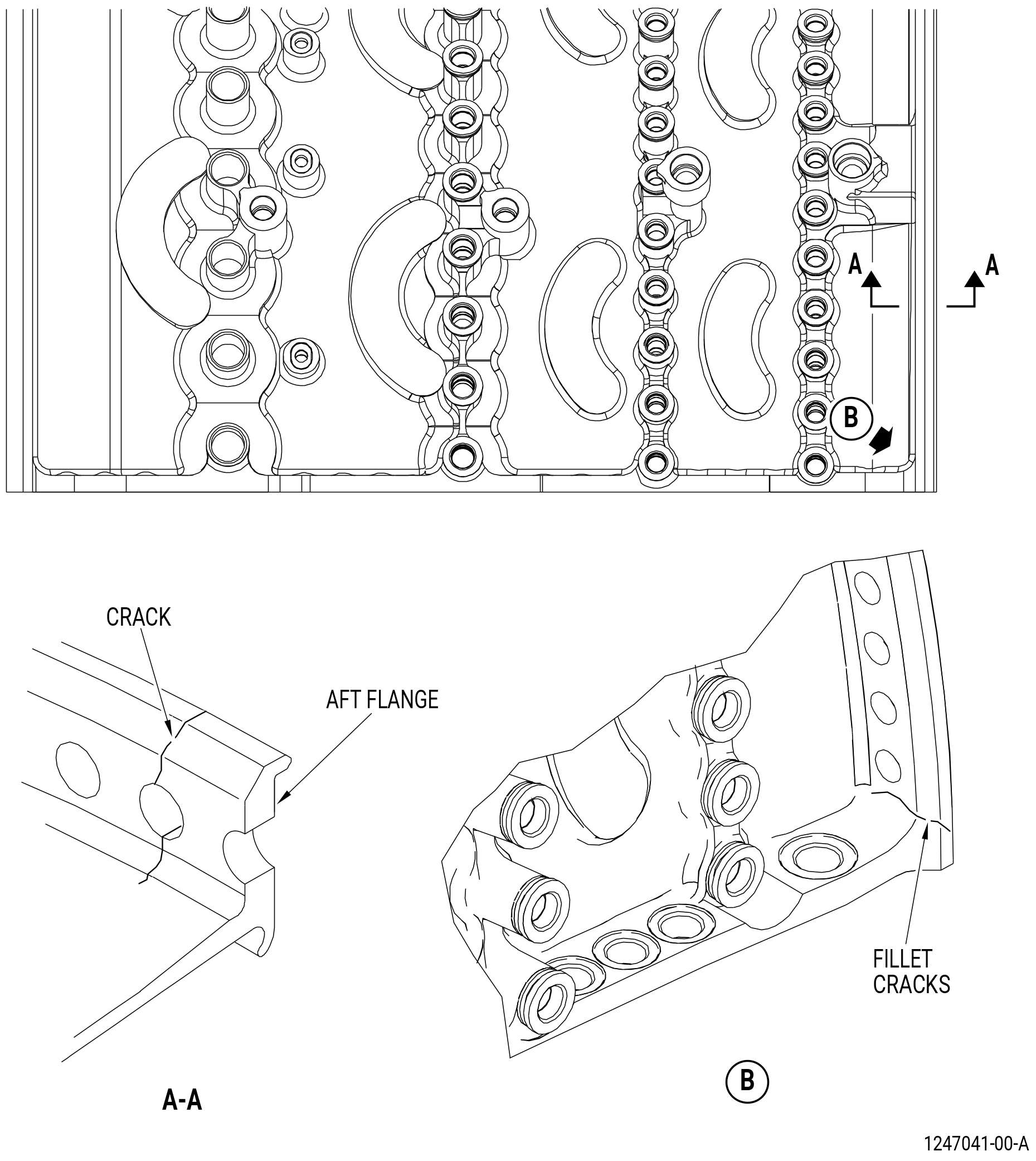
| E. | Do an inspection of the circumferential flanges for the following. Refer to Figure 802. |
| (1) | Cracks: |
| Maximum serviceable limit: |
|
| Repair method: |
|
| Subtask 72-32-01-220-013 |
| (2) | Nicks and scratches on the mating surface: |
| Maximum serviceable limit: |
|
| Maximum repairable limit: |
|
| Repair method: |
|
| Repair method: |
|
| Subtask 72-32-01-220-014 |
| (3) | Cracks in the fillet between the aft circumferential flange and the horizontal flange. Refer to Figure 802. |
| Maximum serviceable limit: |
|
| Repair method: |
|
| Subtask 72-32-01-220-015 |
| (4) | Fretting or galling on the mating surface: |
| Maximum serviceable limit: |
|
| Maximum repairable limit: |
|
| Repair method: |
|
| Repair method: |
|
| Subtask 72-32-01-220-131 |
| (5) | Corrosion pitting in the aft circumferential flange boltholes: |
| Maximum serviceable limit: |
|
| Repair method: |
|
| Subtask 72-32-01-220-016 |
| F. | Do an inspection of the stage 1 VSV bore area and stage 2-4 bushing areas for: |
| (1) | Nicks and scratches (this does not include the mating surfaces): |
| Maximum serviceable limit: |
|
| Repair method: |
|
| Subtask 72-32-01-220-017 |
| (2) | Nicks and scratches on the mating surfaces: |
| Maximum serviceable limit: |
|
| Maximum repairable limit: |
|
| Repair method: |
|
| Maximum repairable limit: |
|
| Repair method: |
|
| Subtask 72-32-01-220-018 |
| (3) | Wear or damage on the ID of the counterbore: |
| Maximum serviceable limit: |
|
| Maximum repairable limit: |
|
| Repair method: |
|
| Maximum repairable limit: |
|
| Repair method: |
|
| Subtask 72-32-01-220-019 |
| (4) | Wear in the bore: |
| Maximum serviceable limit: |
|
| Repair method: |
|
| Subtask 72-32-01-220-057 |
| (5) | Fretting or galling on the stage 2, 3, and 4 bushing mating surfaces: |
| Maximum serviceable limit: |
|
| Repair method: |
|
| Subtask 72-32-01-220-058 |
| G. | Do an inspection of the plug bolts (bolts) (07320), if installed in the HPC stator case mounting boss (boss) for. Refer to Figure 801. |
| (1) | Loose, broken or missing bolts in the boss: |
| Maximum serviceable limit: |
|
| Maximum repairable limit: |
|
| Repair method: |
|
| Subtask 72-32-01-220-020 |
| * * * PRE SB 72-0356 |
| H. | Do an inspection of the self-locking inserts of the mounting pads, bosses, and aft circumferential flange for: |
| (1) | Loss of self-locking quality of the 0.250-28UNF-3B insert (mounting pads and bosses): |
| Maximum serviceable limit: |
|
| Repair method: |
|
| Subtask 72-32-01-220-021 |
| (2) | Loss of self-locking quality of the 0.375-24UNF-3B insert (aft circumferential flange): |
| Maximum serviceable limit: |
|
| Repair method: |
|
| Subtask 72-32-01-220-022 |
| (3) | Loose or missing insert: |
| Maximum serviceable limit: |
|
| Repair method: |
|
| * * * END PRE SB 72-0356 |
| Subtask 72-32-01-220-122 |
| * * * SB 72-0356 |
| H.A. | Do an inspection of the key-locked insert for: |
| (1) | Loss of self-locking quality: |
| Maximum serviceable limit: |
|
| Repair method: |
|
| Subtask 72-32-01-220-123 |
| (2) | Looseness or missing: |
| Maximum serviceable limit: |
|
| Repair method: |
|
| * * * END SB 72-0356 |
| Subtask 72-32-01-220-023 |
| I. | Do an inspection of the borescope ports for: |
| (1) | Damaged threads: |
| Maximum serviceable limit: |
|
| Maximum repairable limit: |
|
| Repair method: |
|
| Subtask 72-32-01-220-024 |
| (2) | Wear or damage: |
| Maximum serviceable limit: |
|
| Repair method: |
|
| Subtask 72-32-01-220-025 |
| J. | Do an inspection of the horizontal flange boltholes for: |
| (1) | Wear or damage: |
| Maximum serviceable limit: |
|
| Maximum repairable limit: |
|
| Repair method: |
|
| Subtask 72-32-01-220-026 |
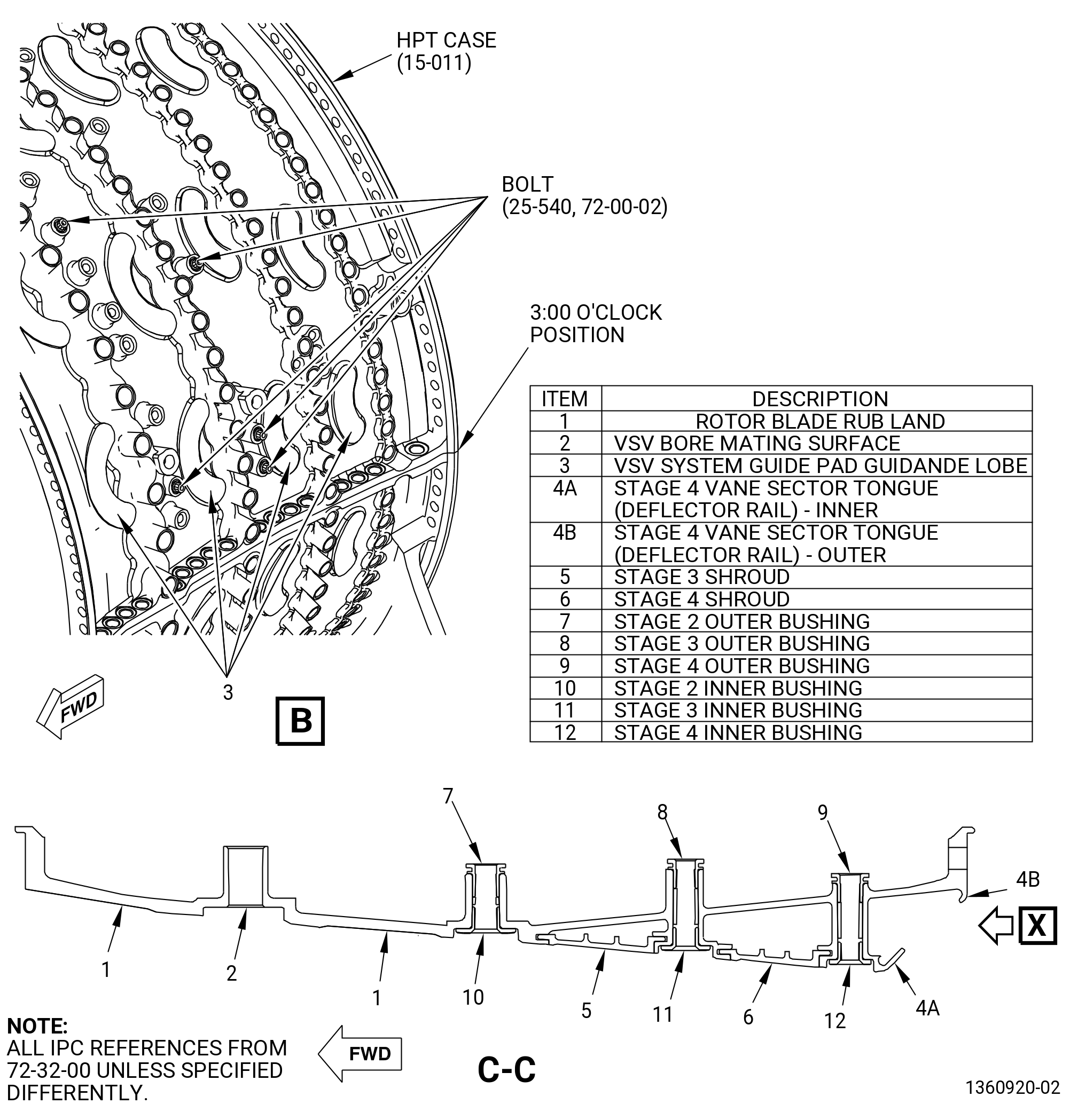
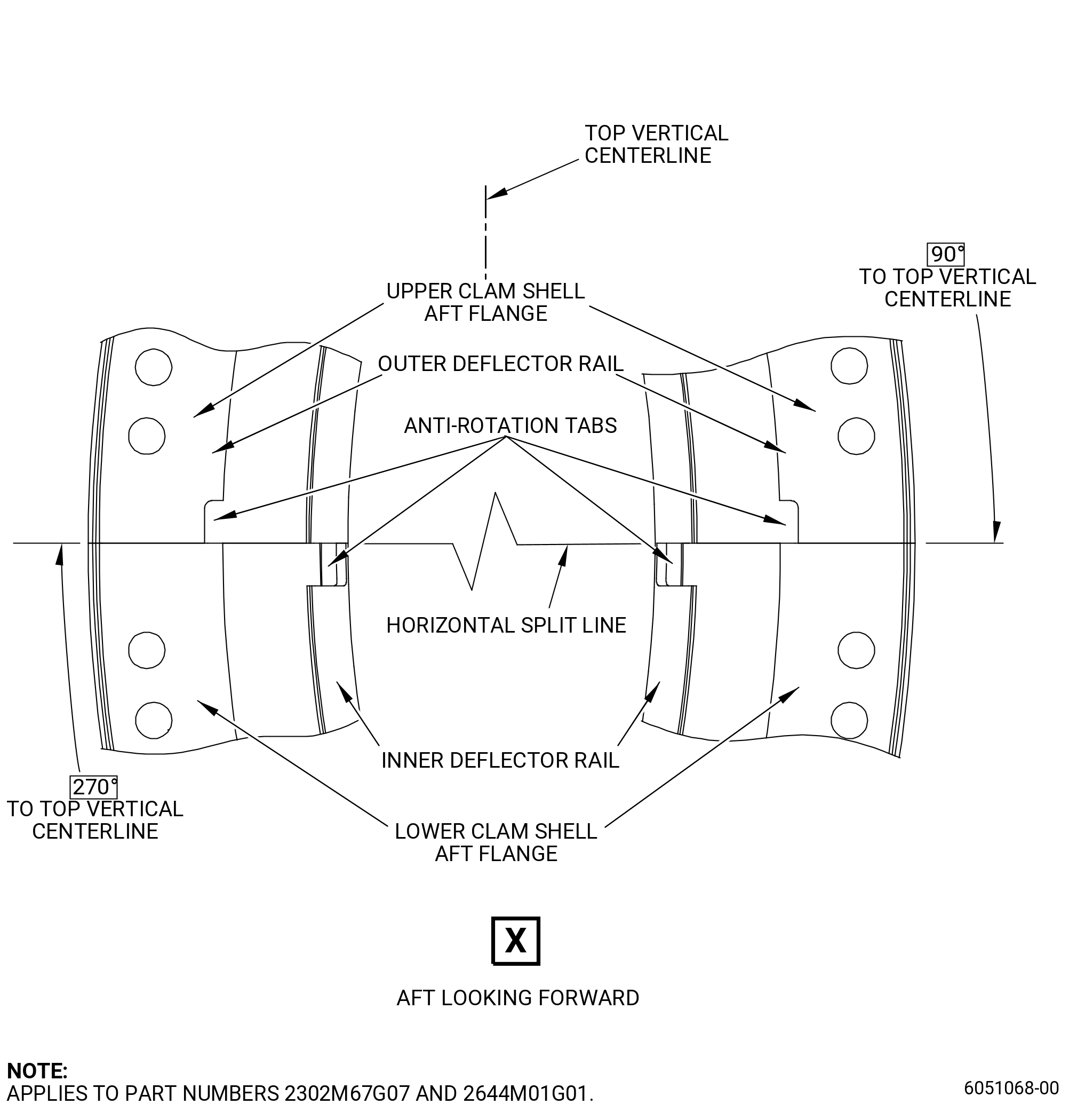
| K. | Do an inspection of the inner stage 4 vane sector tongue (deflector rail) for. Refer to Figure 801 and as follows: |
| (1) | Fretting and/or wear at the location of contact with the aft cover (deflector) not at the anti-rotation tab: |
| Maximum serviceable limit: |
|
| Repair method: |
|
| Subtask 72-32-01-220-072 |
| (2) | Fretting and/or wear at the location of contact with the aft cover (deflector) anti-rotation tab: |
| Maximum serviceable limit: |
|
| Repair method: |
|
| Subtask 72-32-01-220-104 |
| (3) | Nicks, scores, and scratches at the location of contact with the aft cover (deflector) anti-rotation tab: |
| Maximum serviceable limit: |
|
| Maximum repairable limit: |
|
| Repair method: |
|
| Subtask 72-32-01-220-117 |
| (4) | Cracks at the location of the borescope hole area A. Refer to Figure 801 and as follows: |
| Maximum serviceable limit: |
|
| Repair method: |
|
| Subtask 72-32-01-220-102 |
| L. | Do an inspection of the outer stage 4 vane sector tongue. Refer to Figure 801 and as follows: |
| (1) | Fretting and/or wear at the location of contact with the aft cover (deflector) not at the anti-rotation tab: |
| Maximum serviceable limit: |
|
| Maximum repairable limit: |
|
| Repair method: |
|
| Subtask 72-32-01-220-103 |
| (2) | Fretting and/or wear at the location of contact with the aft cover (deflector) at anti-rotation tab: |
| Maximum serviceable limit: |
|
| Repair method: |
|
| Subtask 72-32-01-220-105 |
| (3) | Nicks, scores, and scratches at the location of contact with the aft cover (deflector) anti-rotation tab: |
| Maximum serviceable limit: |
|
| Maximum repairable limit: |
|
| Repair method: |
|
| Subtask 72-32-01-220-027 |
| M. | Do an inspection of the VSV system guide pad guidance lobe for: |
| (1) | Wear and/or fretting: |
| Maximum serviceable limit: |
|
| Repair method: |
|
| Subtask 72-32-01-220-043 |
| N. | Do an inspection in the AGB mount spherical bearings of the HPC forward lower case assembly as follows. Refer to Figure 803. |
| (1) | Circumferential movement of the ball: |
| Maximum serviceable limit: |
|
| Repair method: |
|
| Subtask 72-32-01-220-046 |
| (2) | Axial looseness of the outer race in the AGB mount: |
| Maximum serviceable limit: |
|
| Repair method: |
|
| Subtask 72-32-01-220-047 |
| (3) | Nicks, dents, and scratches of the spherical surfaces and the ID (diameter BA and BB) of the ball: |
| Maximum serviceable limit: |
|
| Repair method: |
|
| Subtask 72-32-01-220-048 |
| (4) | Galling, fretting, or wear of the spherical surfaces, the ID (diameters BA and BB), and lateral faces of the ball: |
| Maximum serviceable limit: |
|
| Repair method: |
|
| Subtask 72-32-01-220-049 |
| (5) | Radial movement of the ball: |
| Maximum serviceable limit: |
|
| Repair method: |
|
| Subtask 72-32-01-220-050 |
| (6) | Axial movement of the ball: |
| Maximum serviceable limit: |
|
| Repair method: |
|
| Subtask 72-32-01-220-044 |
| O. | Do an inspection of the AGB mounts for: |
| (1) | Cracks: |
| Maximum serviceable limit: |
|
| Repair method: |
|
| Subtask 72-32-01-220-051 |
| (2) | Nicks, dents, and scratches (does not include spherical bearing): |
| Maximum serviceable limit: |
|
| Repair method: |
|
| Subtask 72-32-01-220-052 |
| (3) | Wear, fretting, and galling on the AGB support mount lugs: |
| Maximum serviceable limit: |
|
| Repair method: |
|
| Subtask 72-32-01-220-073 |
| P. | Deleted. |
| 5 . | Dimensional Inspection. |
| Refer to Figure 804 and Figure 805. |
| Subtask 72-32-01-220-028 |
| A. | Assemble the upper and lower case halves to do a dimensional inspection as follows: |
| NOTE: |
|
| (1) | Apply C02-001 lubricant to the threads and washer surfaces of the bolts and nuts. |
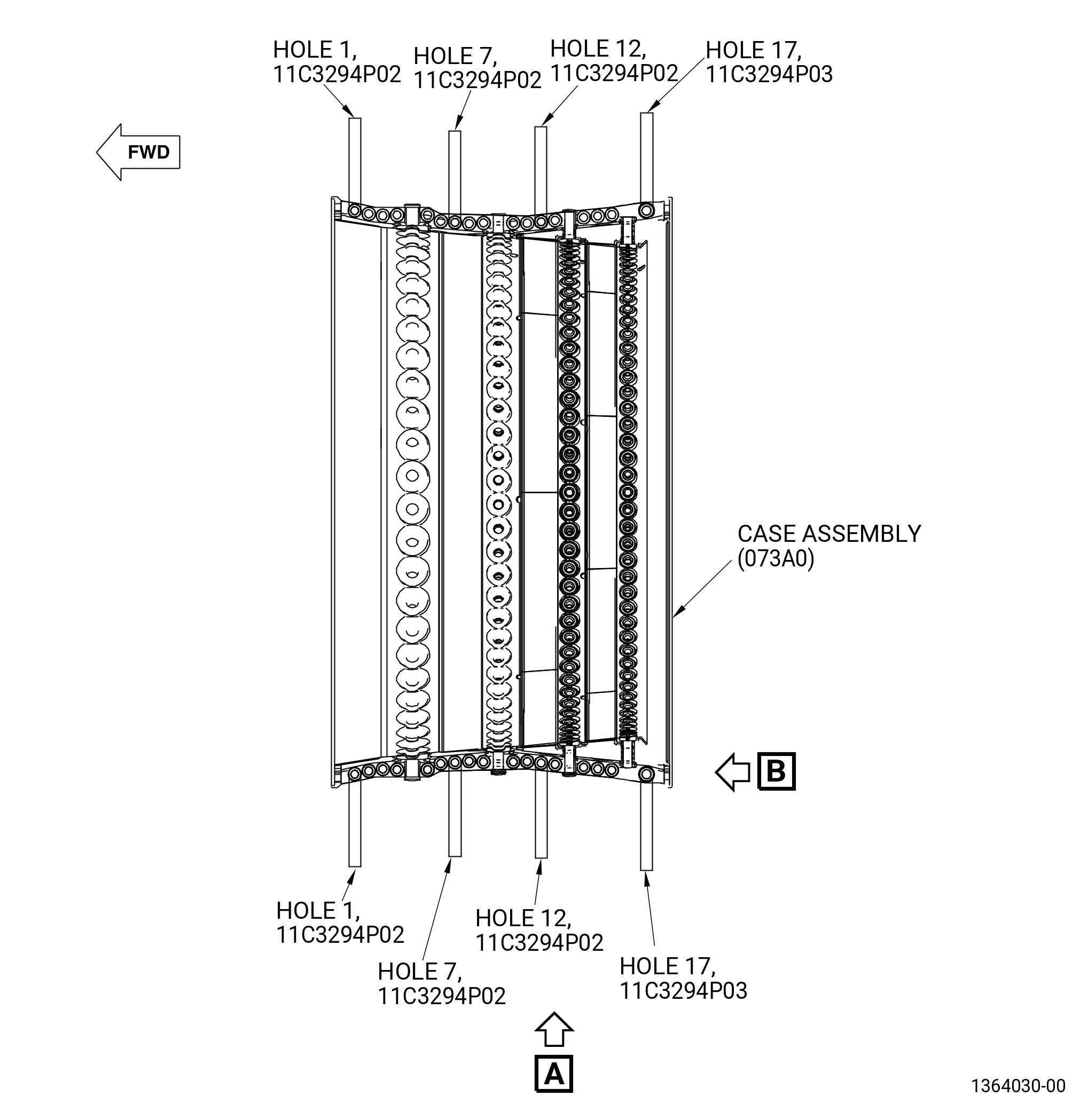
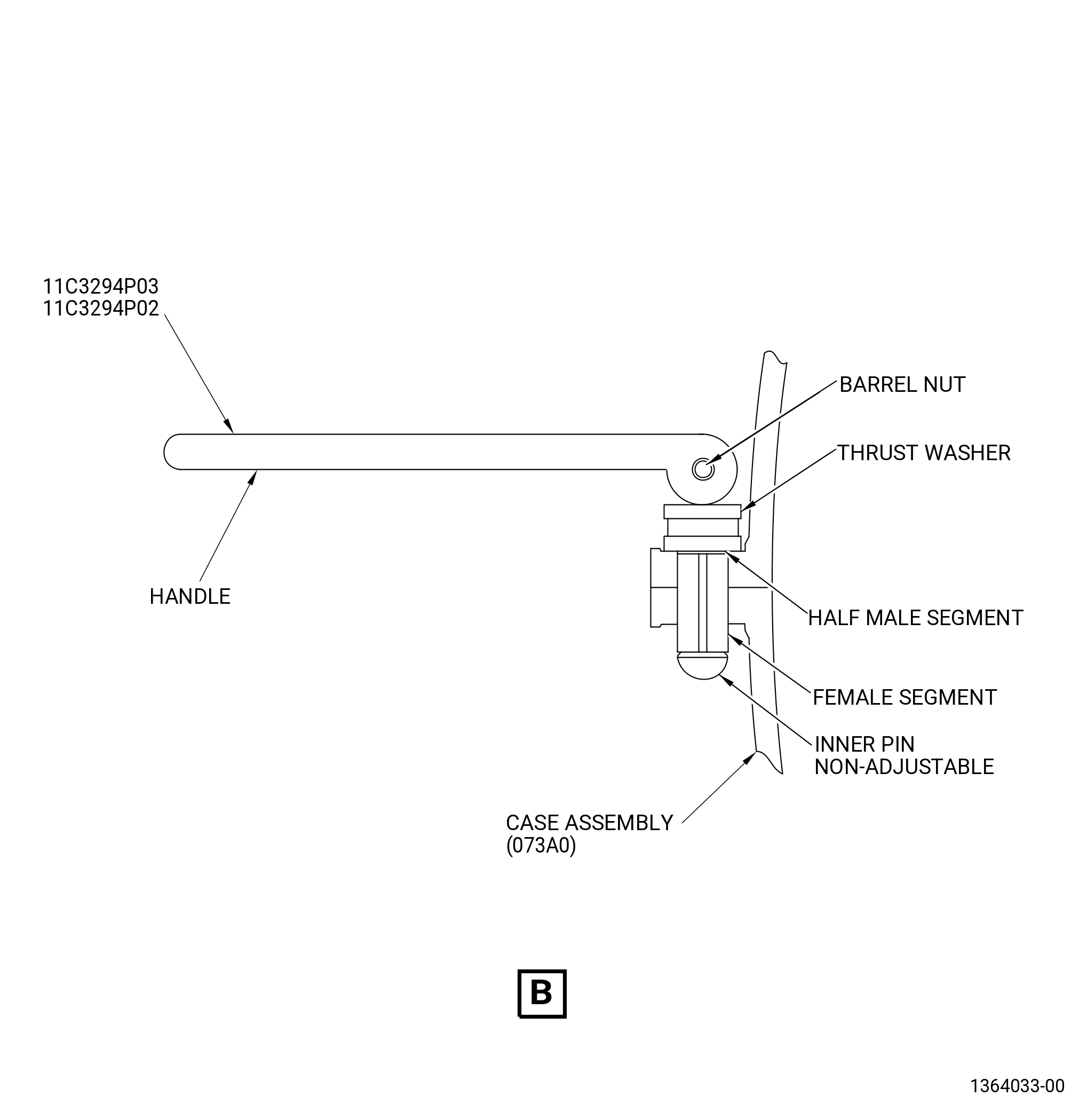
| (2) | Install the 11C3294 guide pin set from aft to forward at boltholes 17, 12, 7, and 1 to align the flanges. |
| (3) | Install the bolts and nuts in the remaining boltholes in the horizontal flange. |
| (4) | Tighten the nuts until they touch the horizontal flange. Start from bolthole No. 16. Move from one flange to the other when the nuts are tightened. |
| (5) | Torque the nuts in the same sequence to 590-610 lb in. (66.7-68.9 N.m). |
| (6) | Remove the 11C3294 guide pin set from the boltholes and install bolts and nuts in the boltholes 17, 12, 7, and 1. Torque nuts until they touch the horizontal flanges. |
| (7) | Torque the nuts at bolthole No. 17 to 890-910 lb in. (100.6-102.8 N.m). Torque the nuts at boltholes 12, 7, and 1 to 590-610 lb in. (66.7-68.9 N.m). Start from bolthole No. 12. Move from one flange to the other when the nuts are tightened. |
| (8) | Measure all dimensions in free state. The reference axis is established by diameter A and surface B. |
| Subtask 72-32-01-220-029 |
| B. | Do a dimensional inspection as follows. Measure each diameter at 10 equally spaced locations. Calculate the average diameter dimension. Compare the average diameter to the dimensions that follow: |
| (1) | Diameter A: |
| Minimum serviceable limit: |
|
| Maximum serviceable limit: |
|
| Repair method: |
|
| Subtask 72-32-01-220-030 |
| (2) | Diameter D: |
| Minimum serviceable limit: |
|
| Maximum serviceable limit: |
|
| Repair method: |
|
| Subtask 72-32-01-220-031 |
| (3) | Surface G (horizontal flange mating surface) flatness: |
| Maximum serviceable limit: |
|
| Repair method: |
|
| Subtask 72-32-01-220-059 |
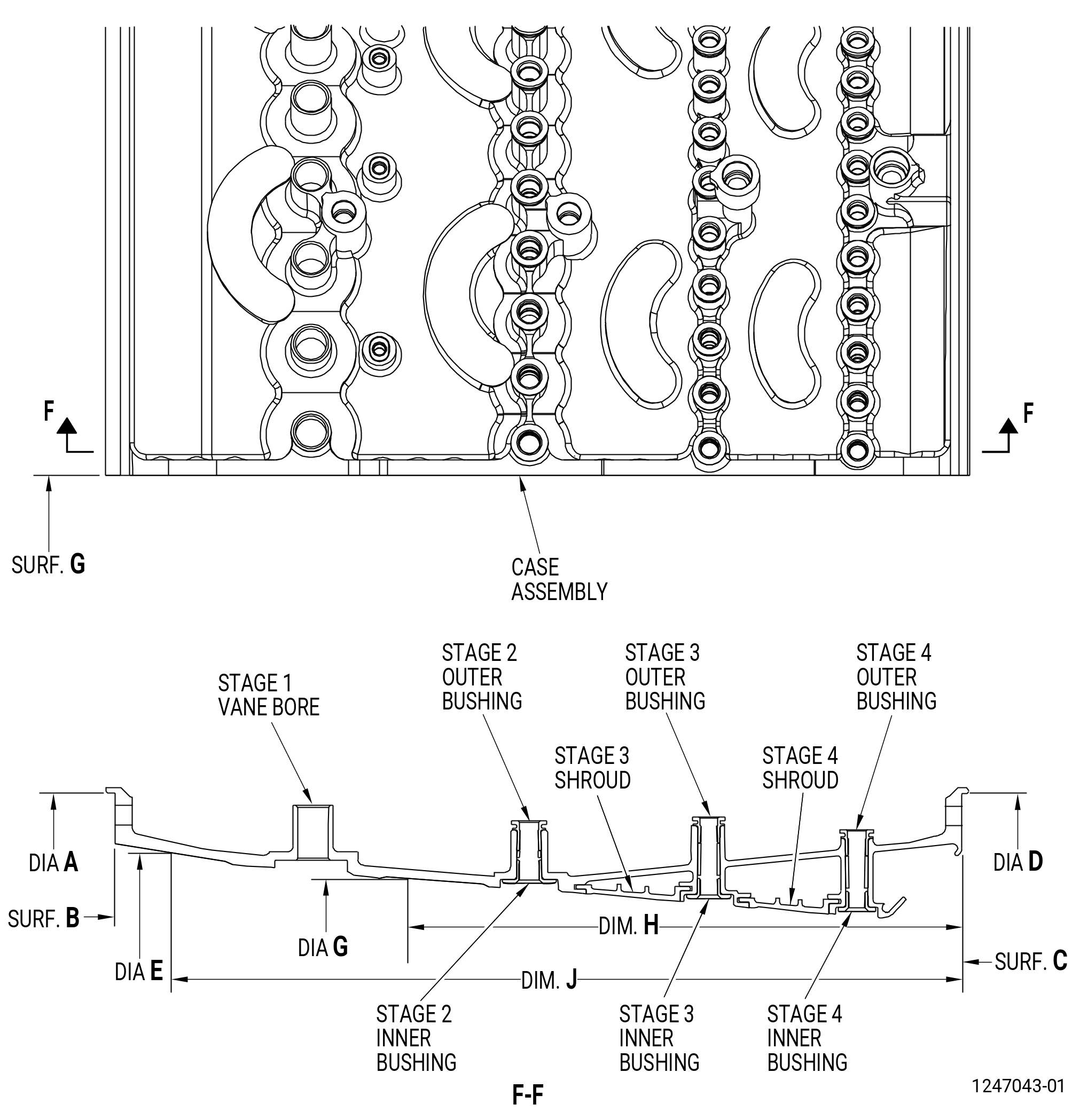
| (4) | Diameter E at a point of 17.195 inches (436.75 mm) (dimension J) from surface C: |
| Maximum serviceable limit: |
|
| Repair method: |
|
| Subtask 72-32-01-220-060 |
| (5) | Diameter G at a point of 11.449 inches (290.80 mm) (dimension H) from surface C: |
| Maximum serviceable limit: |
|
| Repair method: |
|
| Subtask 72-32-01-220-061 |
| (6) | Surface B flatness: |
| Maximum serviceable limit: |
|
| Repair method: |
|
| Subtask 72-32-01-220-062 |
| (7) | Surface B parallel to surface C: |
| Maximum serviceable limit: |
|
| Repair method: |
|
| Subtask 72-32-01-220-063 |
| (8) | Diameter D concentric with reference axis: |
| Maximum serviceable limit: |
|
| Repair method: |
|
| Subtask 72-32-01-220-064 |
| (9) | Diameter D roundness: |
| Maximum serviceable limit: |
|
| Repair method: |
|
| Subtask 72-32-01-220-065 |
| (10) | Diameter A roundness: |
| Maximum serviceable limit: |
|
| Repair method: |
|
| Subtask 72-32-01-220-045 |
| C. | Measure the diameters of the AGB mount as follows. Refer to Figure 803. |
| (1) | Diameter BA: |
| Minimum serviceable limit: |
|
| Maximum serviceable limit: |
|
| Repair method: |
|
| Subtask 72-32-01-220-053 |
| (2) | Diameter BB: |
| Minimum serviceable limit: |
|
| Maximum serviceable limit: |
|
| Repair method: |
|
| 6 . | Special Dimensional Inspection. |
| Refer to Figure 805. |
| NOTE: |
|
| Subtask 72-32-01-220-035 |
| A. | Do a dimensional inspection as follows: |
| (1) | Diameter of boltholes No. 1, 4, 7, 12, and 15: |
| Maximum serviceable limit: |
|
| Repair method: |
|
| Subtask 72-32-01-220-036 |
| (2) | Diameter of bolthole No. 17: |
| Maximum serviceable limit: |
|
| Repair method: |
|
| Subtask 72-32-01-220-037 |
| (3) | Stage 1 vane bore diameters: |
| Minimum serviceable limit: |
|
| Maximum serviceable limit: |
|
| Repair method: |
|
| Subtask 72-32-01-220-038 |
| (4) | Stage 2 bushing diameters: |
| Maximum serviceable limit: |
|
| Repair method: |
|
| Subtask 72-32-01-220-039 |
| (5) | Stage 3 and 4 bushing diameters: |
| Maximum serviceable limit: |
|
| Repair method: |
|