![]() | GENX-1B CLEANING,INSPECTION,AND REPAIR MANUAL | Dated: 02/28/2025 |
CIR 72-32-01 , REPAIR 003 | ||
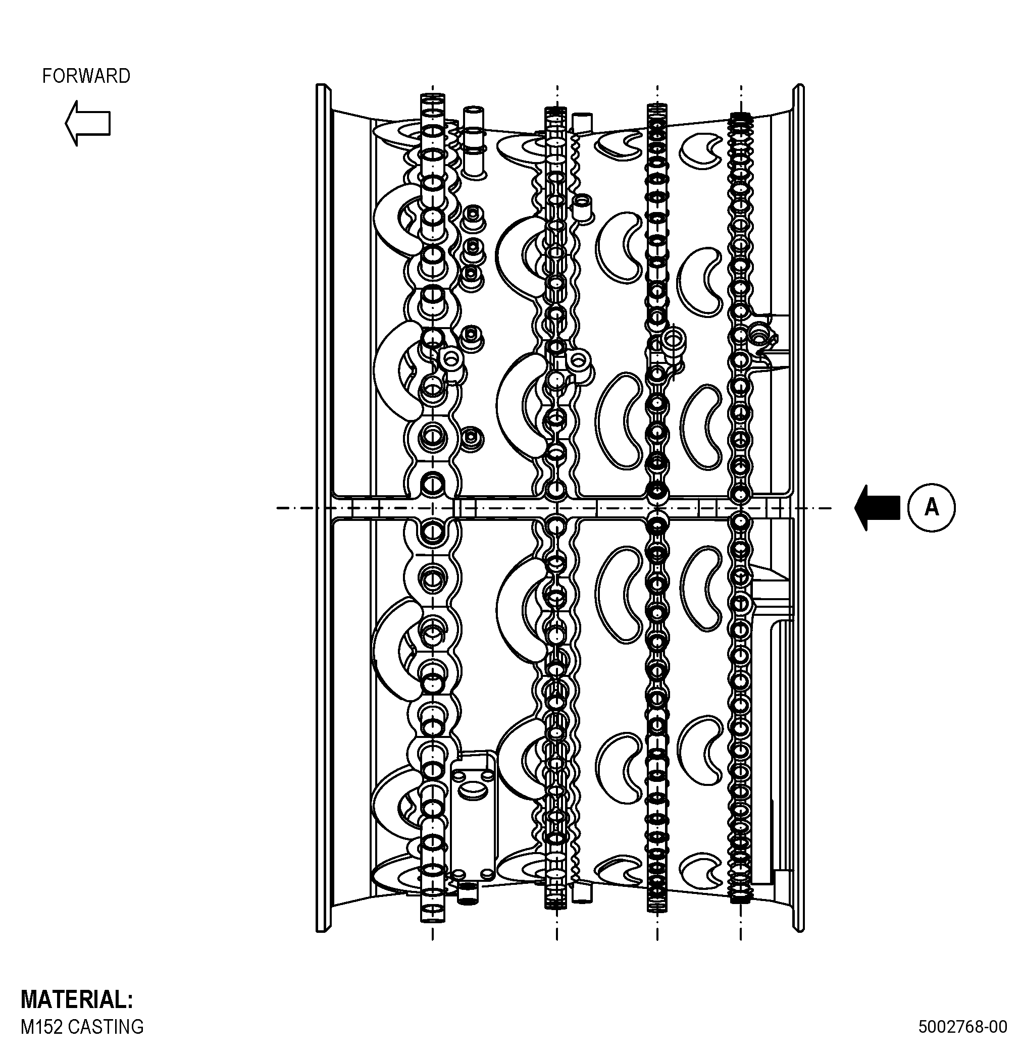
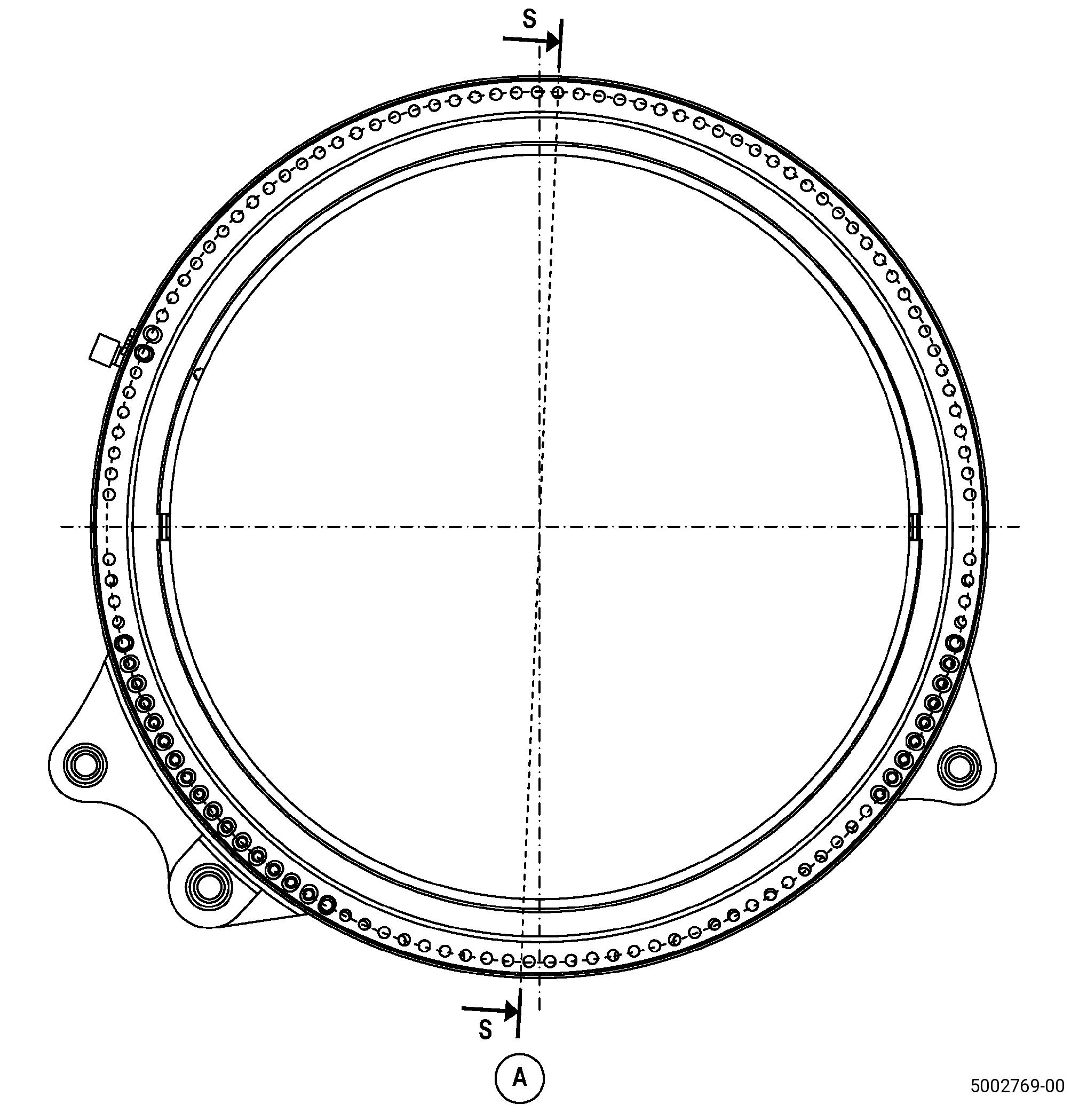
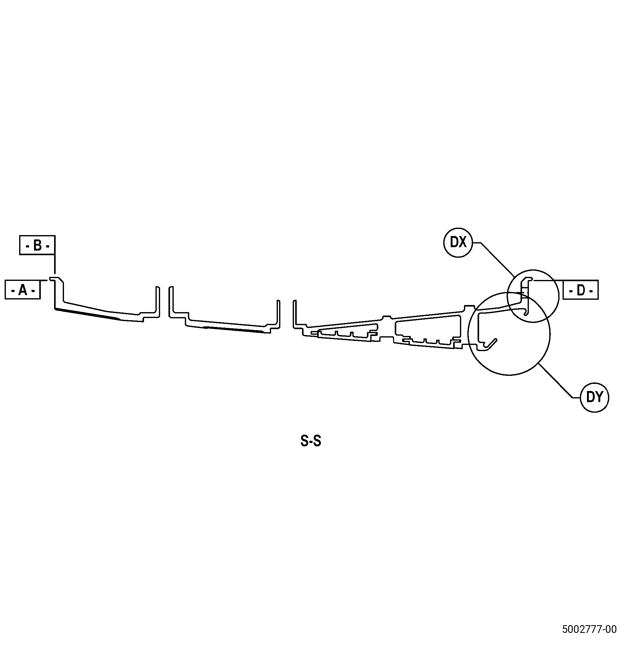
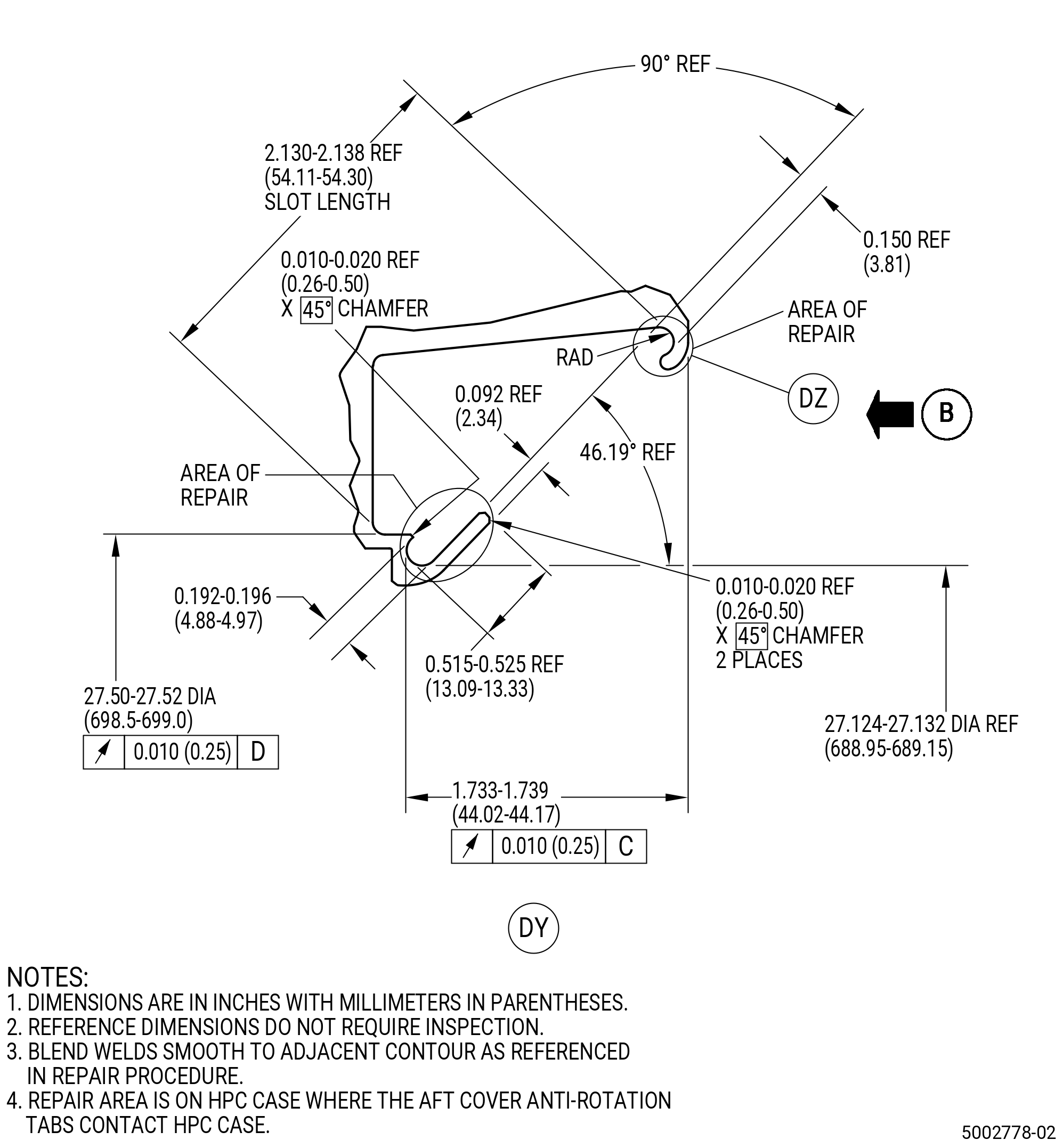
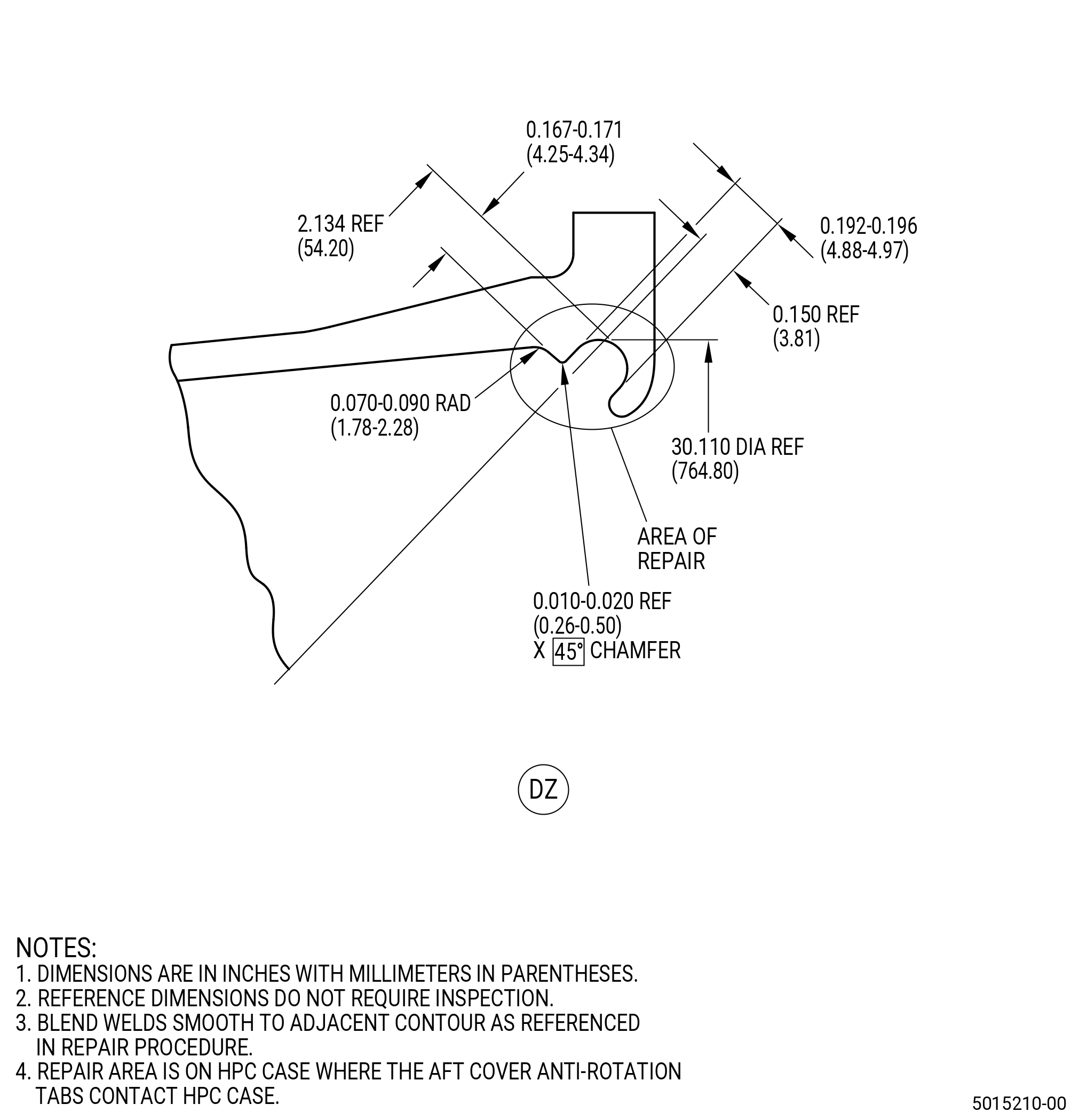
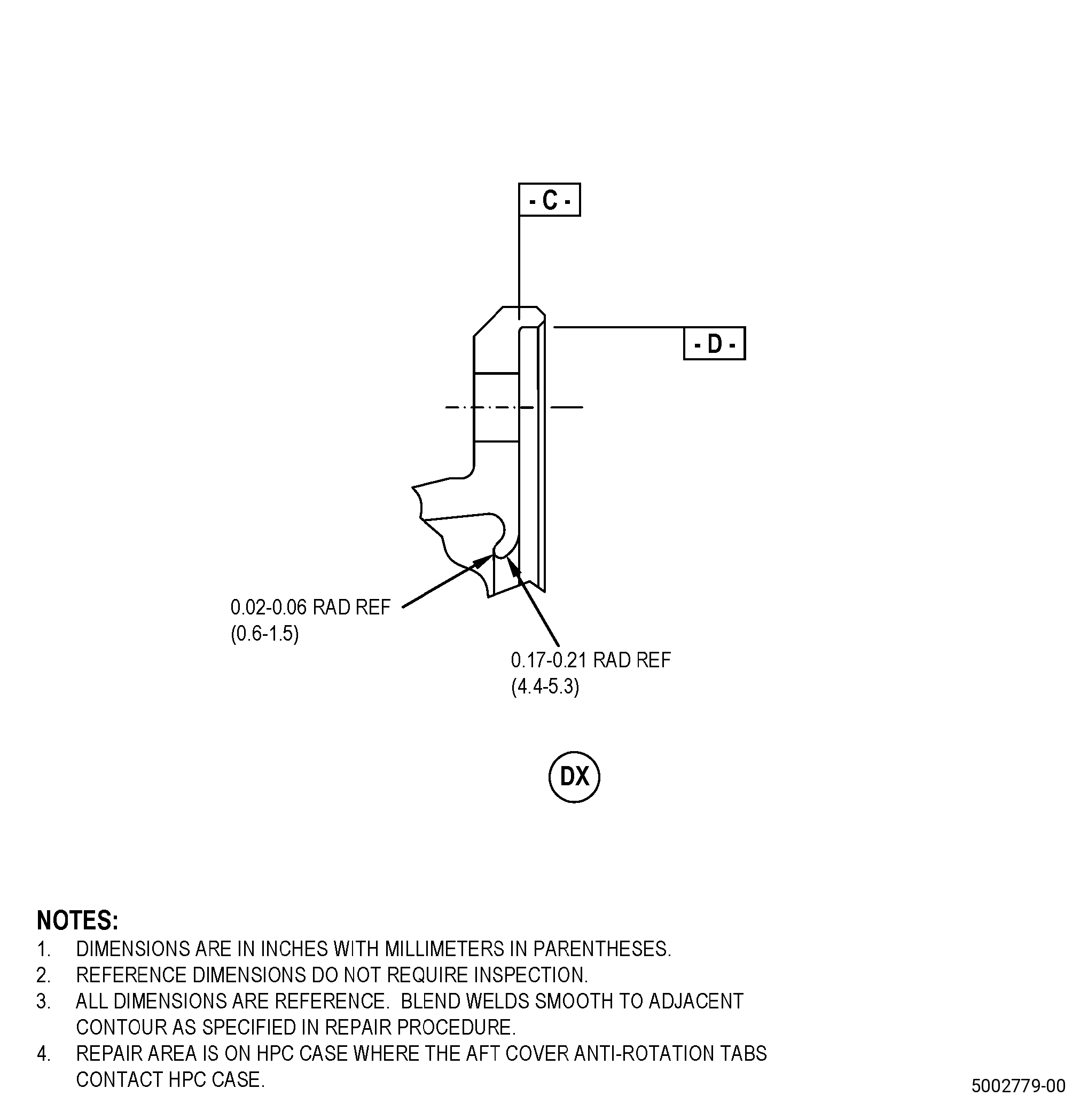
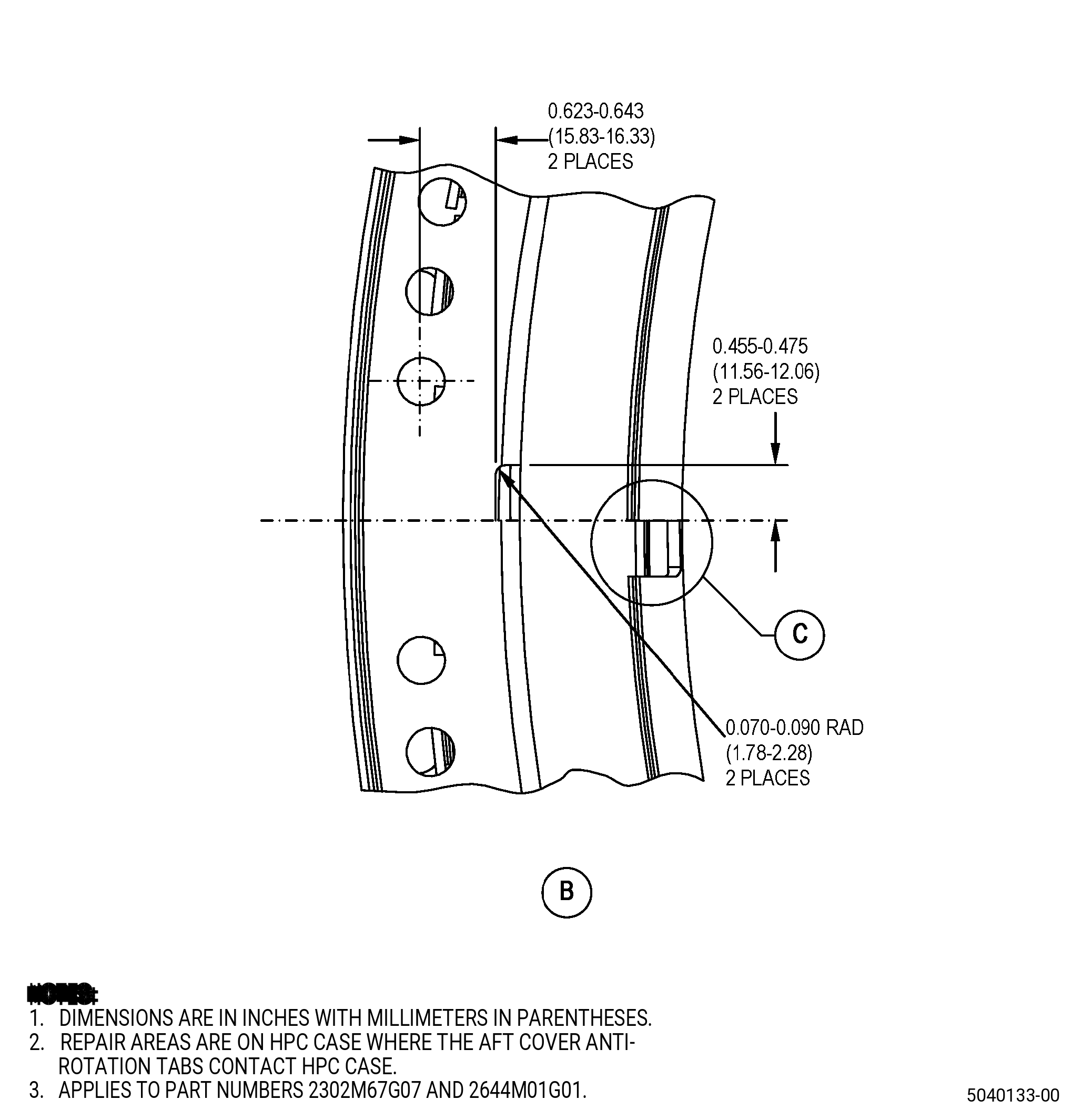
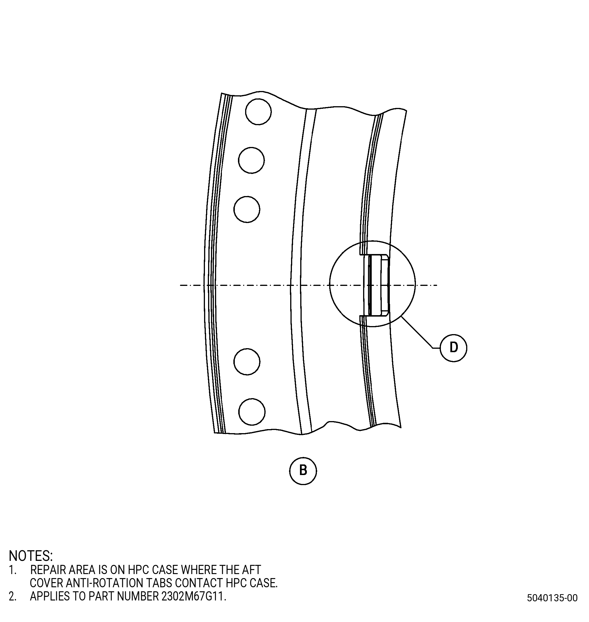
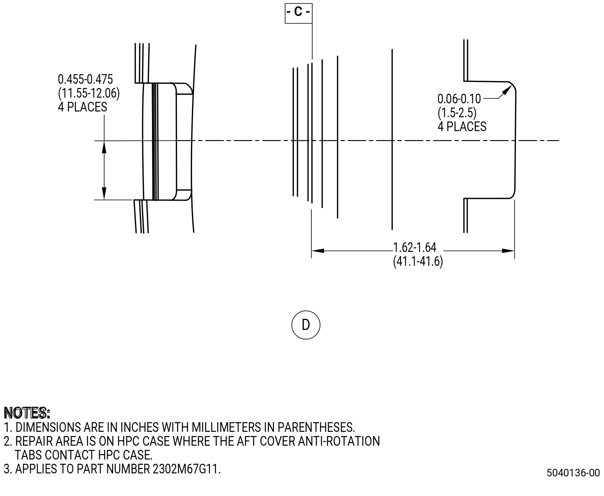
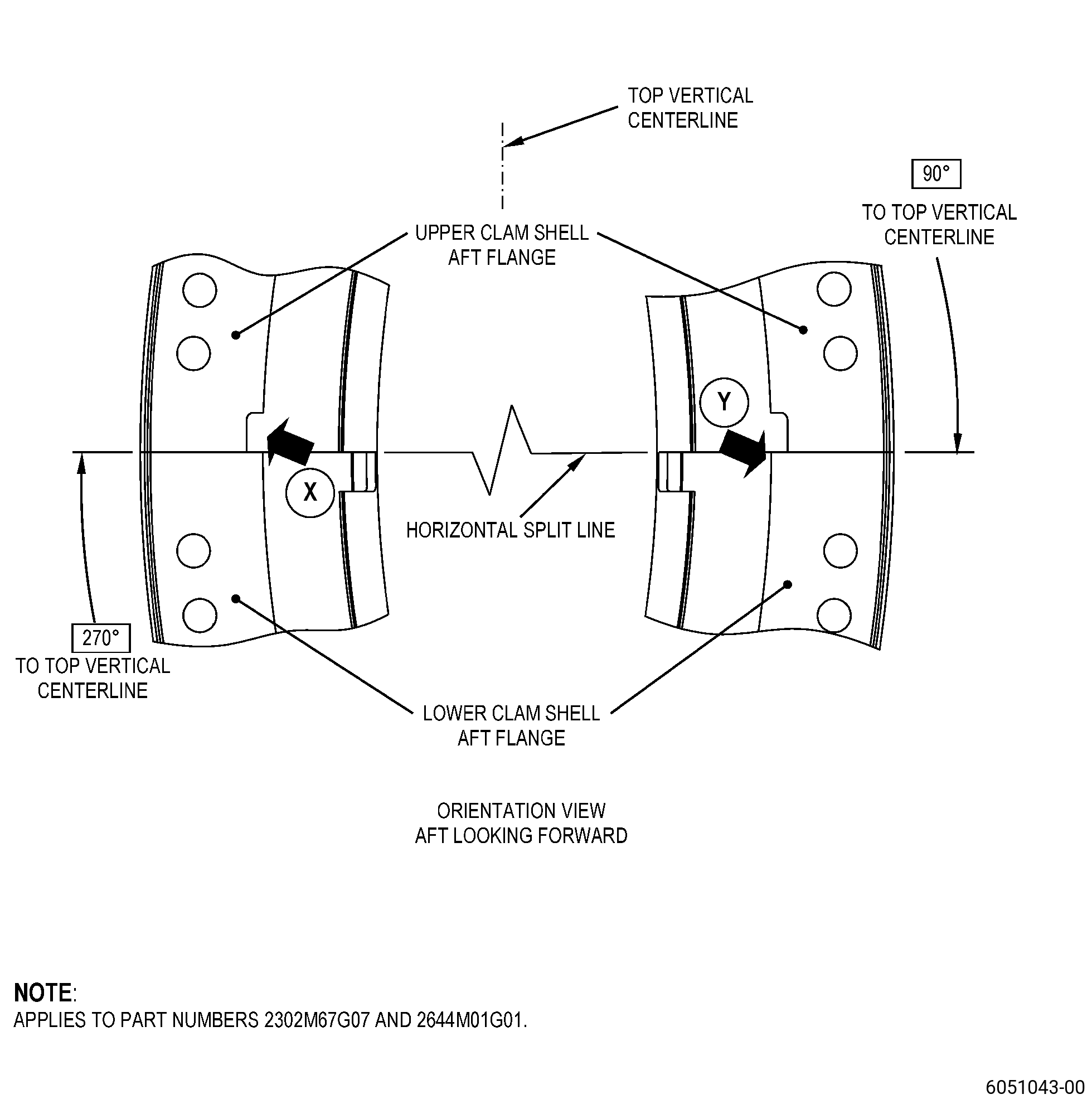
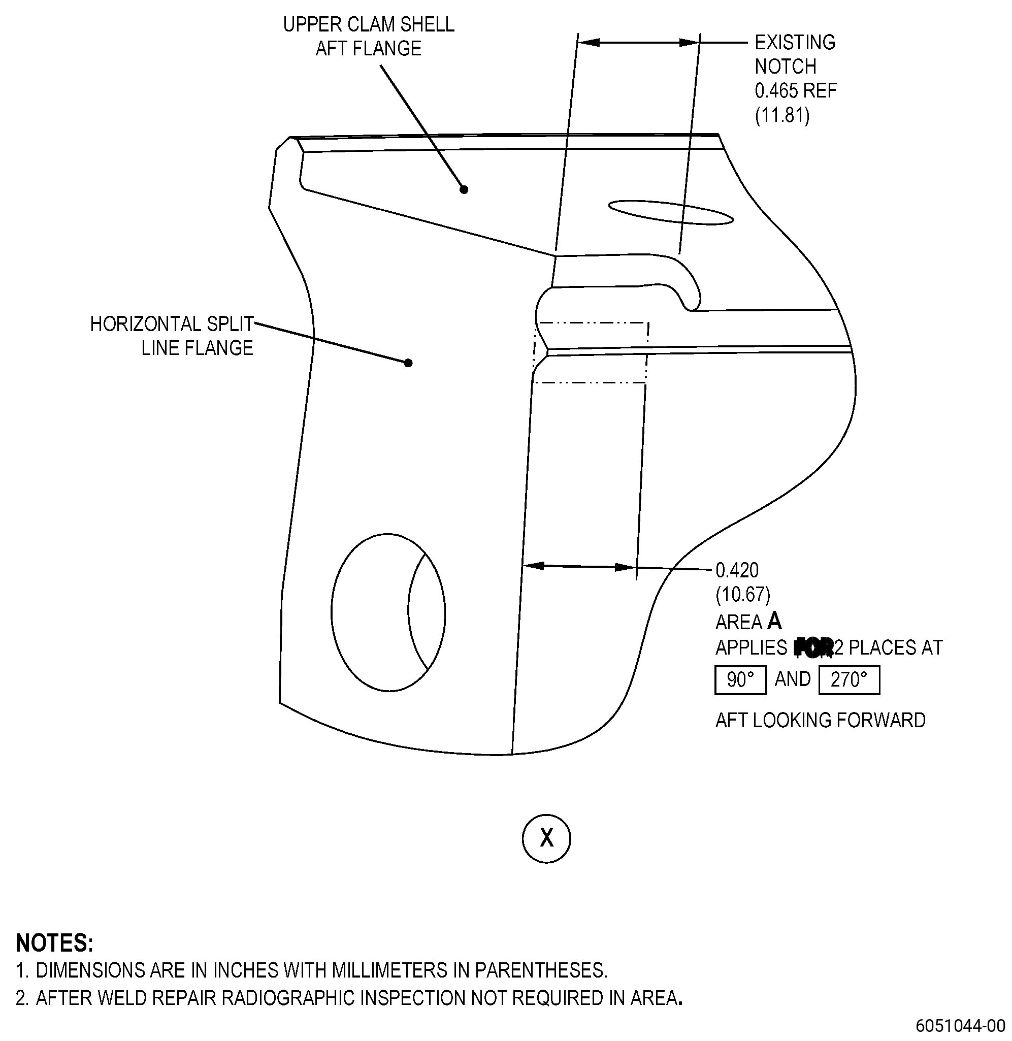
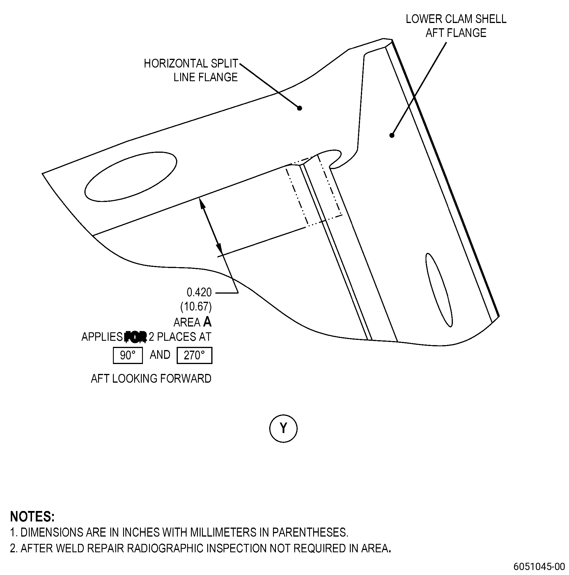
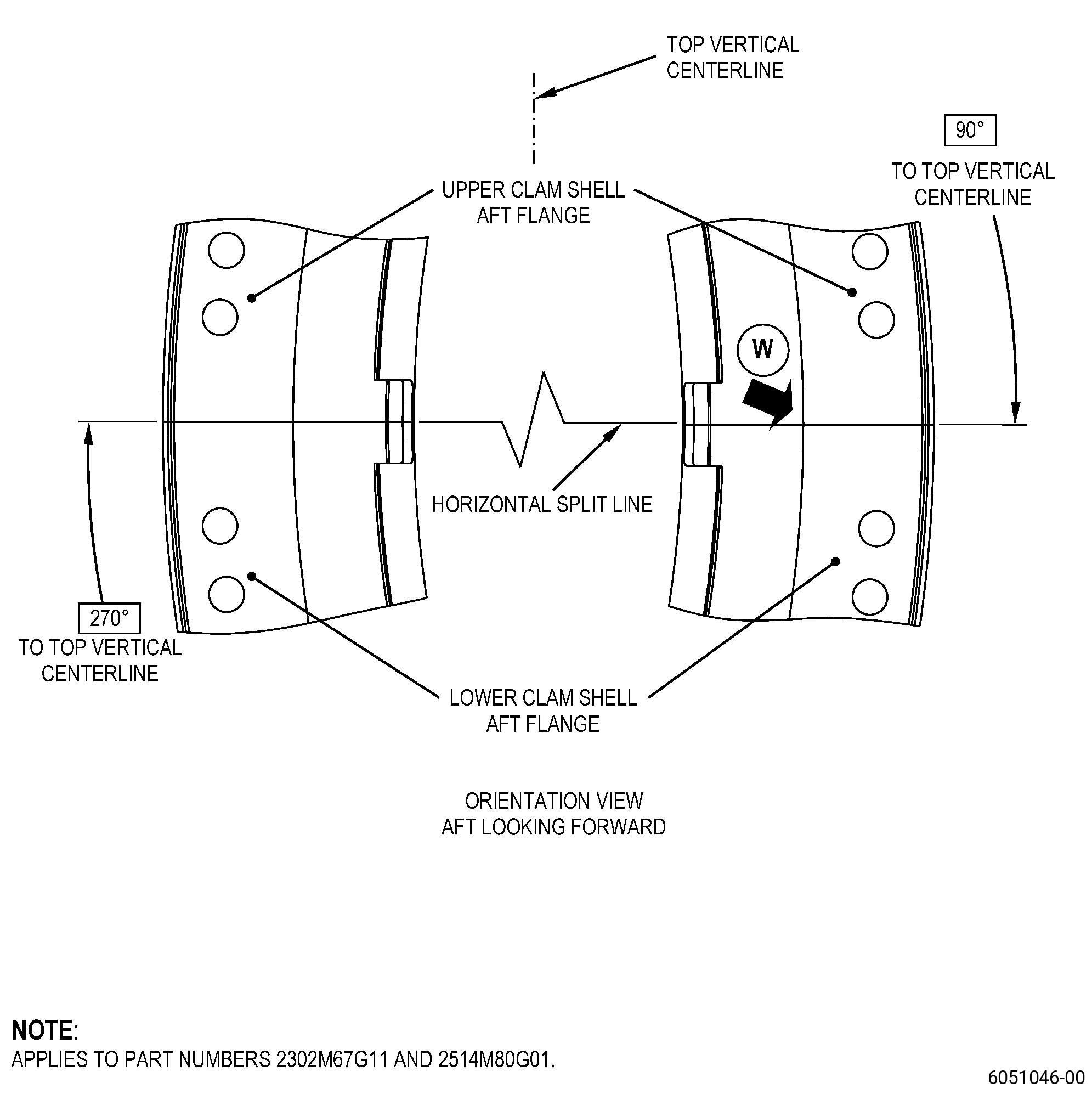
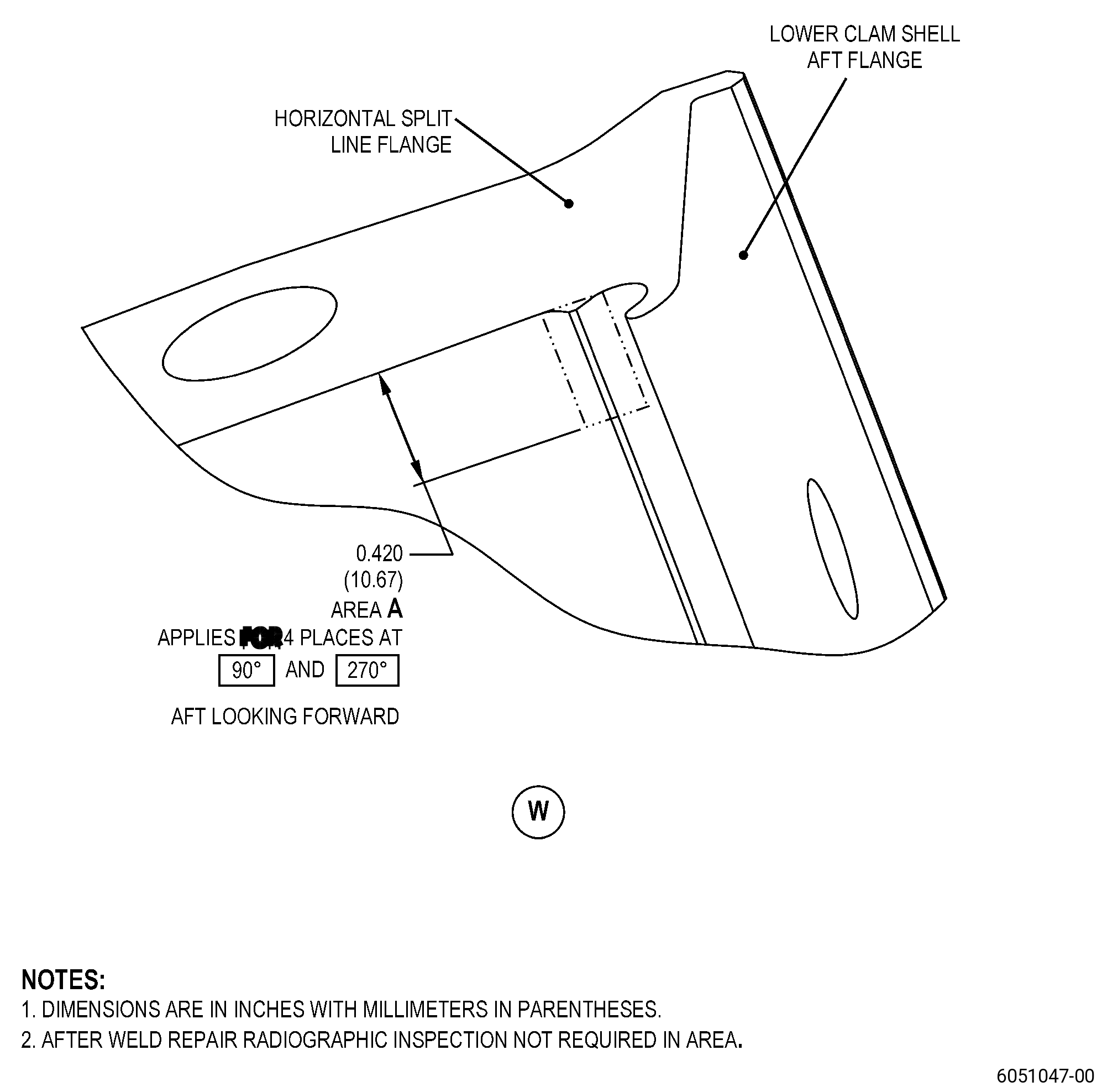
HIGH PRESSURE COMPRESSOR STATOR FORWARD CASE ASSEMBLY - REPAIR - WELD REPAIR OF THE VANE SECTOR TONGUE (DEFLECTOR RAIL) WEAR AT THE AFT COVERS ON THE FORWARD CASE | ||
* * * FOR |
TASK 72-32-01-300-803 |
1 . | Repair for the High Pressure Compressor Stator Forward Case Assembly. |
A. | This procedure gives instructions to repair the high pressure compressor (HPC) stator forward case assembly (case) by blending wear on the grooves and by welding (weld build-up) where the aft covers (deflectors) touch the case. Refer to Figure 901. |
B. | The following maximum repairable limits apply to this repair: |
NOTE: |
|
NOTE: |
|
(4) | Visual Inspection. |
(m) | Do an inspection of the inner stage 4 vane sector tongue (deflector rail) for. Refer to Figure 806 and as follows: |
1 | Fretting and/or wear at the location of contact with the aft cover (deflector) at anti-rotation tab: |
Maximum repairable limit: |
|
2 | Fretting and/or wear at the location of contact with the aft cover (deflector) not at the anti-rotation tab: |
Maximum repairable limit: |
|
(n) | Do an inspection of the outer stage 4 vane sector tongue (deflector rail) for. Refer to Figure 806 and as follows: |
1 | Fretting and/or wear at the location of contact with the aft cover (deflector) at anti-rotation tab: |
Maximum repairable limit: |
|
NOTE: |
|
(4) | Visual Inspection. |
(k) | Do an inspection of the inner stage 4 vane sector tongue (deflector rail) for. Refer to Figure 801 and as follows: |
1 | Fretting and/or wear at the location of contact with the aft cover (deflector) not at the anti-rotation tab: |
Maximum repairable limit: |
|
2 | Fretting and/or wear at the location of contact with the aft cover (deflector) at anti-rotation tab: |
Maximum repairable limit: |
|
(l) | Do an inspection of the outer stage 4 vane sector tongue for. Refer to Figure 801 and as follows: |
2 | Fretting and/or wear at the location of contact with the aft cover (deflector) at anti-rotation tab: |
Maximum repairable limit: |
|
C. | The subsequent table gives a list of the part numbers that are applicable to this repair. All part numbers are applicable to all paragraphs unless specified differently. |
|
D. | Proprietary/Complex Process Statement. |
(1) | None. |
2 . | Tools, Equipment, and Materials. |
NOTE: |
|
A. | Tools and Equipment. |
(1) | Special Tools. None. |
(2) | Standard Tools and Equipment. |
|
(3) | Locally Manufactured Tools. None. |
B. | Consumable Materials. |
|
C. | Referenced Procedures. |
D. | Expendable Parts. None. |
E. | SPD Information. |
(1) | Locally Manufactured SPD. None. |
F. | Special Solutions. None. |
G. | Test Specimens. None. |
3 . | Dimensional Information. |
Subtask 72-32-01-220-069 |
A. | Refer to Figure 901 for specified dimensions and locations. |
NOTE: |
|
NOTE: |
|
4 . | Setup Information. |
None. |
5 . | Procedure. |
Subtask 72-32-01-350-011 |
A. | If necessary, disassemble the upper and lower case assemblies of the HPC. Refer to TASK 72-32-00-040-801 (72-32-00, DISASSEMBLY 001). |
Subtask 72-32-01-350-022 |
B. | If necessary, disassemble the HPC case to remove the aft covers. Refer to TASK 72-32-00-040-801 (72-32-00, DISASSEMBLY 001). |
Subtask 72-32-01-350-012 |
C. | Alternative Procedure Available. Remove the stage 4 VSV bushings at the HPC case repair area. Refer to TASK 72-32-01-300-801 (72-32-01, REPAIR 001) and as follows: |
(1) | Remove the stage 4 VSV bushings over the circumferential length of the HPC case weld location. |
(2) | Remove four additional stage 4 VSV bushings beyond the weld location at each end of the weld area. |
Subtask 72-32-01-350-013 |
C.A. | Alternative Procedure. Remove the stage 4 VSV bushings at the HPC case repair area. Refer to TASK 72-32-01-300-801 (72-32-01, REPAIR 001) and as follows: |
(1) | Remove the stage 4 VSV bushings over the circumferential length of the HPC case weld location. |
Subtask 72-32-01-370-001 |
WARNING: |
|
(2) | Put temperature sticks at 400°F (204°C) across the four adjacent stage 4 VSV bushings beyond the weld location at each end of the weld area. Refer to Figure 901. |
Subtask 72-32-01-160-002 |
D. | Clean the HPC case. Refer to TASK 70-21-00-110-051 (CHEMICAL CLEANING) and TASK 70-21-03-160-001 (CLEANING METHOD NO. 3 - STEAM CLEANING). |
Subtask 72-32-01-230-002 |
E. | Alternative Procedure Available. Do an inspection of the HPC case. Refer to TASK 70-32-00-200-002 (INDIRECT INSPECTION METHODS), TASK 70-32-02-230-001 (FLUORESCENT PENETRANT INSPECTION), and as follows: |
(1) | Use Class A penetrant. |
(2) | Refer to TASK 72-32-01-200-801 (72-32-01, INSPECTION 001), for the acceptability limits. |
Subtask 72-32-01-230-015 |
E.A. | Alternative Procedure. Do an inspection of the HPC case repair area. Refer to TASK 70-32-00-200-002 (INDIRECT INSPECTION METHODS), TASK 70-32-03-230-002 (SPOT-FLUORESCENT-PENETRANT INSPECTION), and as follows: |
(1) | Use Class D penetrant. |
(2) | All indications less than 0.030 inch (0.76 mm) are permitted. |
(3) | Indications 0.030-0.060 inch (0.77-1.52 mm) are permitted if they agree with the conditions that follow: |
(a) | The indications are not interpreted as linear. |
NOTE: |
|
(b) | There must be a minimum distance of 0.25 inch (6.4 mm) between indications. |
Subtask 72-32-01-350-014 |
F. | Weld-repair the non-serviceable wear or indications (defects) in the HPC case repair area as follows: |
(1) | Blend the HPC case repair area to remove defects. Refer to TASK 70-42-00-350-002 (BLENDING AND REMOVAL OF HIGH METAL PROCEDURES). |
Subtask 72-32-01-110-006 |
(2) | Etch the HPC case blended areas. Refer to TASK 70-24-00-110-033 (ETCHING PROCEDURES FOR FLUORESCENT-PENETRANT INSPECTION), TASK 70-24-01-110-034 (SWAB ETCHING PROCEDURE), and as follows: |
(a) | Use Class C etchant. |
Subtask 72-32-01-230-003 |
(3) | Alternative Procedure Available. Do an inspection of the HPC case repair area. Refer to TASK 70-32-00-200-002 (INDIRECT INSPECTION METHODS), TASK 70-32-03-230-002 (SPOT-FLUORESCENT-PENETRANT INSPECTION), and as follows: |
(a) | Use Class D penetrant. |
Subtask 72-32-01-220-074 |
(b) | All indications less than 0.030 inch (0.76 mm) are permitted. |
(c) | Indications 0.030-0.060 inch (0.77-1.52 mm) are permitted if they agree with the conditions that follow: |
1 | The indications are not interpreted as linear. |
NOTE: |
|
2 | There must be a minimum distance of 0.25 inch (6.4 mm) between indications. |
Subtask 72-32-01-220-075 |
(3).A. | Alternative Procedure. Do an inspection of the HPC case repair area. Refer to TASK 70-32-00-200-002 (INDIRECT INSPECTION METHODS), TASK 70-32-19-220-001 (ENHANCED VISUAL INSPECTION), and as follows: |
(a) | All indications less than 0.030 inch (0.76 mm) are permitted. |
(b) | Indications 0.030-0.060 inch (0.77-1.52 mm) are permitted if they agree with the conditions that follow: |
1 | The indications are not interpreted as linear. |
NOTE: |
|
2 | There must be a minimum distance of 0.25 inch (6.4 mm) between indications. |
Subtask 72-32-01-350-015 |
(4) | If necessary, do the blending, etching, and inspection procedures again until all defects agree with the inspection requirements. Refer to Subtask 72-32-01-350-014 (paragraph 5.F.(1)) thru Subtask 72-32-01-230-003 (paragraph 5.F.(3)). |
Subtask 72-32-01-310-001 |
(5) | Weld the HPC case defect areas. Refer to TASK 70-41-00-310-001 (WELDING AND BRAZING PRACTICES), Figure 901, and as follows: |
(a) | Use M190 weld filler wire and argon gas backup when welding and as follows: |
1 | Weld build-up the weld metal above the contour of the adjacent parent material to blend the welds to the initial contour. |
2 | Keep the heat input into the HPC case to a minimum when you weld. Use multiple short weld passes and let the temperature of each pass decrease before you start one more pass. For large quantities of weld, pulse arc welding or skip welding procedures are recommended. |
3 | Lack of fusion, negative reinforcement, and low welds/undercuts in the welds are not permitted. |
Subtask 72-32-01-350-016 |
(6) | Blend the HPC case welded area smooth to adjacent contour. Refer to TASK 70-42-00-350-002 (BLENDING AND REMOVAL OF HIGH METAL PROCEDURES). Refer to Figure 901. |
Subtask 72-32-01-110-007 |
(7) | Etch the HPC case welded area. Refer to TASK 70-24-00-110-033 (ETCHING PROCEDURES FOR FLUORESCENT-PENETRANT INSPECTION), TASK 70-24-01-110-034 (SWAB ETCHING PROCEDURE), and as follows: |
(a) | Use Class C etchant. |
Subtask 72-32-01-230-004 |
(8) | Do an inspection of the HPC case welded area. Refer to TASK 70-32-00-200-002 (INDIRECT INSPECTION METHODS), TASK 70-32-03-230-002 (SPOT-FLUORESCENT-PENETRANT INSPECTION), and as follows: |
(a) | Use Class D penetrant. |
Subtask 72-32-01-220-076 |
(b) | All indications less than 0.030 inch (0.76 mm) are permitted. |
(c) | Indications 0.030-0.060 inch (0.77-1.52 mm) are permitted if they agree with the conditions that follow: |
1 | The indications are not interpreted as linear. |
NOTE: |
|
2 | There must be a minimum distance of 0.25 inch (6.4 mm) between indications. |
Subtask 72-32-01-260-001 |
(9) | Do an inspection of the HPC case welded area. Refer to Figure 902, TASK 70-32-00-200-002 (INDIRECT INSPECTION METHODS), TASK 70-32-05-260-001 (RADIOGRAPHIC INSPECTION), and as follows: |
(a) | The repair area on the outer rail adjacent to the horizontal split line flange specified in Figure 902 does not require radiographic inspection. |
(b) | All indications less than 0.030 inch (0.76 mm) are permitted. |
(c) | Indications 0.030-0.060 inch (0.77-1.52 mm) are permitted if they agree with the conditions that follow: |
1 | The indications are not interpreted as linear. |
NOTE: |
|
2 | There must be a minimum distance of 0.25 inch (6.4 mm) between indications. |
Subtask 72-32-01-350-017 |
(10) | If necessary, do the weld repair again until all repair welds agree with the inspection requirements of Subtask 72-32-01-230-004 (paragraph 5.F.(8)) and Subtask 72-32-01-260-001 (paragraph 5.F.(9)). Refer to Subtask 72-32-01-350-014 (paragraph 5.F.(1)) thru Subtask 72-32-01-260-001 (paragraph 5.F.(9)). |
Subtask 72-32-01-370-002 |
WARNING: |
|
G. | Do a local heat-treat of the HPC case repair area as follows: |
(1) | Increase the HPC case temperature to a temperature range of 1025 to 1075°F (552 to 579°C) for a minimum of 3 hours to make sure of the correct temperature. |
(2) | Decrease the HPC case temperature to 150°F (65°C) or less by air. |
(3) | Heat-treat the HPC case again to a temperature range of 1025 to 1075°F (552 to 579°C) for a minimum of 3 hours. |
(4) | Decrease the HPC case to room temperature by air. |
Subtask 72-32-01-350-018 |
H. | If you used temperature sticks in Subtask 72-32-01-350-013 (paragraph 5.C.A.), make sure that the temperature was not more than it is permitted as follows: |
(1) | If the temperature sticks show that the temperature was more than it is permitted, remove the stage 4 VSV bushings at that HPC case location. Refer to TASK 72-32-01-300-801 (72-32-01, REPAIR 001). |
(2) | Do Subtask 72-32-01-350-018 (paragraph 5.H.(1)) for each stage 4 VSV bushing location with temperature sticks. |
Subtask 72-32-01-230-005 |
I. | Alternative Procedure Available. Do an inspection of the HPC case. Refer to TASK 70-32-00-200-002 (INDIRECT INSPECTION METHODS), TASK 70-32-02-230-001 (FLUORESCENT PENETRANT INSPECTION), and as follows: |
(1) | Use Class A penetrant. |
(2) | Refer to TASK 72-32-01-200-801 (72-32-01, INSPECTION 001), for the acceptability limits. |
Subtask 72-32-01-230-016 |
I.A. | Alternative Procedure. Do an inspection of the HPC case repair area. Refer to TASK 70-32-00-200-002 (INDIRECT INSPECTION METHODS), TASK 70-32-03-230-002 (SPOT-FLUORESCENT-PENETRANT INSPECTION), and as follows: |
(1) | Use Class D penetrant. |
(2) | All indications less than 0.030 inch (0.76 mm) are permitted. |
(3) | Indications 0.030-0.060 inch (0.77-1.52 mm) are permitted if they agree with the conditions that follow: |
(a) | The indications are not interpreted as linear. |
NOTE: |
|
(b) | There must be a minimum distance of 0.25 inch (6.4 mm) between indications. |
Subtask 72-32-01-220-077 |
J. | Do a dimensional inspection of the HPC case. Refer to TASK 72-32-01-200-801 (72-32-01, INSPECTION 001) and as follows: |
(1) | If the HPC case is at piece part level, do a full dimensional inspection of the HPC case. |
(2) | If the HPC case is at the module level (72-00-32), do a dimensional inspection of the following features: |
(a) | Diameter A. |
(b) | Diameter D. |
(c) | Surface G (horizontal flange mating surface) flatness. |
(d) | Diameter A roundness. |
(e) | Diameter D roundness. |
(f) | Diameter D concentric with reference axis. |
(g) | Surface B flatness. |
(h) | Surface B parallel to surface C. |
Subtask 72-32-01-160-003 |
K. | Clean the HPC case. Refer to TASK 70-21-00-110-051 (CHEMICAL CLEANING) and TASK 70-21-03-160-001 (CLEANING METHOD NO. 3 - STEAM CLEANING). |
Subtask 72-32-01-350-019 |
L. | Assemble missing or removed stage 4 VSV bushings from the HPC case. Refer to TASK 72-32-01-300-801 (72-32-01, REPAIR 001). |
Subtask 72-32-01-350-020 |
M. | If you removed the aft covers from the HPC case in Subtask 72-32-01-350-022 (paragraph 5.B.), assemble the aft covers. Refer to TASK 72-32-00-440-801 (72-32-00, ASSEMBLY 001). |
Subtask 72-32-01-350-021 |
N. | If you disassembled the upper and lower case assemblies of the HPC in Subtask 72-32-01-350-011 (paragraph 5.A.), assemble the upper and lower case assemblies of the HPC. Refer to TASK 72-32-00-440-801 (72-32-00, ASSEMBLY 001). |