| GENX-1B CLEANING,INSPECTION,AND REPAIR MANUAL | Dated: 08/13/2024 | |
| CIR 72-00-32 , INSPECTION 001 | ||
| HIGH PRESSURE COMPRESSOR FORWARD STATOR ASSEMBLY - INSPECTION | ||
| GENX-1B CLEANING,INSPECTION,AND REPAIR MANUAL | Dated: 08/13/2024 | |
| CIR 72-00-32 , INSPECTION 001 | ||
| HIGH PRESSURE COMPRESSOR FORWARD STATOR ASSEMBLY - INSPECTION | ||
| * * * FOR ALL |
| TASK 72-00-32-200-801 |
| 1 . | General. |
| A. | This procedure gives instructions to do an inspection of the compressor stator assembly (forward stator assembly). |
| • |
|
| • |
|
| B. | Any sub-assembly or part removed for access or limited workscope must be inspected in accordance with criteria in this section. If there is no criteria, the sub-assembly or part must receive a general visual inspection (GVI) for continued serviceability. Refer to TASK 72-00-00-200-805 (72-00-00, INSPECTION 001) . If required, the component can be hand-cleaned to do a visual inspection. Refer to TASK 70-21-01-110-001 (CLEANING METHOD 1 - SOLVENT DEGREASING) or TASK 70-21-03-160-001 (CLEANING METHOD 3 - STEAM CLEANING) . GVI can not be done to components identified in TASK 05-21-00-200-801 (05-21-00, LIFE LIMITS 001) that become piece part. These components must have their appropriate mandatory inspections done, unless stated differently in an applicable Service Bulletin. |
| C. | If you find an assembly or part to be unserviceable during this procedure, refer to the applicable section of the engine manual for more disassembly and inspection procedures for that assembly or part. |
| D. | If you must fully disassemble the forward stator assembly, this inspection is not necessary. Refer to the applicable section of the engine manual for the inspection procedure for each part. |
| E. | If you remove the variable vanes during this procedure, you must install them again in the same circumferential location. |
| F. | The forward stator assembly halves are a matched set, and if you replace one, you must replace them together. |
| G. | The maintenance instructions in this Manual do not purport to cover all details or variations in equipment, nor do they provide for every possible contingency to be met in connection with installation, operation, maintenance, or GEAE certified repair facilities. The maintenance instructions are intended to be all-inclusive for a complete teardown and overhaul of the component or sub assembly. The individual procedures as written are one sequence based on General Electric experience. Alternate sequences to these maintenance instructions are at the discretion of the operator and/or overhaul shop provided the intent of the maintenance instructions is met. The operator and/or overhaul shop can select specific tasks to partially disassemble and assemble hardware or subassemblies based upon the on demand maintenance requirement of the individual engine work scope provided the final assembly configuration and requirements contained in the manual have been met. |
| 2 . | Tools, Equipment, and Materials. |
| NOTE: |
|
| A. | Tools and Equipment. |
| (1) | Special Tools. None. |
| (2) | Standard Tools and Equipment. None. |
| (3) | Locally Manufactured Tools. None. |
| B. | Consumable Materials. None. |
| C. | Referenced Procedures. |
| D. | Expendable Parts. None. |
| 3 . | Specific Inspection Procedure. |
| Subtask 72-00-32-230-001 |
| A. | Do a Class A fluorescent penetrant inspection of any visual indication to confirm cracks. Refer to TASK 70-32-02-230-001 (FLUORESCENT PENETRANT INSPECTION). |
| 4 . | Visual Inspection. |
| CAUTION: |
|
| Subtask 72-00-32-220-001 |
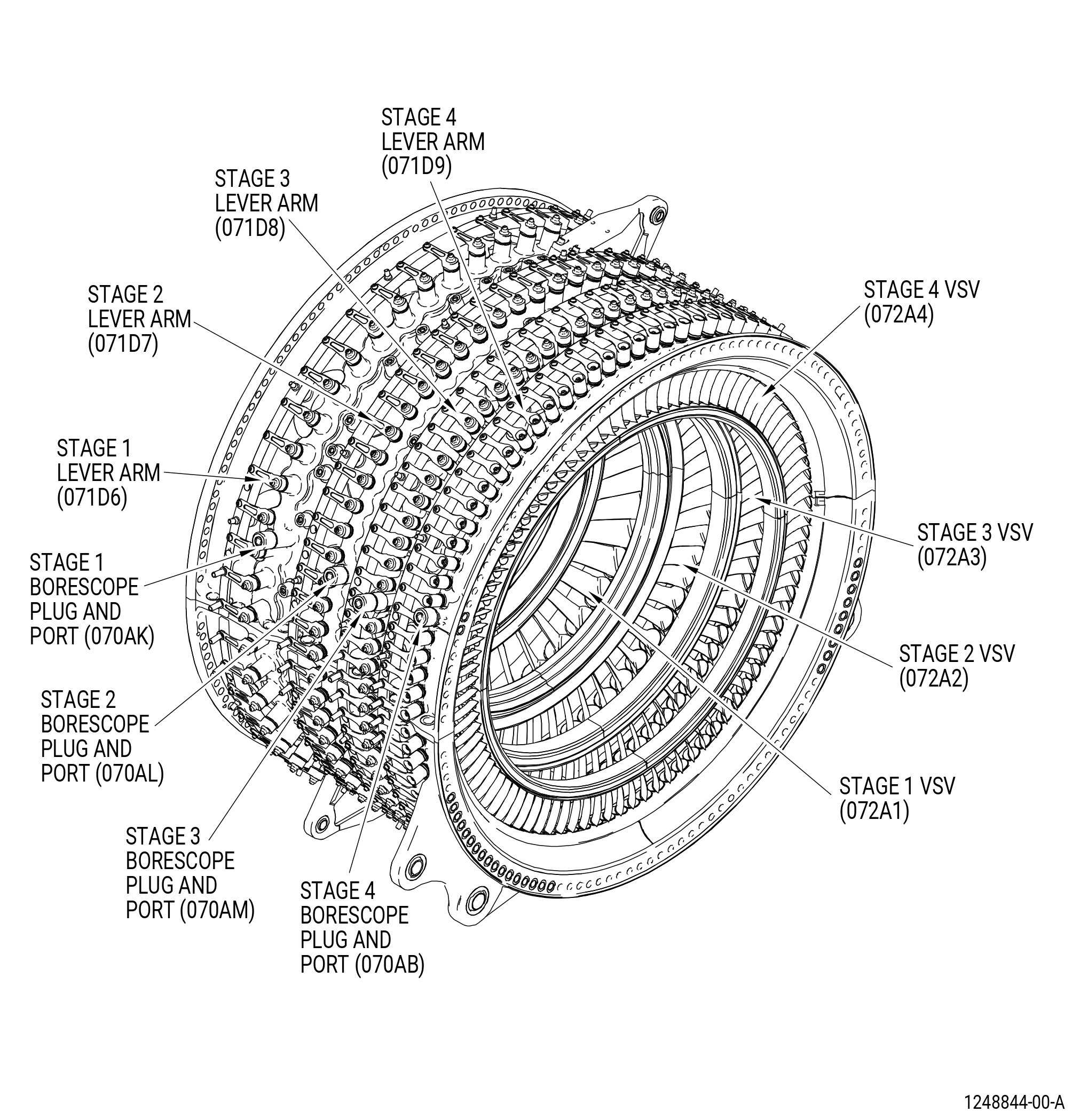
| A. | Do an inspection of the HPC stator forward case assembly (case assembly) (073A0) as follows. Refer to Figure 801. |
| (1) | Cracks in the outer surface (skin): |
| Maximum serviceable limit: |
|
| Repair method: |
|
| Subtask 72-00-32-220-002 |
| (2) | Cracks in the ribs (stage 2 only - between the VSV holes): |
| Maximum serviceable limit: |
|
| Maximum repairable limit: |
|
| Repair method: |
|
| Subtask 72-00-32-220-003 |
| (3) | Cracks in the horizontal and circumferential flanges: |
| Maximum serviceable limit: |
|
| Repair method: |
|
| Subtask 72-00-32-220-004 |
| (4) | Nicks and scratches on the mating surfaces of the horizontal flanges: |
| Maximum serviceable limit: |
|
| Maximum repairable limit: |
|
| Repair method: |
|
| Subtask 72-00-32-220-005 |
| (5) | Nicks and scratches on the mating surfaces of the circumferential flanges: |
| Maximum serviceable limit: |
|
| Maximum repairable limit: |
|
| Repair method: |
|
| Subtask 72-00-32-220-006 |
| (6) | Nicks, pits, scores, and scratches on all surfaces: |
| Maximum serviceable limit: |
|
| Maximum repairable limit: |
|
| Repair method: |
|
| Subtask 72-00-32-220-007 |
| (7) | Discoloration (hot spots) on all surfaces: |
| Maximum serviceable limit: |
|
| Repair method: |
|
| Subtask 72-00-32-220-008 |
| (8) | Rubs and gouges in the flowpath surface: |
| Maximum serviceable limit: |
|
| Maximum repairable limit: |
|
| Repair method: |
|
| Subtask 72-00-32-220-009 |
| (9) | Nicks, dents, and scratches in the flowpath surface: |
| Maximum serviceable limit: |
|
| Maximum repairable limit: |
|
| Repair method: |
|
| Subtask 72-00-32-220-010 |
| (10) | Local scabs (positive metal deposits from the blades) on the flowpath surface: |
| Maximum serviceable limit: |
|
| Maximum repairable limit: |
|
| Repair method: |
|
| Subtask 72-00-32-220-011 |
| (11) | Loose, missing, or damaged insert threads on the mounting pads, bosses, and aft circumferential flange: |
| Maximum serviceable limit: |
|
| Repair method: |
|
| Subtask 72-00-32-220-012 |
| (12) | Damaged threads on the stages 1 thru 4 borescope plugs (070AK, 070AL, 070AM, 070AB) and ports: |
| Maximum serviceable limit: |
|
| Maximum repairable limit: |
|
| Repair method: |
|
| Subtask 72-00-32-220-016 |
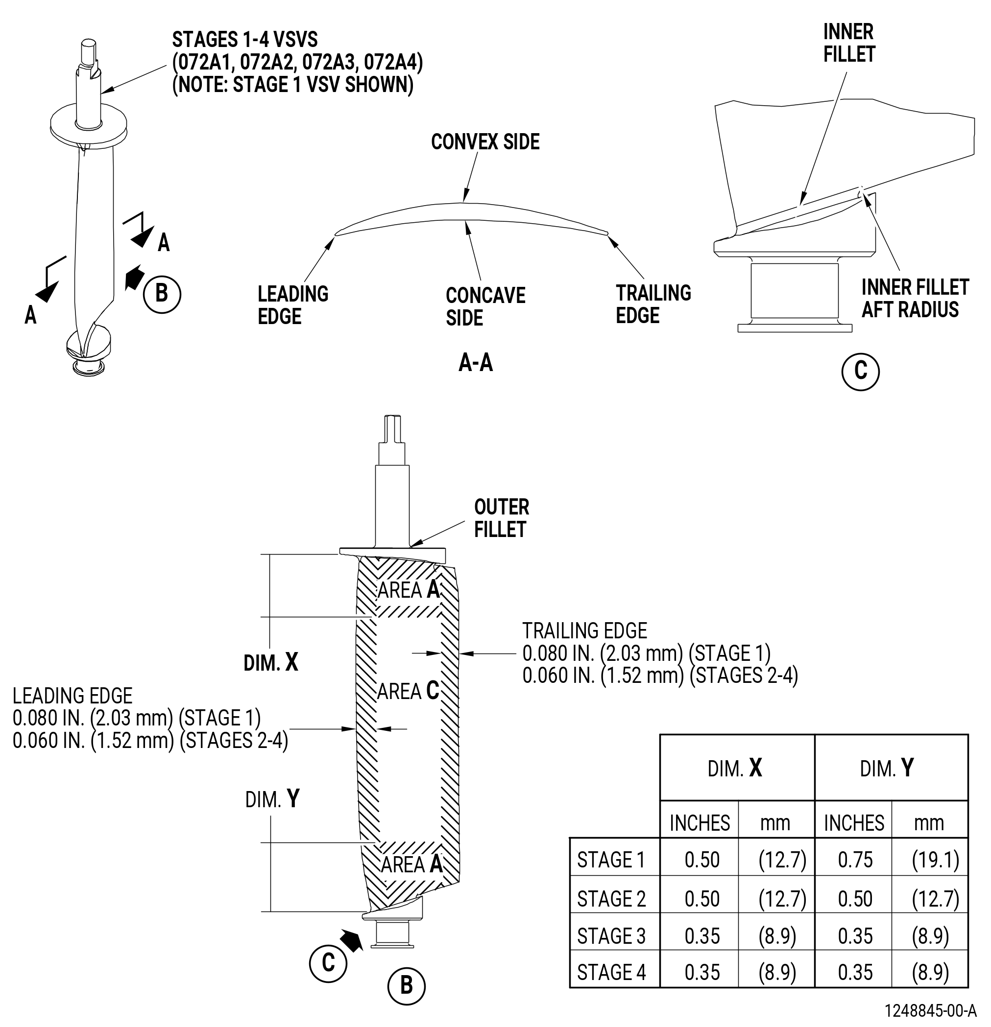
| B. | Do an inspection of area A (critical) of the HPC stages 1 thru 4 variable stator vanes (VSVs) (072A1, 072A2, 072A3, 072A4) as follows. Refer to Figure 802. |
| NOTE: |
|
| NOTE: |
|
| (1) | Nicks, dents, pits, and scratches: |
| Maximum serviceable limit: |
|
| Repair method: |
|
| Subtask 72-00-32-220-017 |
| (2) | Tears and cracks: |
| Maximum serviceable limit: |
|
| Repair method: |
|
| Subtask 72-00-32-220-018 |
| (3) | Transverse scratches in the fillets: |
| Maximum serviceable limit: |
|
| Repair method: |
|
| Subtask 72-00-32-220-019 |
| (4) | Wear that is caused where the shroud touches the VSV: |
| Maximum serviceable limit: |
|
| Repair method: |
|
| Subtask 72-00-32-220-020 |
| C. | Do an inspection of area C (center panel) of each of the stages 1 thru 4 VSVs as follows. Refer to Figure 802. |
| NOTE: |
|
| NOTE: |
|
| (1) | Nicks, dents, and pits: |
| Maximum serviceable limit: |
|
| Repair method: |
|
| Subtask 72-00-32-220-021 |
| (2) | Tears and cracks: |
| Maximum serviceable limit: |
|
| Repair method: |
|
| Subtask 72-00-32-220-022 |
| (3) | Scratches: |
| Maximum serviceable limit: |
|
| Repair method: |
|
| Subtask 72-00-32-220-023 |
| D. | Do an inspection of the leading/trailing edges of each of the stages 1 thru 4 VSVs as follows. Refer to Figure 802. |
| NOTE: |
|
| NOTE: |
|
| (1) | Nicks, dents, and pits: |
| Maximum serviceable limit: |
|
| • |
|
| • |
|
| • |
|
| • |
|
| Maximum repairable limit: |
|
| • |
|
| • |
|
| • |
|
| • |
|
| Repair method: |
|
| Subtask 72-00-32-220-024 |
| (2) | Erosion on the leading edge: |
| Maximum serviceable limit: |
|
| Repair method: |
|
| Subtask 72-00-32-220-025 |
| (3) | Tears and cracks: |
| Maximum serviceable limit: |
|
| Maximum repairable limit: |
|
| • |
|
| • |
|
| • |
|
| • |
|
| Repair method: |
|
| Subtask 72-00-32-220-026 |
| (4) | Deposits: |
| Maximum serviceable limit: |
|
| Maximum repairable limit: |
|
| Repair method: |
|
| Subtask 72-00-32-220-027 |
| (5) | Erosion on the trailing edge: |
| Maximum serviceable limit: |
|
| Repair method: |
|
| Subtask 72-00-32-220-034 |
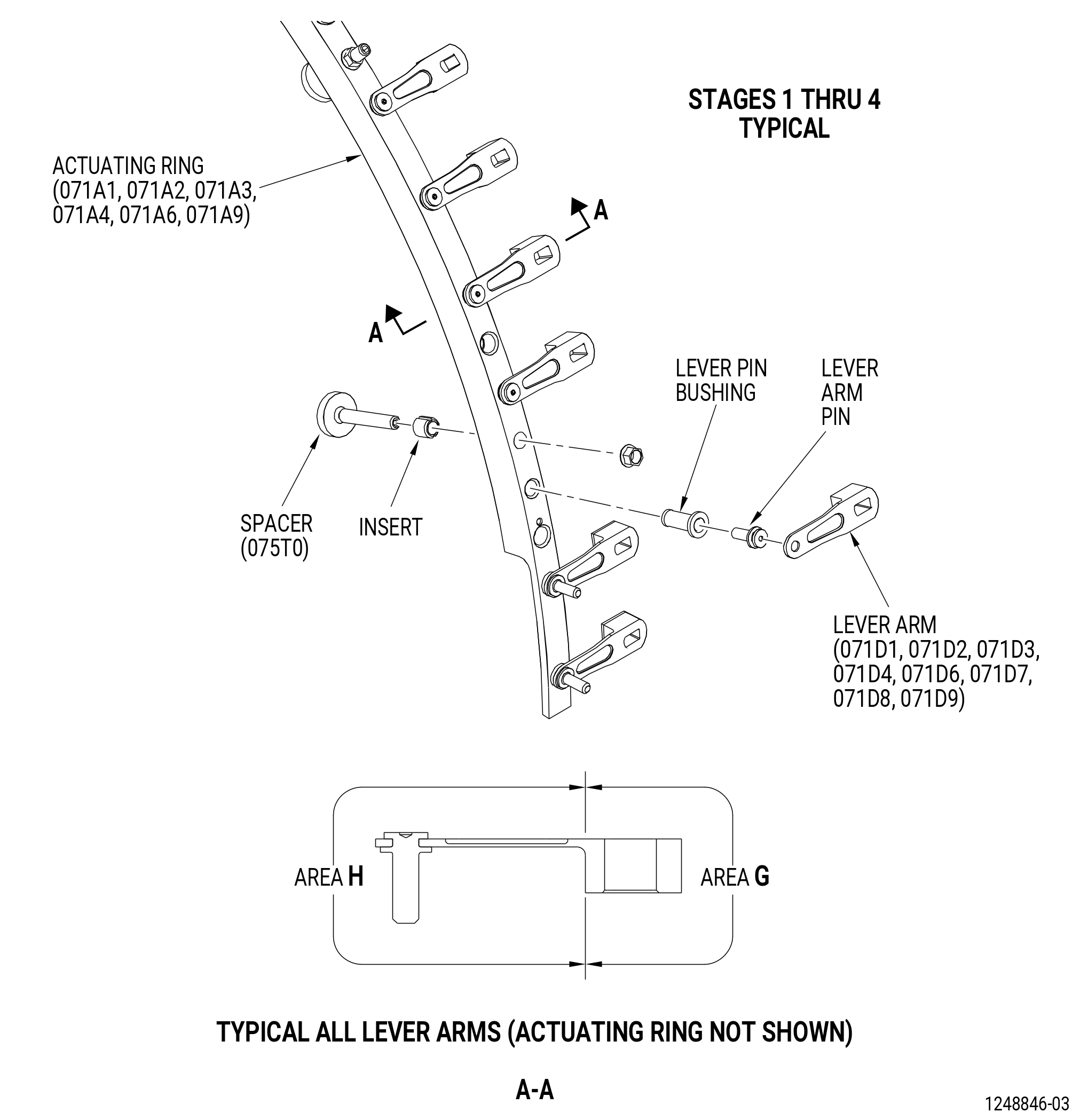
| E. | Do an inspection of all areas of the stages 1 thru 4 VSV lever arms (lever arms) as follows. Refer to Figure 803. |
| • |
|
| • |
|
| • |
|
| • |
|
| (1) | Cracks: |
| Maximum serviceable limit: |
|
| Repair method: |
|
| Subtask 72-00-32-220-035 |
| (2) | Distortion: |
| Maximum serviceable limit: |
|
| Repair method: |
|
| Subtask 72-00-32-220-036 |
| (3) | Nicks, dents, and scratches in area H: |
| Maximum serviceable limit: |
|
| Repair method: |
|
| Subtask 72-00-32-220-037 |
| (4) | Nicks, dents, and scratches in area G: |
| Maximum serviceable limit: |
|
| Maximum repairable limit: |
|
| Repair method: |
|
| Subtask 72-00-32-220-038 |
| F. | Do an inspection of the pins of each lever arm as follows. Refer to Figure 803. |
| (1) | Distortion: |
| Maximum serviceable limit: |
|
| Repair method: |
|
| Subtask 72-00-32-220-046 |
| (2) | Looseness of the heads: |
| Maximum serviceable limit: |
|
| Repair method: |
|
| Subtask 72-00-32-220-047 |
| (3) | Breaks: |
| Maximum serviceable limit: |
|
| Repair method: |
|
| Subtask 72-00-32-220-039 |
| G. | Do an inspection of all areas of the HPC stator stages 1 thru 4 VSV upper and lower actuating rings (actuating rings). Refer to Figure 803. |
| • |
|
| • |
|
| • |
|
| • |
|
| (1) | Cracks: |
| Maximum serviceable limit: |
|
| Repair method: |
|
| Subtask 72-00-32-220-048 |
| (2) | Distortion (twists or bends): |
| Maximum serviceable limit: |
|
| Repair method: |
|
| Subtask 72-00-32-220-049 |
| (3) | Nicks and scratches: |
| Maximum serviceable limit: |
|
| Maximum repairable limit: |
|
| Repair method: |
|
| Subtask 72-00-32-220-050 |
| (4) | Dents: |
| Maximum serviceable limit: |
|
| Repair method: |
|
| Subtask 72-00-32-220-041 |
| H. | Do an inspection of the inserts of each actuating ring as follows. Refer to Figure 803. |
| (1) | Inserts that are broken or worn: |
| Maximum serviceable limit: |
|
| Repair method: |
|
| Subtask 72-00-32-220-042 |
| I. | Do an inspection of the stages 1 thru 4 VSV actuation ring spacers (spacers) (075T0) on the actuating ring as follows. Refer to Figure 803. |
| (1) | Cracks: |
| Maximum serviceable limit: |
|
| Repair method: |
|
| Subtask 72-00-32-220-051 |
| (2) | Distortion: |
| Maximum serviceable limit: |
|
| Repair method: |
|
| Subtask 72-00-32-220-052 |
| (3) | A spacer rub button that is loose in its metallic support: |
| Maximum serviceable limit: |
|
| Repair method: |
|
| Subtask 72-00-32-220-053 |
| (4) | Spacer button wear: |
| Maximum serviceable limit: |
|
| Repair method: |
|
| Subtask 72-00-32-220-043 |
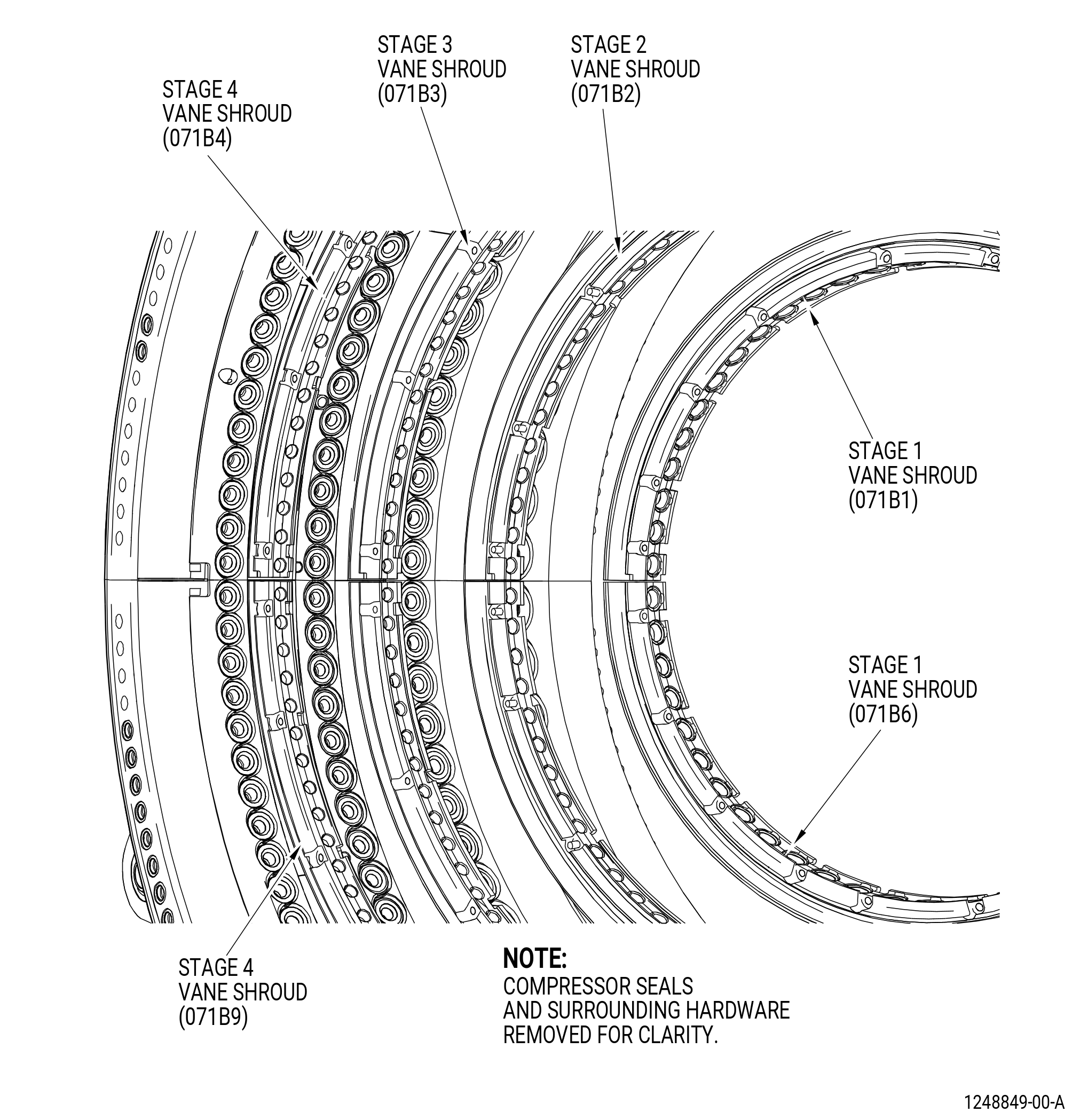
| J. | Do an inspection of the HPC stator stages 1 thru 4 vane shrouds (vane shrouds) as follows. Refer to Figure 801 and Figure 804. |
| • |
|
| • |
|
| • |
|
| • |
|
| (1) | Cracks: |
| Maximum serviceable limit: |
|
| Repair method: |
|
| Subtask 72-00-32-220-054 |
| (2) | Nicks and scratches: |
| Maximum serviceable limit: |
|
| Maximum repairable limit: |
|
| Repair method: |
|
| Subtask 72-00-32-220-055 |
| (3) | Dents: |
| Maximum serviceable limit: |
|
| Maximum repairable limit: |
|
| Repair method: |
|
| Subtask 72-00-32-220-044 |
| K. | Do an inspection of the HPC stator stages 1 and 2 interstage seals (interstage seals) (076A1, 076AA, 076A2, 076AB) as follows. Refer to Figure 805. |
| (1) | Cracks in the backing strip and stop block: |
| Maximum serviceable limit: |
|
| Repair method: |
|
| Subtask 72-00-32-220-058 |
| (2) | Nicks, dents, and scores in the backing strip and stop block: |
| Maximum serviceable limit: |
|
| Repair method: |
|
| Subtask 72-00-32-220-059 |
| (3) | Grooves in the seal land: |
| Maximum serviceable limit: |
|
| Repair method: |
|
| Subtask 72-00-32-220-045 |
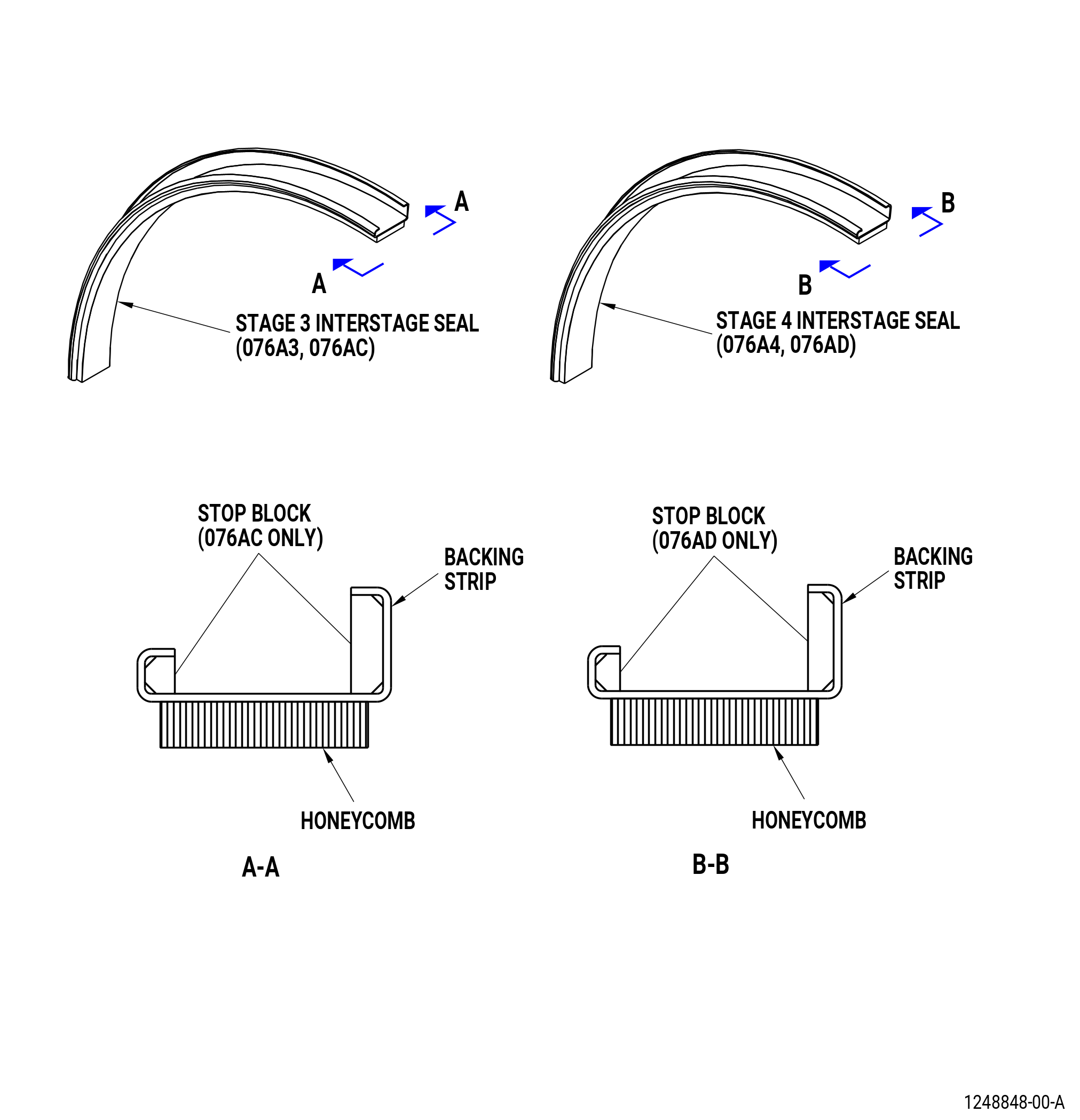
| L. | Do an inspection of the HPC stator stages 3 and 4 interstage seals (interstage seals) (076A3, 076AC, 076A4, 076AD) as follows. Refer to Figure 805. |
| (1) | Cracks in the backing strip and stop block: |
| Maximum serviceable limit: |
|
| Repair method: |
|
| Subtask 72-00-32-220-060 |
| (2) | Grooves in the honeycomb: |
| Maximum serviceable limit: |
|
| Repair method: |
|
| Subtask 72-00-32-220-061 |
| (3) | Damaged cells: |
| Maximum serviceable limit: |
|
| Repair method: |
|
| Subtask 72-00-32-220-070 |
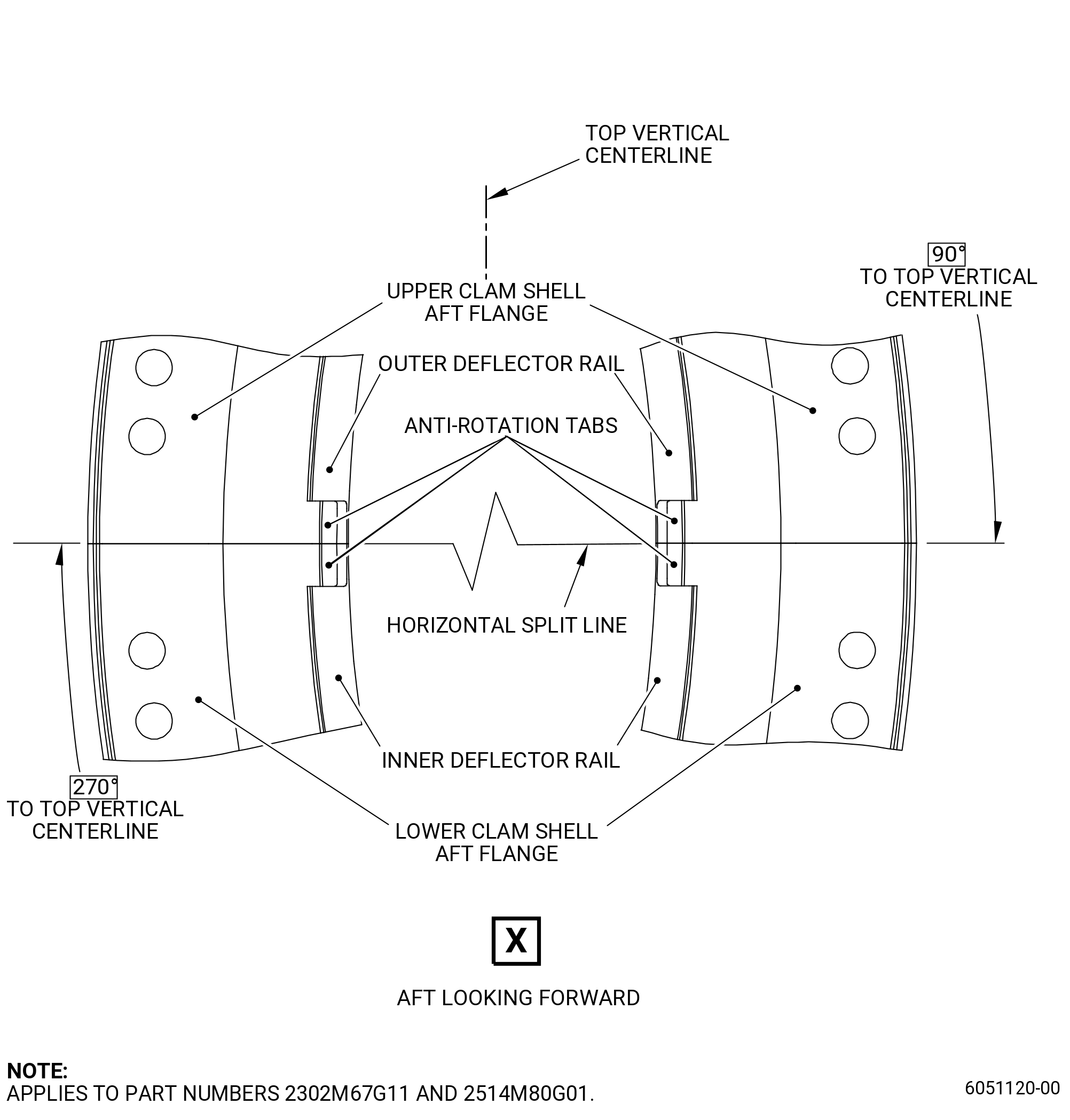
| M. | Do an inspection of the inner stage 4 vane sector tongue (deflector rail) for. Refer to Figure 806. |
| (1) | Fretting and/or wear at the location of contact with the aft cover (deflector) at anti-rotation tab: |
| Maximum serviceable limit: |
|
| Repair method: |
|
| NOTE: |
|
| Subtask 72-00-32-220-072 |
| (2) | Fretting and/or wear at the location of contact with the aft cover (deflector) not at the anti-rotation tab: |
| Maximum serviceable limit: |
|
| Repair method: |
|
| NOTE: |
|
| Subtask 72-00-32-220-071 |
| N. | Do an inspection of the outer stage 4 vane sector tongue (deflector rail) for. Refer to Figure 806. |
| (1) | Fretting and/or wear at the location of contact with the aft cover (deflector) at anti-rotation tab: |
| Maximum serviceable limit: |
|
| Repair method: |
|
| NOTE: |
|
| Subtask 72-00-32-220-073 |
| (2) | Fretting and/or wear at the location of contact with the aft cover (deflector) not at the anti-rotation tab: |
| Maximum serviceable limit: |
|
| Repair method: |
|
| 5 . | Dimensional Inspection |
| Refer to Figure 807. |
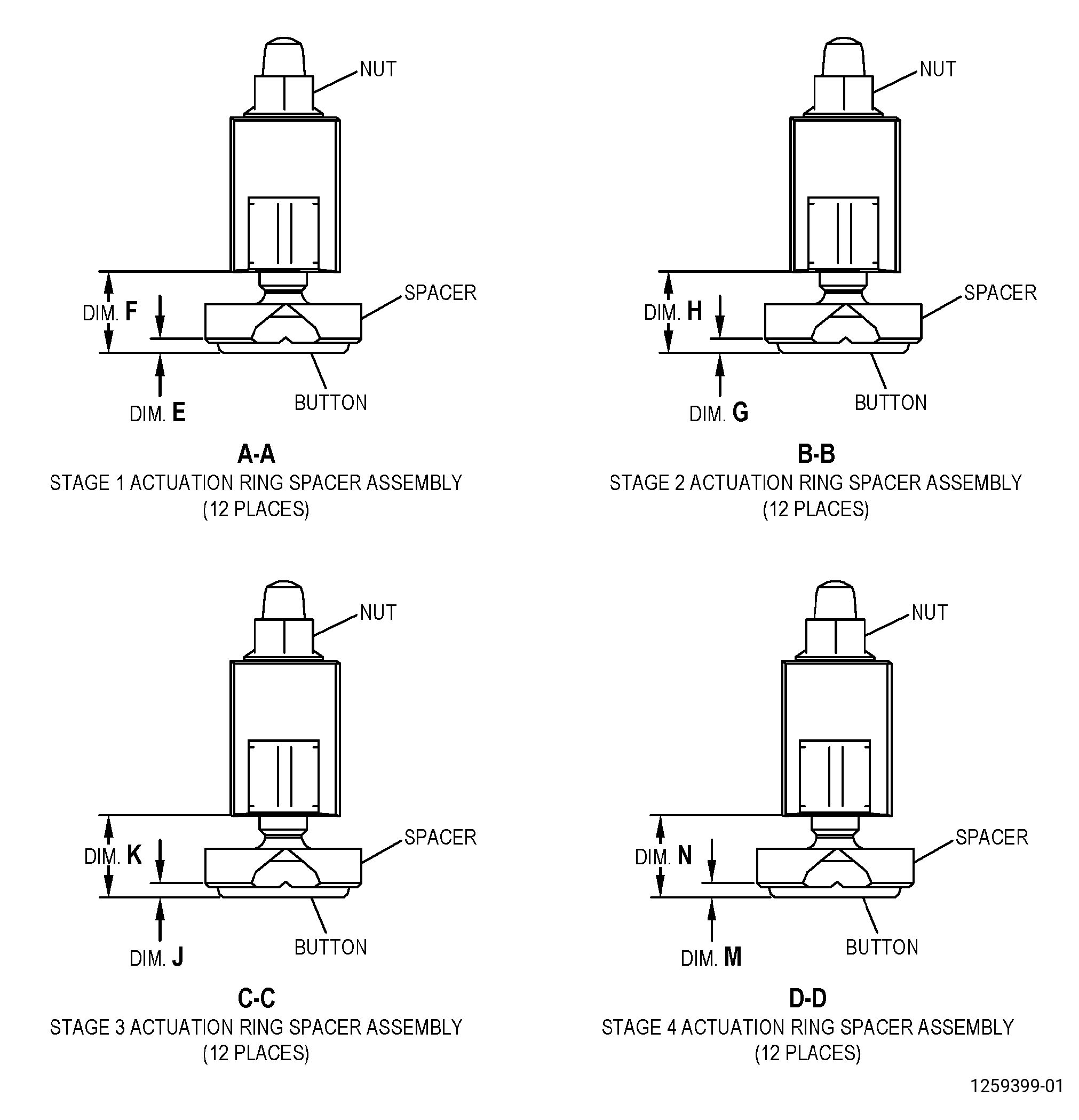
| Subtask 72-00-32-220-062 |
| A. | Do a dimensional inspection of the stage 1 actuation ring spacer assembly as follows: |
| (1) | Dimension E (button): |
| Minimum serviceable limit: |
|
| Repair method: |
|
| Subtask 72-00-32-220-063 |
| (2) | Dimension F: |
| Minimum serviceable limit: |
|
| Maximum serviceable limit: |
|
| Maximum repairable limit: |
|
| Repair method: |
|
| Subtask 72-00-32-220-064 |
| B. | Do an dimensional inspection of the stage 2 actuating ring spacer assembly as follows: |
| (1) | Dimension G (button): |
| Minimum serviceable limit: |
|
| Repair method: |
|
| Subtask 72-00-32-220-065 |
| (2) | Dimension H: |
| Minimum serviceable limit: |
|
| Maximum serviceable limit: |
|
| Maximum repairable limit: |
|
| Repair method: |
|
| Subtask 72-00-32-220-066 |
| C. | Do an dimensional inspection of the stage 3 actuating ring spacer assembly as follows: |
| (1) | Dimension J (button): |
| Minimum serviceable limit: |
|
| Repair method: |
|
| Subtask 72-00-32-220-067 |
| (2) | Dimension K: |
| Minimum serviceable limit: |
|
| Maximum serviceable limit: |
|
| Maximum repairable limit: |
|
| Repair method: |
|
| Subtask 72-00-32-220-068 |
| D. | Do an dimensional inspection of the stage 4 actuating ring spacer assembly as follows: |
| (1) | Dimension M (button): |
| Minimum serviceable limit: |
|
| Repair method: |
|
| Subtask 72-00-32-220-069 |
| (2) | Dimension N: |
| Minimum serviceable limit: |
|
| Maximum serviceable limit: |
|
| Maximum repairable limit: |
|
| Repair method: |
|