| GENX-1B CLEANING,INSPECTION,AND REPAIR MANUAL | Dated: 06/22/2022 | |
| CIR 72-32-05 , REPAIR 001 | ||
| HPC STATOR STAGE 3 INTERSTAGE SEALS - REPAIR - HONEYCOMB REPLACEMENT | ||
| GENX-1B CLEANING,INSPECTION,AND REPAIR MANUAL | Dated: 06/22/2022 | |
| CIR 72-32-05 , REPAIR 001 | ||
| HPC STATOR STAGE 3 INTERSTAGE SEALS - REPAIR - HONEYCOMB REPLACEMENT | ||
| * * * FOR ALL |
| TASK 72-32-05-300-801 |
| 1 . | Honeycomb Replacement. |
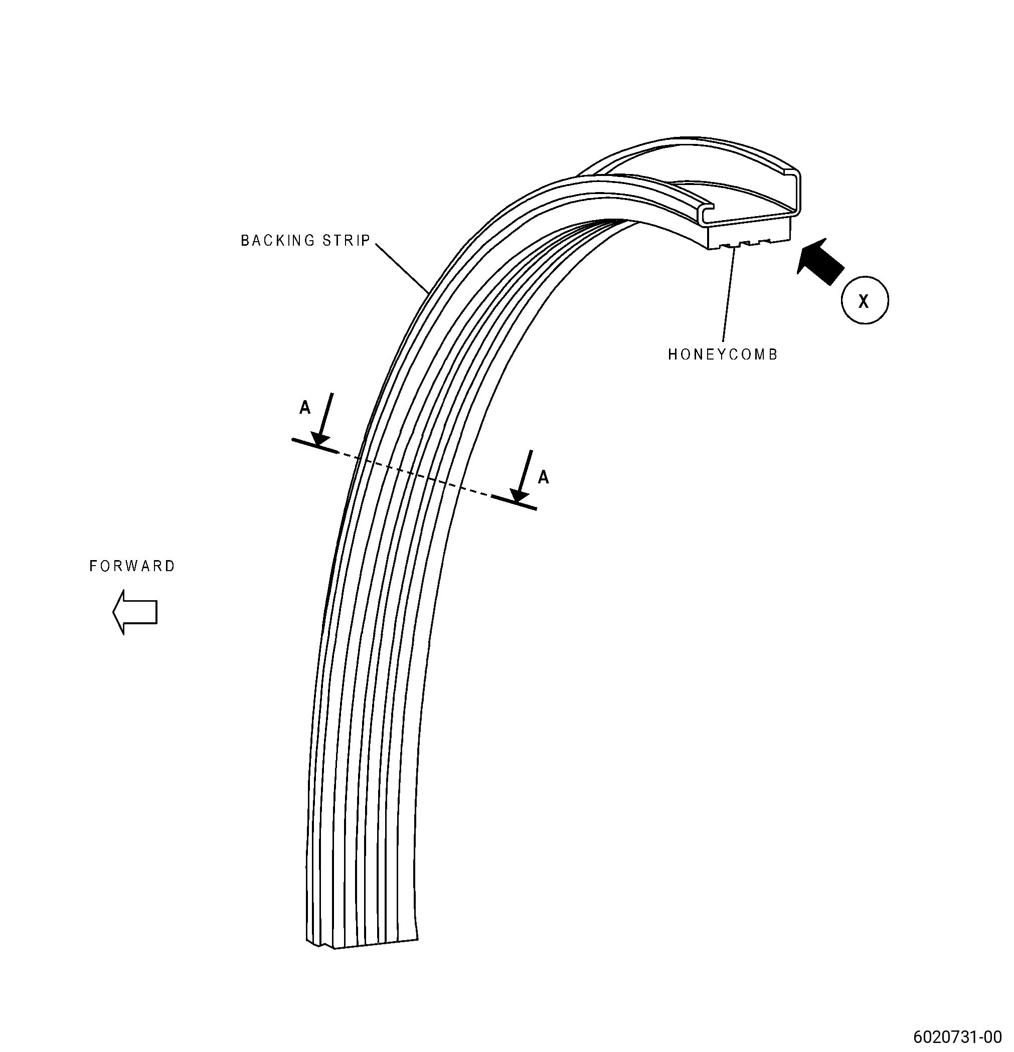
| A. | This procedure gives instructions to repair the HPC stator stage 3 interstage seals (seals) by replacement of worn or damaged honeycomb seal (honeycomb). Refer to Figure 901. |
| B. | The following maximum repairable limits apply to this repair: |
| NOTE: |
|
| (4) | Visual Inspection. |
| (b) | Do an inspection of the honeycomb for: |
| 1 | Grooves: |
| Maximum repairable limit: |
|
| 2 | Damaged or missing cells: |
| Maximum repairable limit: |
|
| 3 | Nicks, dents, pits, gouges, and tears: |
| Maximum repairable limit: |
|
| C. | The subsequent table gives a list of the part numbers that are applicable to this procedure. All part numbers are applicable to all paragraphs unless specified differently. |
|
|||||||||||||||||||||||
| D. | Proprietary/Complex Process Statement. |
| (1) | None. |
| 2 . | Tools, Equipment, and Materials. |
| NOTE: |
|
| A. | Tools and Equipment. |
| (1) | Special Tools. None. |
| (2) | Standard Tools and Equipment. None. |
| (3) | Locally Manufactured Tools. |
|
| B. | Consumable Materials. |
| C. | Referenced Procedures. |
|
| D. | Expendable Parts. None. |
| E. | SPD Information. |
| (1) | Spares Supplied. None. |
| (2) | Protected Spares. None. |
| (3) | Locally Manufactured Spares. |
|
| F. | Special Solutions. None. |
| G. | Test Specimens. None. |
| 3 . | Dimensional Information. |
| Subtask 72-32-05-220-025 |
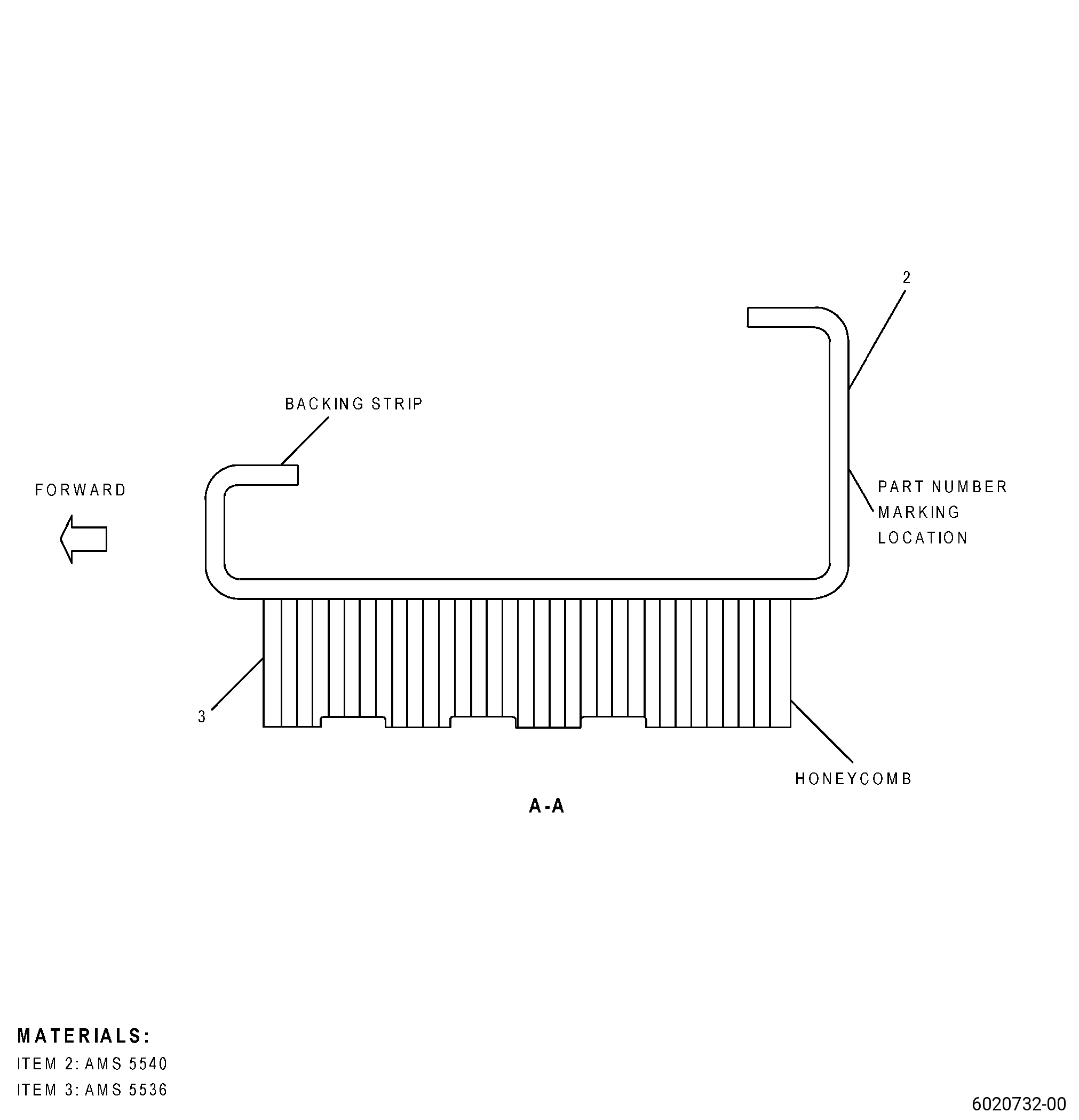
| A. | Refer to Figure 901 for specified dimensions and locations. |
| NOTE: |
|
| NOTE: |
|
| 4 . | Setup Information. |
| Subtask 72-32-05-350-002 |
| A. | Set-up the seal for machining. Refer to Figure 903 as follows: |
| (1) | Restrain Datum A flat to 0.004 inch (0.10 mm) or less. |
| 5 . | Procedure. |
| Subtask 72-32-05-350-003 |
| A. | Alternative Procedure Available. Remove the honeycomb from the seal backing strip. Refer to Figure 901, Figure 902, and as follows: |
| (1) | Hold the backing strip parallel to the belt sander. Remove an equal quantity of honeycomb across the seal width. |
| WARNING: |
|
| CAUTION: |
|
| (2) | Grind the honeycomb. Refer to TASK 70-00-03-800-004 (MACHINING DATA), and as follows: |
| (a) | Grind the honeycomb until you have only honeycomb stubble. |
| (3) | Remove the seal from the grind machine. |
| CAUTION: |
|
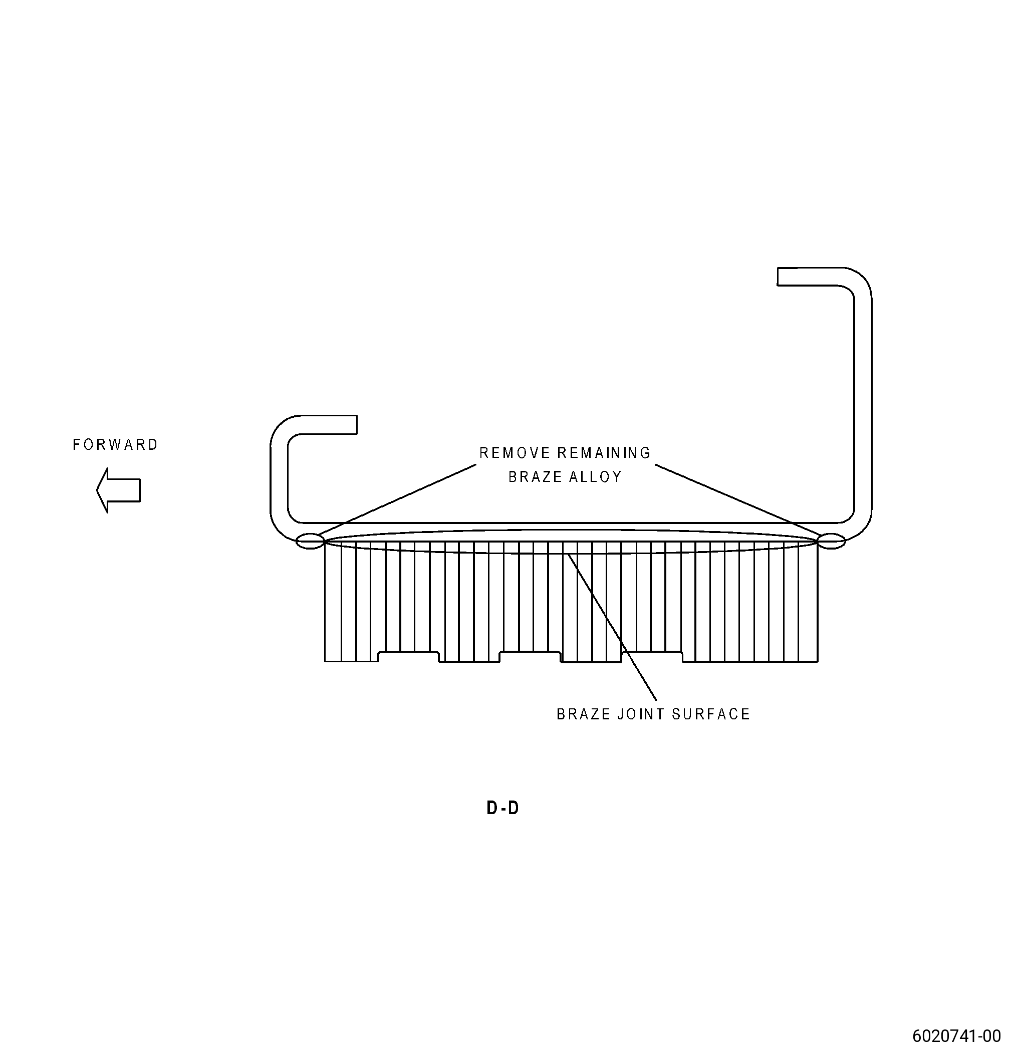
| (4) | Alternative Procedure Available. If necessary, blend the seal backing strip to remove the remaining honeycomb and braze alloy to keep only a witness of the honeycomb pattern on the seal backing strip. Refer to TASK 70-42-00-350-002 (BLENDING AND REMOVAL OF HIGH METAL PROCEDURES), and as follows: |
| (a) | Keep only a witness of the honeycomb pattern on the seal backing strip. |
| (b) | It is not necessary to remove all the braze alloy from the seal backing strip. |
| (c) | Keep machining to a minimum into the backing strip parent material. |
| (4).A. | Alternative Procedure. Grind the seal to remove the remaining honeycomb and braze material from the seal backing strip and as follows: |
| (a) | Use a belt grinder with a 180-320 silicon carbide belt. |
| (b) | Keep only a witness of the honeycomb pattern on the seal backing strip. |
| (c) | It is not necessary to remove all the braze alloy from the backing strip. |
| (d) | Keep machining to a minimum into the backing strip parent material. |
| Subtask 72-32-05-350-010 |
| A.A. | Alternative Procedure. Remove the honeycomb from the seal backing strip. Refer to TASK 70-00-03-800-004 (MACHINING DATA), Figure 901, Figure 902, and as follows: |
| CAUTION: |
|
| (1) | Remove the honeycomb from the backing strip with a vibrating chisel power tool and as follows: |
| (a) | Do not remove parent material. |
| CAUTION: |
|
| (2) | Alternative Procedure Available. Blend the seal as necessary to remove the remaining honeycomb and braze alloy to keep only a witness of the honeycomb pattern on the seal backing strip. Refer to TASK 70-42-00-350-002 (BLENDING AND REMOVAL OF HIGH METAL PROCEDURES), and as follows: |
| (a) | Keep only a witness of the honeycomb pattern on the seal backing strip. |
| (b) | It is not necessary to remove all the braze alloy from the backing strip. |
| (c) | Keep blending to a minimum into the backing strip parent material. |
| (2).A. | Alternative Procedure. Grind the seal to remove the remaining honeycomb and braze material from the seal backing strip and as follows: |
| (a) | Use a belt grinder with a 180-320 silicon carbide belt. |
| (b) | Keep only a witness of the honeycomb pattern on the seal backing strip. |
| (c) | It is not necessary to remove all the braze alloy from the backing strip. |
| (d) | Keep grinding to a minimum into the backing strip parent material. |
| Subtask 72-32-05-220-026 |
| B. | Do an inspection of the seal backing strip in the area where the honeycomb was removed. Refer to Figure 901, Figure 903, and as follows: |
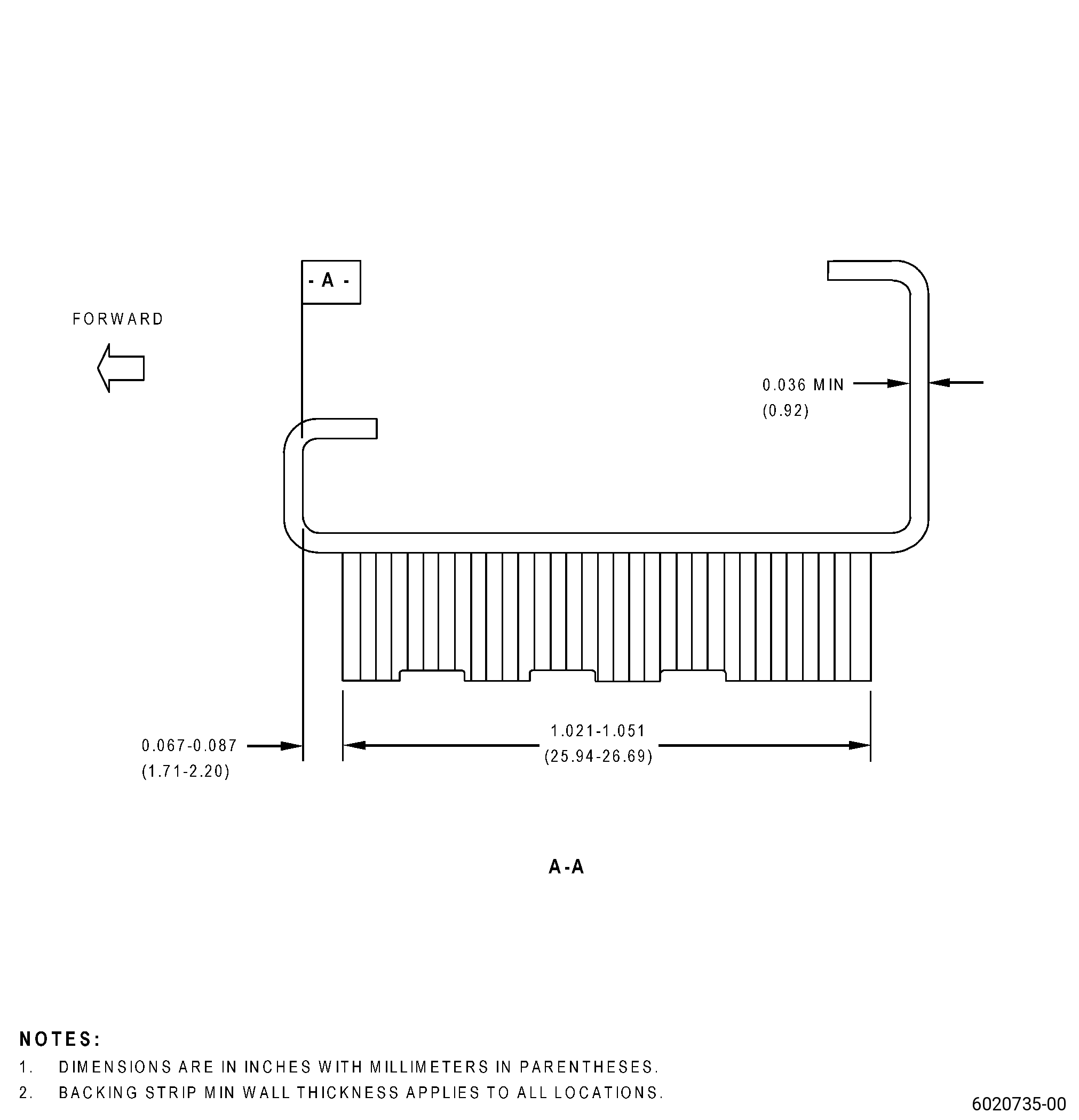
| (1) | Measure the thickness of the backing strip at a location where the honeycomb and the braze alloy were fully removed and as follows: |
| (a) | The seal backing strip must have a minimum serviceable thickness of 0.036 inch (0.92 mm). |
| (b) | If the seal backing strip thickness is less than the minimum serviceable limit, the seal is not repairable with this repair procedure. Replace the seal. |
| (c) | If the seal backing strip does not have areas of exposed parent material, it is not necessary to measure its thickness. |
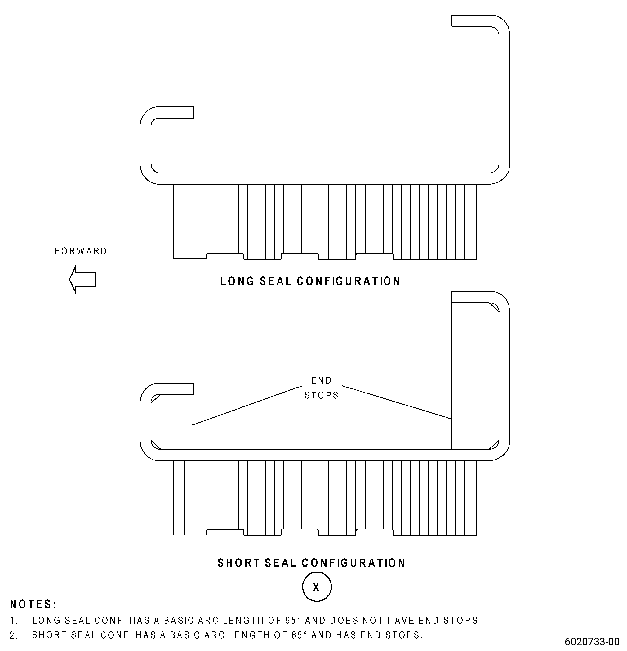
| (2) | Do an inspection of the seal backing strip contour. Refer to Figure 901, Figure 904, and as follows: |
| (a) | If necessary, make the contour gage. Refer to TASK 70-31-06-220-001 (MACHINED FEATURES SHOP-RUN TOLERANCES). |
| (b) | In free state, the contour gage must manually pass freely through the full arc length of the long seal configuration. |
| (c) | In free state, the contour gage must manually pass freely through the arc length of the short seal configuration until the contour gage touches the end stops. |
| (d) | Make sure that the backing strip goes freely through the contour gage. |
| Subtask 72-32-05-350-004 |
| C. | If the backing strip does not go freely through the contour gage, cold-work the backing strip to the correct contour. Refer to TASK 70-47-05-350-023 (COLD-WORKING REPAIR), and as follows: |
| (1) | After you cold-work the seal, do an inspection of the backing strip contour. Refer to Subtask 72-32-05-220-026 (paragraph 5.B.(2)). |
| Subtask 72-32-05-220-036 |
| D. | Measure the backing strip arc length. Refer to Figure 901, Figure 905, and as follows: |
| (1) | Identify the parts that are shorter than the minimum serviceable arc length for weld build-up. |
| Subtask 72-32-05-310-001 |
| E. | If necessary, weld the backing strips that are shorter than the minimum serviceable arc length as follows: |
| CAUTION: |
|
| (1) | Do a weld build-up of the worn end of the backing strip to repair the arc length. Refer to TASK 70-41-00-310-001 (WELDING AND BRAZING PRACTICES), and as follows: |
| (a) | Use C06-050 weld wire. |
| (b) | Weld additional stock to the worn backing strip end. |
| Subtask 72-32-05-350-005 |
| F. | Blend the additional weld stock inner diameter (ID) and outer diameter (OD). Refer to TASK 70-42-00-350-002 (BLENDING AND REMOVAL OF HIGH METAL PROCEDURES), Figure 901, Figure 903, and as follows: |
| (1) | Blend the additional weld stock ID and OD smooth with the backing strip ID and OD surfaces only, and as follows: |
| (a) | Do not remove backing parent material. |
| (b) | The weld areas can protrude 0.001 to 0.005 inch (0.03 to 0.12 mm) above the adjacent parent material surface areas. |
| (2) | Do not blend the end of the additional weld stock to repair the backing strip arc length. The arc length will be repaired later in this repair. |
| (3) | Polish the additional weld stock ID and OD surfaces with a Scotch Brite wheel. |
| (4) | Measure the backing strip thickness in the blend/polish area to make sure that it's equal to or more than the minimum serviceable limit. |
| Subtask 72-32-05-110-009 |
| WARNING: |
|
| G. | Clean the seal backing strip. Refer to TASK 70-21-00-110-051 (CHEMICAL CLEANING), TASK 70-21-23-110-053 (CLEANING METHOD NO. 23 - HAND-WIPE DEGREASING), and as follows: |
| (1) | Alternative Procedure Available. Use C04-003 acetone to clean the mating surface of the backing strip and the replacement honeycomb. |
| (1).A. | Alternative Procedure. Use C04-035 isopropyl alcohol to clean the mating surface of the backing strip and the replacement honeycomb. |
| Subtask 72-32-05-110-010 |
| H. | Etch the seal backing strip OD in the repair areas. Refer to TASK 70-24-00-110-033 (ETCHING PROCEDURES FOR FLUORESCENT-PENETRANT INSPECTION), TASK 70-24-01-110-034 (SWAB ETCHING PROCEDURE), and as follows: |
| (1) | Use Class C etchant. |
| Subtask 72-32-05-230-005 |
| I. | Do an inspection of the seal backing strip OD in the repair area. Refer to TASK 70-32-00-200-002 (INDIRECT INSPECTION METHODS), TASK 70-32-03-230-002 (SPOT-FLUORESCENT-PENETRANT INSPECTION), and as follows: |
| (1) | Use Class A penetrant. |
| (2) | Use Class A acceptability limits. |
| NOTE: |
|
| Subtask 72-32-05-220-027 |
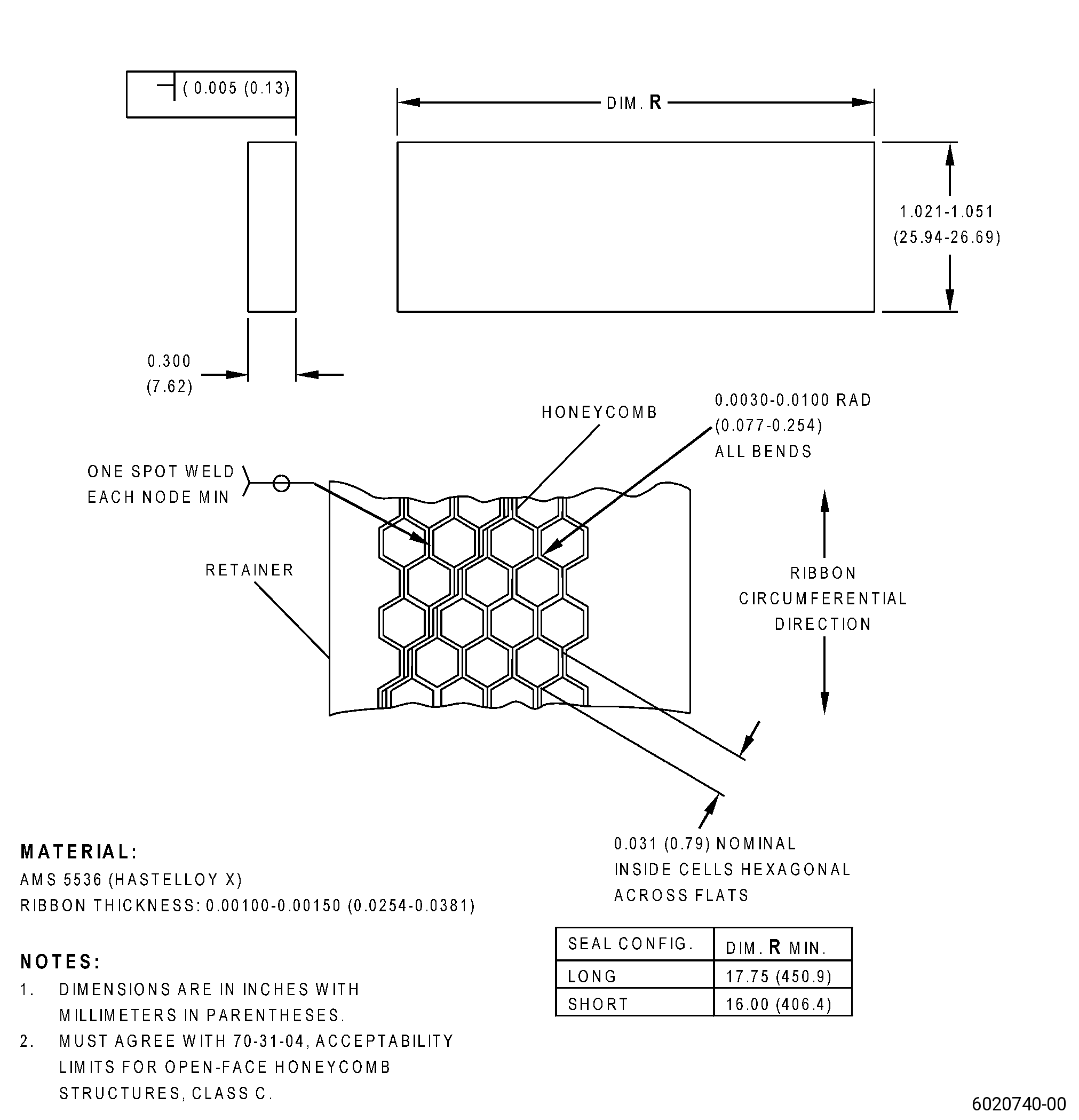
| J. | Make the replacement honeycomb. Refer to TASK 70-31-04-220-001 (ACCEPTABILITY LIMITS FOR AS-MANUFACTURED OPEN-FACE HONEYCOMB), Figure 906, and as follows: |
| (1) | Use Class C limits. |
| Subtask 72-32-70-160-004 |
| WARNING: |
|
| CAUTION: |
|
| K. | Alternative Procedure Available. Clean the seal backing strip and the replacement honeycomb. Refer to TASK 70-21-00-110-051 (CHEMICAL CLEANING), TASK 70-21-22-110-801 (CLEANING METHOD NO. 22 - LIGHT DUTY AQUEOUS CLEANING), and as follows: |
| (1) | Use Method 1. |
| Subtask 72-32-70-160-005 |
| K.A. | Alternative Procedure. Clean the seal backing strip and the replacement honeycomb. Refer to TASK 70-21-00-110-051 (CHEMICAL CLEANING), and TASK 70-21-02-110-002 (CLEANING METHOD NO. 2 - VAPOR DEGREASING). |
| Subtask 72-32-05-160-006 |
| WARNING: |
|
| K.B. | Alternative Procedure. Clean the seal backing strip and replacement honeycomb. Refer to TASK 70-21-00-110-051 (CHEMICAL CLEANING), TASK 70-21-23-110-053 (CLEANING METHOD NO. 23 - HAND-WIPE DEGREASING), and as follows: |
| (1) | Alternative Procedure Available. Use C04-003 acetone to clean the mating surface of the seal backing strip and the replacement honeycomb. |
| (1).A. | Alternative Procedure. Use C04-035 isopropyl alcohol to clean the mating surface of the seal backing strip and the replacement honeycomb. |
| Subtask 72-32-05-330-001 |
| L. | Alternative Procedure Available. Optional Procedure. Nickel-plate the backing strip surface at the honeycomb area. Refer to TASK 70-45-03-330-004 (SELECTIVE CONTACT PLATING), AMS 2403 - Plating, Nickel, General Purpose, Figure 903, and as follows: |
| NOTE: |
|
| (1) | Nickel plate thickness must be 0.00016 to 0.00031 inch (0.0041 to 0.0078 mm). |
| Subtask 72-32-05-120-002 |
| WARNING: |
|
| L.A. | Alternative Procedure. Optional Procedure. Nicrobraze-blast the backing strip surface at the honeycomb area. Refer to TASK 70-21-04-120-001 (CLEANING METHOD NO. 4 - DRY ABRASIVE BLAST CLEANING), Figure 903, and as follows: |
| NOTE: |
|
| (1) | Use C06-028 nichrome base blasting grit. |
| (2) | Use an air pressure of 40-60 psi (276-414 kPa). |
| (3) | Keep the nozzle 6.0-8.0 inches (153-203 mm) from the surface. |
| Subtask 72-32-05-310-002 |
| M. | If braze tape will be used, apply braze alloy (AMS 4777) in tape form with an approximate thickness of 0.020 to 0.030 inch (0.51 to 0.76 mm) to the outer diameter of the replacement honeycomb as follows: |
| (1) | If necessary, make a coupon to simulate the brazing process of the seal to the replacement honeycomb and as follows: |
| NOTE: |
|
| (a) | Find the thickness of braze alloy tape that will get the best brazing results for the honeycomb. |
| (2) | Apply the braze alloy (AMS 4777) in tape form to the outer diameter of the replacement honeycomb. |
| (3) | Use a scraper to remove all unwanted braze alloy from the outer diameter of the replacement honeycomb. |
| Subtask 72-32-05-310-003 |
| CAUTION: |
|
| CAUTION: |
|
| CAUTION: |
|
| N. | Resistance tack-weld the replacement honeycomb to the seal backing strip. Refer to TASK 70-41-00-310-001 (WELDING AND BRAZING PRACTICES), TASK 70-41-04-310-005 (RESISTANCE WELDING - SPOT, SEAM, AND PROJECTION), Figure 901, Figure 908, and as follows: |
| (1) | Put the replacement honeycomb in the correct location on the backing strip and as follows: |
| (a) | The replacement honeycomb must extend more than the two circumferential ends of the seal backing strip. The honeycomb ends will be machined flush with the ends of the seal backing strip later in the repair process. |
| CAUTION: |
|
| (2) | Adjust the resistance tack-weld parameters to get a satisfactory weld between the replacement honeycomb and the seal backing strip, and as follows: |
| Subtask 72-32-05-220-028 |
| (a) | Do a visual inspection of the tack welds to make sure that the honeycomb is correctly attached to the seal backing strip. |
| (b) | Do not burn the honeycomb. |
| (c) | If you find burn marks, make sure that they are sufficiently shallow to remove them during the final machining procedure. |
| Subtask 72-32-05-310-004 |
| (3) | Align the electrodes with the approximate center of the replacement honeycomb and make a tack weld. |
| (4) | Continue to make tack welds until you attach the replacement honeycomb along the full length of the seal backing strip. |
| Subtask 72-32-05-220-029 |
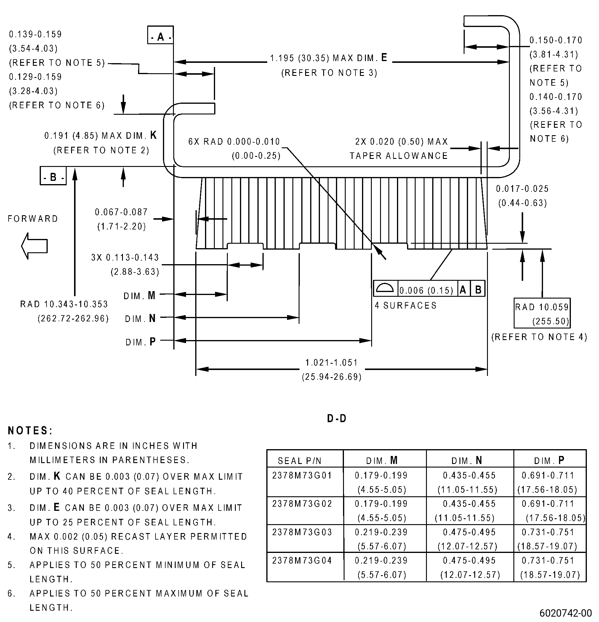
| O. | Do a dimensional inspection of the seal. Refer to Figure 903. |
| Subtask 72-32-05-220-030 |
| P. | Do a visual inspection of the seal as follows: |
| (1) | The replacement honeycomb must be tightly attached to the seal backing strip as follows: |
| (a) | The space between the replacement honeycomb and the seal backing strip must be 0.000 to 0.005 inch (0.00 to 0.12 mm) maximum. |
| (2) | Examine the replacement honeycomb for open nodes as follows: |
| (a) | Open nodes are not permitted. |
| (b) | If necessary, use a tweezer to close all open nodes. |
| (3) | Examine the electrical ground areas for burns and pits as follows: |
| (a) | Burns are not permitted. |
| (b) | If you find pits, use the acceptability limits that follow: |
| 1 | Pits 0.005 inch (0.12 mm) maximum in depth are permitted. |
| 2 | Pits 0.030 inch (0.76 mm) maximum in diameter are permitted. |
| Subtask 72-32-05-350-006 |
| (4) | If necessary, blend the electrical ground areas to remove pits. Refer to TASK 70-42-00-350-002 (BLENDING AND REMOVAL OF HIGH METAL PROCEDURES) and as follows: |
| (a) | Blend pits that are in the limits in Subtask 72-32-05-220-030 (paragraph 5.P.(3)(b)) only. |
| Subtask 72-32-05-310-005 |
| WARNING: |
|
| Q. | Prepare the seal for brazing. Refer to TASK 70-41-00-310-001 (WELDING AND BRAZING PRACTICES), TASK 70-41-03-310-004 (HIGH TEMPERATURE FURNACE BRAZE), and as follows: |
| (1) | If braze alloy (AMS 4777) in tape form was used when tack welding the honeycomb, go to Subtask 72-32-05-310-005 (paragraph 5.Q.(7)). |
| (2) | Apply C06-062 braze alloy powder equally in the honeycomb cells. Make sure that there is sufficient C06-062 braze alloy powder at the bottom of each cell. |
| (3) | Use a high intensity light to examine the bottom of the cells to make sure that sufficient C06-062 braze alloy powder is in each of the cells. |
| (4) | If necessary, remove unwanted braze powder with a C10-108 brush. |
| WARNING: |
|
| CAUTION: |
|
| (5) | Lightly spray C01-034 acrylic binder into the cells and let dry. Use a spray procedure. |
| NOTE: |
|
| (6) | Mix 85 to 90 percent of C06-062 braze alloy powder and 10 to 15 percent in weight of C06-019 braze binder until it becomes a slurry. |
| (7) | Apply the slurry along the full length of the two sides of the honeycomb making a fillet. |
| WARNING: |
|
| (8) | Apply a layer of approximate 0.005 to 0.015 inch (0.13 to 0.38 mm) in thickness of C10-020 braze stop-off at the forward edge and the aft edge, and around the axial edges of the replacement honeycomb on the backing strip. |
| NOTE: |
|
| Subtask 72-32-05-310-006 |
| R. | Braze the replacement honeycomb to the backing strip. Refer to TASK 70-41-00-310-001 (WELDING AND BRAZING PRACTICES), TASK 70-41-03-310-004 (HIGH TEMPERATURE FURNACE BRAZE), and as follows: |
| (1) | Put the load thermocouples on the seal and as follows: |
| (a) | Use quantity and location requirements of the load thermocouples as specified in TASK 70-41-03-310-004 (HIGH TEMPERATURE FURNACE BRAZE). |
| (2) | If necessary, use a locally made holding fixture to keep the seal shape. |
| (3) | Put the seal in the furnace. |
| Subtask 72-32-05-310-007 |
| (4) | Alternative Procedure Available. Braze the seal in a vacuum furnace with a vacuum of 1x10⁻³ torr (0.13 Pa) or better. |
| Subtask 72-32-05-310-008 |
| (4).A. | Alternative Procedure. Braze the seals in a hydrogen furnace at a dew point of -60°F (-51°C) or better. |
| Subtask 72-32-05-310-009 |
| (5) | Increase the temperature of the seal to a range of 1700 to 1800°F (927 to 982°C) and hold the temperature for 10 to 15 minutes. |
| NOTE: |
|
| (6) | Increase the temperature of the seal at a maximum rate of 35°F (19°C) for each minute to 1875 to 1925°F (1024 to 1052°C) and hold the temperature for 5 minutes maximum. |
| (7) | Decrease the temperature of the seal to 1700 to 1800°F (927 to 982°C) at a maximum rate of 35°F (19°C) for each minute and hold the temperature for 15 minutes maximum. |
| CAUTION: |
|
| (8) | Decrease the temperature of the seal to 1000°F (538°C) in 30 minutes or less in vacuum or inert gas atmosphere. |
| NOTE: |
|
| (9) | Decrease the temperature of the seal to room temperature. |
| WARNING: |
|
| (10) | Remove the seal from the furnace. |
| Subtask 72-32-05-220-031 |
| S. | Alternative Procedure Available. Do an inspection of the seal. Refer to TASK 70-33-00-999-001 (SPECIAL INSPECTION PROCEDURES), TASK 70-33-02-220-005 (CAPILLARY INSPECTION OF OPEN FACE HONEYCOMB STRUCTURES). |
| Subtask 72-32-05-220-032 |
| S.A. | Alternative Procedure. Use a video microscope to do an inspection of the seal as follows: |
| (1) | Use minimum 10X magnification. |
| (2) | The honeycomb must be fully bonded to the seal backing strip in 80 percent of the total area. |
| (3) | The total areas of the cells in an unbonded area must not be more than 0.25 inch x 0.25 inch (6.4 mm x 6.4 mm) or 0.06 sq inch (38.7 sq mm). |
| (4) | Unbonded areas must not be more than one-third of the total width of the honeycomb. |
| (5) | A maximum of five unbonded areas of 0.06 sq inch (38.7 sq mm) are permitted. |
| (6) | A maximum of two 0.06 sq inch (38.7 sq mm) unbonded areas at the edge of honeycomb are permitted. |
| (7) | Unbonded areas must be separated a minimum of 0.5 inch (13 mm). |
| (8) | A pair of cells with the same unbonded wall must not be interpreted as an unbonded area. |
| (9) | The honeycomb core must be bonded at 90 percent of its nodes. |
| (10) | Less than 10 percent of the cell height must be filled with braze material. |
| (11) | The honeycomb cells can have a maximum of three adjacent cells plugged with braze alloy if the distance to a different cluster or string is a minimum of 3.0 inches (77 mm) circumferentially or 0.20 inch (5.0 mm) axially. |
| Subtask 72-32-05-320-001 |
| T. | If necessary, machine the seal to remove remaining braze alloy from the honeycomb cells. Refer to TASK 70-00-03-800-004 (MACHINING DATA), and as follows: |
| (1) | Not more than two percent of the cells in a circumferential row can have remaining braze alloy removed. |
| Subtask 72-32-05-320-002 |
| (2) | Alternative Procedure Available. Use a jeweler's drill to remove remaining braze alloy. |
| Subtask 72-32-05-320-003 |
| (2).A. | Alternative Procedure. Use an electrical discharge machining (EDM) to remove remaining braze alloy and as follows: |
| (a) | Maximum intergranular attack permitted is 0.0025 inch (0.063 mm). |
| (b) | Maximum microcracks permitted is 0.0025 inch (0.063 mm). |
| (c) | Maximum continuous recast permitted is 0.0025 inch (0.063 mm). |
| (d) | Maximum local recast permitted is 0.0030 inch (0.076 mm). |
| Subtask 72-32-05-350-007 |
| U. | Blend the seal to remove all the unwanted braze alloy in the area adjacent to the replacement honeycomb. Refer to TASK 70-42-00-350-002 (BLENDING AND REMOVAL OF HIGH METAL PROCEDURES), Figure 907, and as follows: |
| (1) | Use a Scotch Brite wheel to remove unwanted braze material. |
| Subtask 72-32-05-350-008 |
| WARNING: |
|
| CAUTION: |
|
| V. | Machine the seal to remove unwanted replacement honeycomb and weld build-up at one end of the backing strip. Refer to TASK 70-00-03-800-004 (MACHINING DATA), Figure 905, and as follows: |
| (1) | If there is weld build-up at one end of the seal backing strip, grind the weld build-up to repair the backing strip arc length. |
| (2) | Use a cutoff wheel or belt grinder to cut the replacement honeycomb flush to 0.000 to 0.001 inch (0.00 to 0.02 mm) of the ends of the seal backing strip. |
| (3) | Remove all burrs. |
| Subtask 72-32-05-220-033 |
| W. | Do an inspection of the seal contour. Refer to Figure 901, Figure 904, and as follows: |
| (1) | In free state, the contour gage must pass freely manually through the full arc length of the long seal configuration. |
| (2) | In free state, the contour gage must pass freely manually through the arc length of the short seal configuration until the contour gage touches the end stops. |
| (3) | Make sure that the backing strip goes freely through the contour gage. |
| Subtask 72-32-05-350-009 |
| X. | If the seal does not go freely through the contour gage, cold-work the seal to the correct contour. Refer to TASK 70-47-05-350-023 (COLD-WORKING REPAIR), and as follows: |
| (1) | After you cold-work the seal, do an inspection of the seal contour again. Refer to Subtask 72-32-05-220-033 (paragraph 5.W.). |
| Subtask 72-32-05-320-004 |
| Y. | Alternative Procedure Available. Machine the honeycomb seal to the finish dimensions. Refer to TASK 70-00-03-800-004 (MACHINING DATA), Figure 908, and as follows: |
| (1) | Set-up the seal for machining. Refer to Subtask 72-32-05-350-002 (paragraph 4.A.). |
| (2) | Machine the honeycomb seal diameter. |
| (3) | Remove burrs from the seal with a C10-097 wire brush. |
| Subtask 72-32-05-320-005 |
| Y.A. | Alternative Procedure. EDM the replacement honeycomb to the finish dimensions. Refer to TASK 70-00-03-800-004 (MACHINING DATA), Figure 908, and as follows: |
| (1) | Set-up the seal for machining. Refer to Subtask 72-32-05-350-002 (paragraph 4.A.). |
| Subtask 72-32-05-220-034 |
| (2) | Do an inspection of the honeycomb. Refer to TASK 70-31-05-220-001 (ENGINE PART SURFACE INTEGRITY ACCEPTABILITY LIMITS FOR NONTRADITIONAL MACHINED SURFACES), and as follows: |
| (a) | Use Class H limits. |
| (b) | The maximum recast layer can be 0.002 inch (0.05 mm). |
| Subtask 72-32-05-160-007 |
| Z. | Clean the seal. Refer to TASK 72-32-05-100-801 (72-32-05-100-801, CLEANING 001). |
| Subtask 72-32-05-220-035 |
| AA. | Do an inspection of the seal as follows: |
| (1) | Measure the backing strip arc length. Refer to Figure 905 and as follows: |
| (a) | It will be necessary to repair again the parts that are shorter than the minimum serviceable arc length. Go to Subtask 72-32-05-350-003 (paragraph 5.A.). |
| (2) | Do a dimensional inspection of the seal. Refer to Figure 908 and as follows: |
| (a) | With datum B restrained to the dimensional tolerance and datum A restrained flat to 0.004 inch (0.10 mm) or less, all dimensions must agree. |