| GENX-1B CLEANING,INSPECTION,AND REPAIR MANUAL | Dated: 07/24/2024 | |
| CIR 72-32-06 , REPAIR 001 | ||
| HPC STATOR STAGE 4 INTERSTAGE SEALS - REPAIR - HONEYCOMB REPLACEMENT | ||
| GENX-1B CLEANING,INSPECTION,AND REPAIR MANUAL | Dated: 07/24/2024 | |
| CIR 72-32-06 , REPAIR 001 | ||
| HPC STATOR STAGE 4 INTERSTAGE SEALS - REPAIR - HONEYCOMB REPLACEMENT | ||
| * * * FOR ALL |
| TASK 72-32-06-300-801 |
| 1 . | Honeycomb Replacement. |
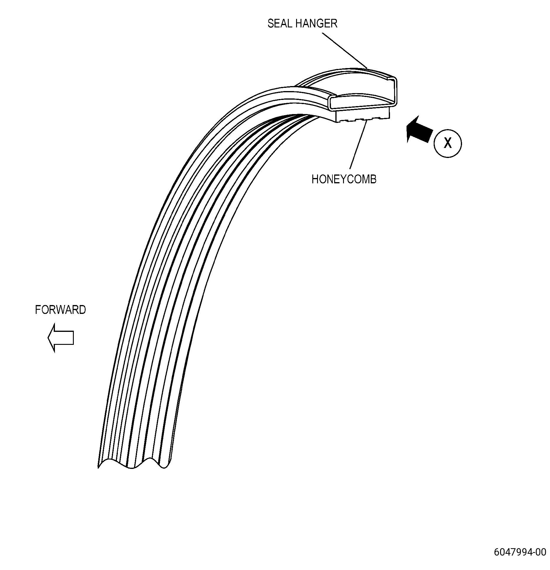
| A. | This procedure gives instructions to repair the high pressure compressor stator stage 4 interstage seals (seal) by replacing the worn or damaged honeycomb and by welding the worn seal hanger (hanger) ends. |
| B. | The following maximum repairable limits apply to this repair: |
| NOTE: |
|
| (4) | Visual Inspection. |
| • |
|
| (l) | Do an inspection of the HPC stator stages 3 and 4 interstage seals (interstage seals) (076A3, 076AC, 076A4, 076AD) as follows. Refer to Figure 805. |
| 2 | Grooves in the honeycomb: |
| Maximum repairable limit: |
|
| 3 | Damaged cells: |
| Maximum repairable limit: |
|
| • |
|
| (a) | Do an inspection of the seal hanger for: |
| 7 | Fretting or wear at both ends of the seal hanger (does not include stops): |
| Maximum repairable limit: |
|
| (b) | Do an inspection of the honeycomb for: |
| 1 | Grooves: |
| Maximum repairable limit: |
|
| 2 | Damaged or missing cells: |
| Maximum repairable limit: |
|
| 3 | Nicks, dents, pits, gouges, and tears: |
| Maximum repairable limit: |
|
| C. | The subsequent table gives a list of the part numbers that are applicable to this procedure. All part numbers are applicable to all paragraphs unless specified differently. |
|
|||||||||||||||||||||||||||||||
| D. | Proprietary/Complex Process Statement. |
| (1) | None. |
| 2 . | Tools, Equipment, and Materials. |
| NOTE: |
|
| A. | Tools and Equipment. |
| (1) | Special Tools. None. |
| (2) | Standard Tools and Equipment. |
| (3) | Locally Manufactured Tools. |
|
| B. | Consumable Materials. |
|
| C. | Referenced Procedures. |
|
| D. | Expendable Parts. None. |
| E. | SPD Information. |
| (1) | Spares Supplied. None. |
| (2) | Protected Spares. None. |
| (3) | Locally Manufactured Spares. |
|
| F. | Special Solutions. None. |
| G. | Test Specimens. None. |
| 3 . | Dimensional Information. |
| Subtask 72-32-06-220-014 |
| A. | Refer to Figure 901, Figure 904, Figure 906, and Figure 908 for specified dimensions and locations. |
| NOTE: |
|
| NOTE: |
|
| 4 . | Setup Information. |
| Subtask 72-32-06-350-001 |
| A. | Set-up the seal for machining as follows: |
| (1) | Restrain datum A flat to 0.004 inch (0.10 mm) or less. |
| 5 . | Procedure. |
| Subtask 72-32-06-120-002 |
| CAUTION: |
|
| A. | Optional Procedure. Clean all the surfaces of the hanger to remove oxides and all stubborn stains. Refer to TASK 70-21-04-120-001 (CLEANING METHOD NO. 4 - DRY ABRASIVE BLAST CLEANING) and as follows: |
| (1) | Use Method No. 4A or a different method with a less aggressive media. |
| (2) | Make sure that the hanger surface has a constant surface appearance and there is no remaining blasting material collected. |
| Subtask 72-32-06-350-002 |
| B. | Alternative Procedure Available. If you cannot fully read the assembly part number and manufacturer marking because it is faded, refer to TASK 70-16-00-350-001 (MARKING PRACTICES), TASK 70-16-06-350-022 (LASER MARKING), Figure 901, and do as follows: |
| (1) | Put a single line through the existing markings and put a new mark of the part number and manufacturer adjacent to the lined-out markings. |
| (2) | Use Method 1B. |
| (3) | New markings must not be nearer than 0.01 inch (0.2 mm) to a corner, fillet, or edge. |
| Subtask 72-32-06-350-003 |
| B.A. | Alternative Procedure. If you cannot fully read the assembly part number and manufacturer marking because it is faded, refer to TASK 70-16-00-350-001 (MARKING PRACTICES), TASK 70-16-08-350-001 (DOT PEEN MARKING FOR OPTICAL CHARACTER RECOGNITION), Figure 901, and do as follows: |
| (1) | Put a single line through the existing markings and put a new mark of the part number and manufacturer adjacent to the lined-out markings. |
| (2) | Use Method 1. |
| (3) | New markings must not be nearer than 0.01 inch (0.2 mm) to a corner, fillet, or edge. |
| Subtask 72-32-06-350-004 |
| C. | Alternative Procedure Available. Remove the honeycomb from the hanger. Refer to Figure 902 and do as follows: |
| (1) | Hold the hanger parallel to the belt sander. |
| WARNING: |
|
| CAUTION: |
|
| CAUTION: |
|
| (2) | Remove an equal quantity of honeycomb across the seal width. Refer to TASK 70-00-03-800-004 (MACHINING DATA), and as follows: |
| (a) | Grind the honeycomb until you have only honeycomb stubble. |
| (3) | Remove the seal from the grinding machine. |
| Subtask 72-32-06-350-005 |
| WARNING: |
|
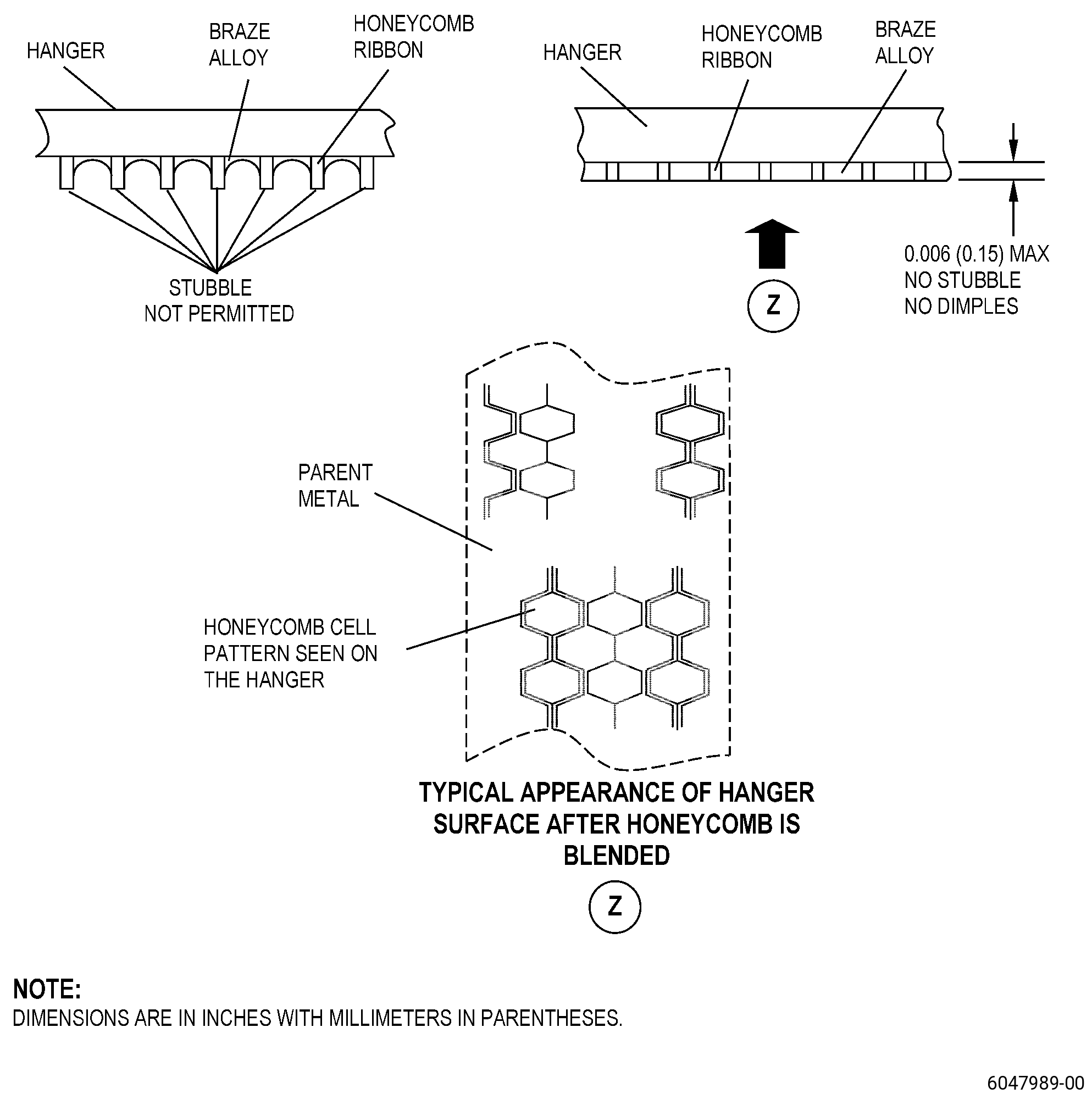
| (4) | Alternative Procedure Available. If necessary, blend the hanger to remove the remaining honeycomb and braze alloy to keep only a witness of the honeycomb pattern on the hanger. Refer to TASK 70-42-00-350-002 (BLENDING AND REMOVAL OF HIGH METAL PROCEDURES) and as follows: |
| (a) | Keep only a witness of the honeycomb pattern on the hanger. |
| (b) | It is not necessary to remove all the braze alloy from the hanger. |
| (c) | Make sure that you remove the minimum quantity of parent material from the hanger. |
| Subtask 72-32-06-350-006 |
| (4).A. | Alternative Procedure. Grind the seal to remove the remaining honeycomb and braze material from the seal backing strip and as follows: |
| (a) | Use a belt grinder with a 180-320 silicon carbide belt. |
| (b) | Keep only a witness of the honeycomb pattern on the hanger. |
| (c) | It is not necessary to remove all the braze alloy from the hanger. |
| (d) | Make sure that you remove the minimum quantity of parent material from the hanger. |
| Subtask 72-32-06-350-007 |
| C.A. | Alternative Procedure. Remove the honeycomb from the hanger. Refer to TASK 70-00-03-800-004 (MACHINING DATA), Figure 902, and do as follows: |
| WARNING: |
|
| CAUTION: |
|
| CAUTION: |
|
| (1) | Remove the honeycomb from the hanger with a vibrating chisel power tool and as follows: |
| (a) | Do not remove the parent material. |
| Subtask 72-32-06-350-008 |
| WARNING: |
|
| (2) | Alternative Procedure Available. Blend the seal as necessary to remove the remaining honeycomb and braze alloy to keep only a witness of the honeycomb pattern on the hanger. Refer to TASK 70-42-00-350-002 (BLENDING AND REMOVAL OF HIGH METAL PROCEDURES) and as follows: |
| (a) | Keep only a witness of the honeycomb pattern on the hanger. |
| (b) | It is not necessary to remove all the braze alloy from the hanger. |
| (c) | Make sure that you remove the minimum quantity of parent material from the hanger. |
| Subtask 72-32-06-350-009 |
| (2).A. | Alternative Procedure. Grind the seal to remove the remaining honeycomb and braze material from the hanger and as follows: |
| (a) | Use a belt grinder with a 180-320 silicon carbide belt. |
| (b) | Keep only a witness of the honeycomb pattern on the hanger. |
| (c) | It is not necessary to remove all the braze alloy from the hanger. |
| (d) | Make sure that you remove the minimum quantity of parent material from the hanger. |
| Subtask 72-32-06-220-015 |
| D. | Do an inspection of the hanger in the area where you removed the honeycomb. Refer to Figure 902, Figure 904, Figure 905, Figure 906, and as follows: |
| (1) | Measure the thickness of the hanger at a location where you fully removed the honeycomb and the braze alloy, and as follows: |
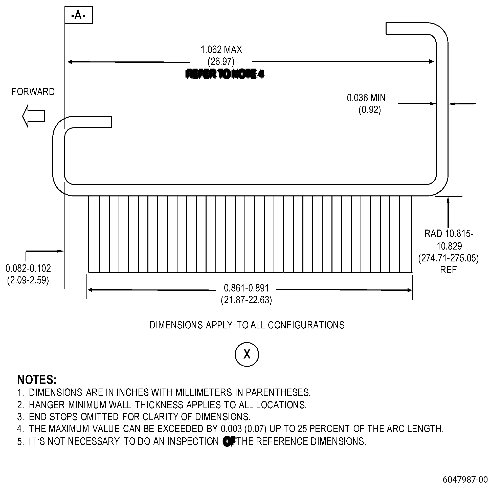
| (a) | The hanger must have a minimum serviceable thickness of 0.036 inch (0.92 mm). |
| (b) | If the hanger thickness is less than the minimum serviceable limit, the seal is not repairable with this repair procedure. Replace the seal. |
| (c) | If the hanger does not have areas of exposed parent material, it is not necessary to measure its thickness. |
| (2) | Do an inspection of the hanger contour as follows: |
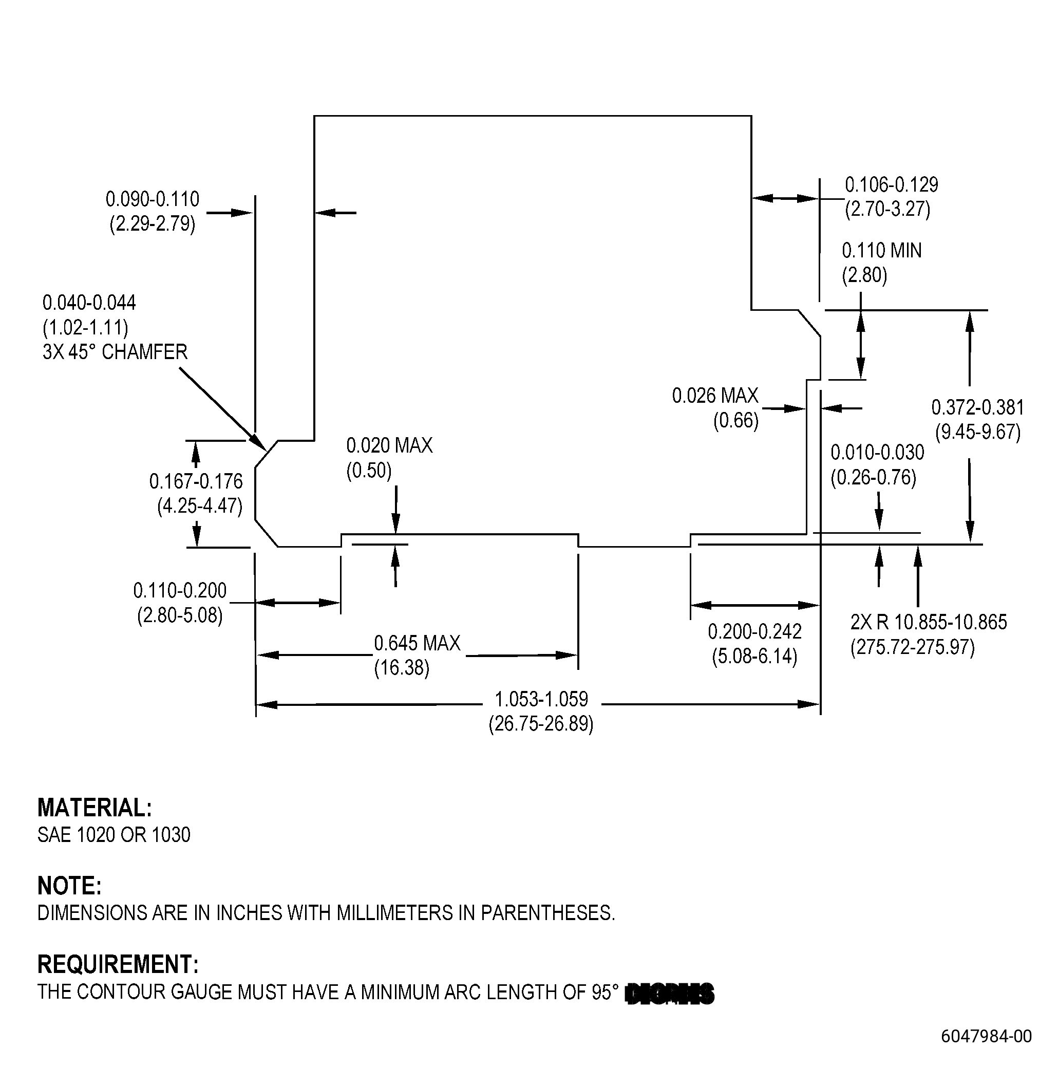
| (a) | If necessary, make the contour gauge. Refer to TASK 70-31-06-220-001 (MACHINED FEATURES SHOP-RUN TOLERANCES). |
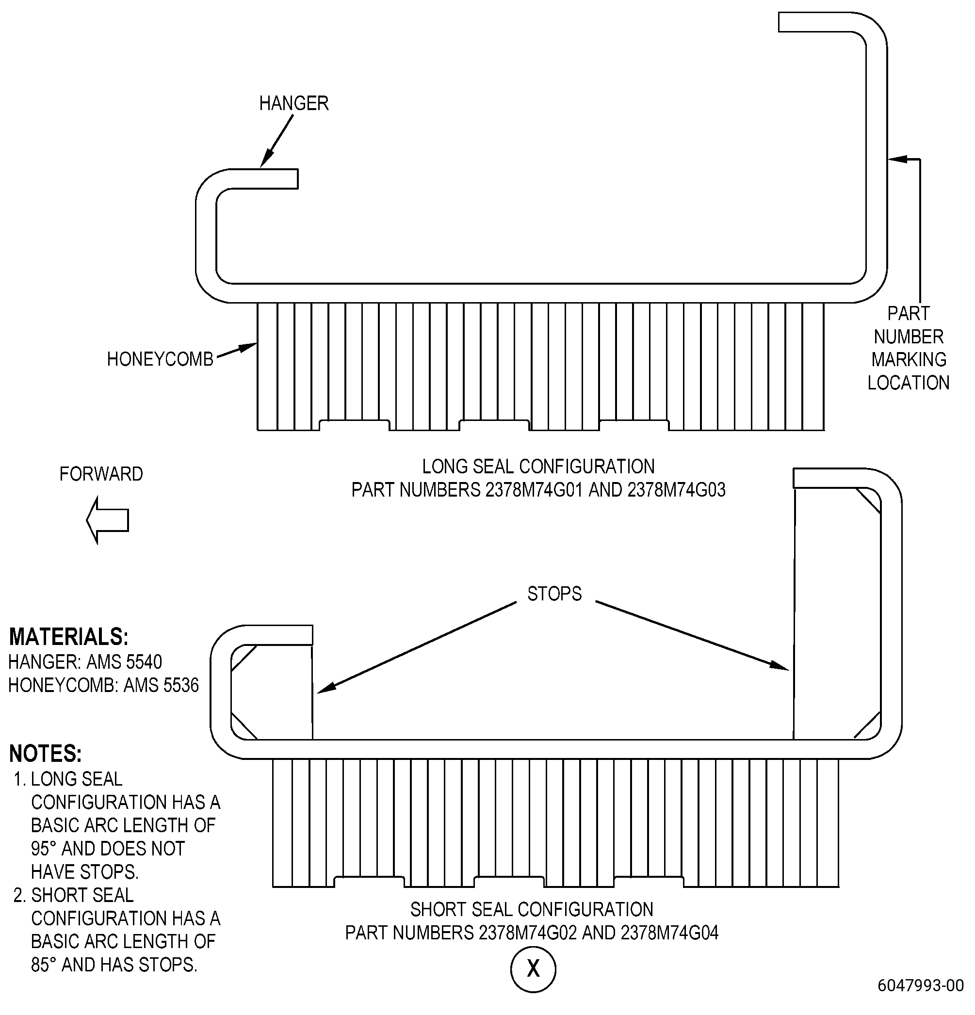
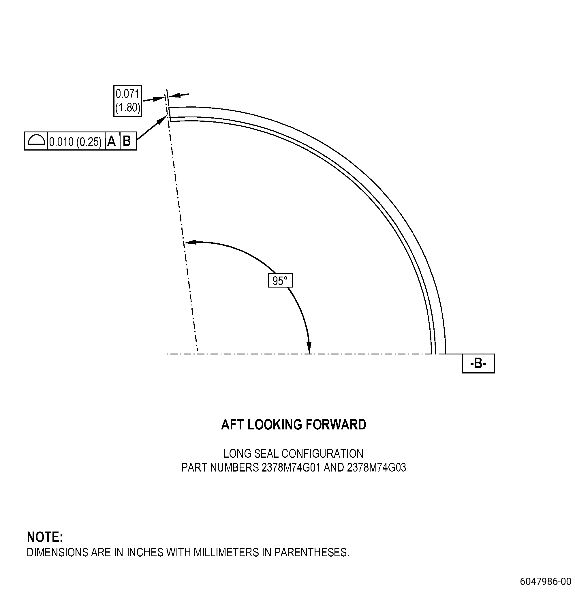
| (b) | In free state, the contour gauge must manually go freely through the full arc length of the long seal configuration. |
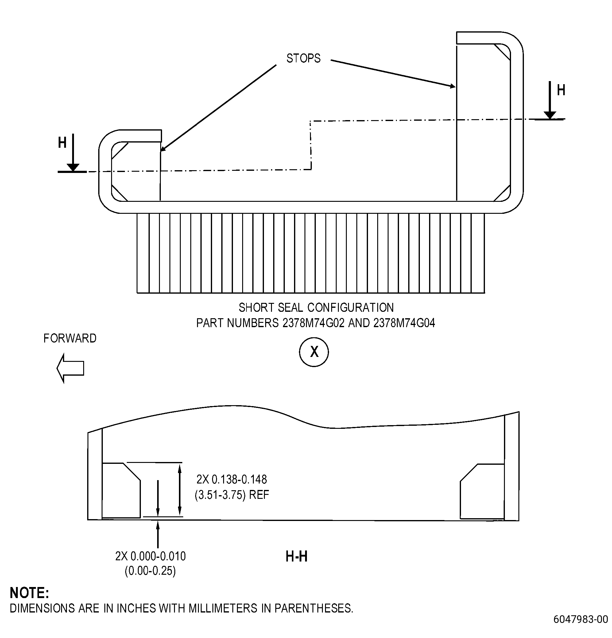
| (c) | In free state, the contour gauge must manually go freely through the arc length of the short seal configuration until the contour gauge touches the stops. |
| (d) | Make sure that the hanger goes freely through the contour gauge. |
| Subtask 72-32-06-350-010 |
| E. | If the hanger does not go freely through the contour gauge, cold-work the hanger to the correct contour. Refer to TASK 70-47-05-350-023 (COLD-WORKING REPAIR), Figure 904, Figure 905, and as follows: |
| (1) | After you cold-work the seal, do an inspection of the hanger contour. Refer to Subtask 72-32-06-220-015 (paragraph 5.D.(2)). |
| Subtask 72-32-06-350-011 |
| F. | Measure the hanger arc length. Refer to Figure 904 and as follows: |
| (1) | Identify the parts that are shorter than the minimum serviceable arc length for weld build-up. |
| Subtask 72-32-06-310-001 |
| G. | If necessary, weld the hangers that are shorter than the minimum serviceable arc length as follows: |
| CAUTION: |
|
| (1) | Apply weld stock to the worn end of the hanger to repair the arc length. Refer to TASK 70-41-00-310-001 (WELDING AND BRAZING PRACTICES) and as follows: |
| (a) | Use C06-050 weld wire. |
| Subtask 72-32-06-350-012 |
| WARNING: |
|
| CAUTION: |
|
| H. | Blend all the weld stock inner diameter (ID) and outer diameter (OD). Refer to TASK 70-42-00-350-002 (BLENDING AND REMOVAL OF HIGH METAL PROCEDURES), Figure 904, Figure 906, and as follows: |
| (1) | Blend all the weld stock ID and OD smooth with the hanger ID and OD surfaces only, and as follows: |
| (a) | Do not remove the hanger parent material. |
| (b) | The weld areas can protrude 0.001-0.005 inch (0.03-0.12 mm) above the adjacent parent material surface areas. |
| (2) | Do not blend the end of the weld stock to repair the hanger arc length. The arc length will be repaired in a subsequent step of this repair. |
| (3) | Polish all the weld stock ID and OD surfaces with a Scotch Brite wheel. |
| (4) | Measure the hanger thickness in the blend/polish area to make sure that it is equal to or more than the minimum serviceable limit of 0.036 inch (0.92 mm). |
| Subtask 72-32-06-110-007 |
| WARNING: |
|
| I. | Clean the hanger. Refer to TASK 70-21-00-110-051 (CHEMICAL CLEANING), TASK 70-21-23-110-053 (CLEANING METHOD NO. 23 - HAND-WIPE DEGREASING), and as follows: |
| Subtask 72-32-06-110-008 |
| (1) | Alternative Procedure Available. Use C04-003 acetone to clean the mating surface of the hanger and the replacement honeycomb. |
| Subtask 72-32-06-110-009 |
| (1).A. | Alternative Procedure. Use C04-035 isopropyl alcohol to clean the mating surface of the hanger and the replacement honeycomb. |
| Subtask 72-32-06-110-010 |
| J. | Etch the hanger OD in the repair areas. Refer to TASK 70-24-00-110-033 (ETCHING PROCEDURES FOR FLUORESCENT-PENETRANT INSPECTION), TASK 70-24-01-110-034 (SWAB ETCHING PROCEDURE), and as follows: |
| (1) | Use Class C etchant. |
| Subtask 72-32-06-230-003 |
| K. | Do an inspection of the hanger OD in the repair area. Refer to TASK 70-32-00-200-002 (INDIRECT INSPECTION METHODS), TASK 70-32-03-230-002 (SPOT-FLUORESCENT-PENETRANT INSPECTION), and as follows: |
| (1) | Use Class A penetrant. |
| (2) | Refer to TASK 70-31-02-220-003 (ACCEPTABILITY LIMITS FOR FLUORESCENT PENETRANT INSPECTION) and as follows: |
| (a) | Use Class A limits. |
| Subtask 72-32-06-220-016 |
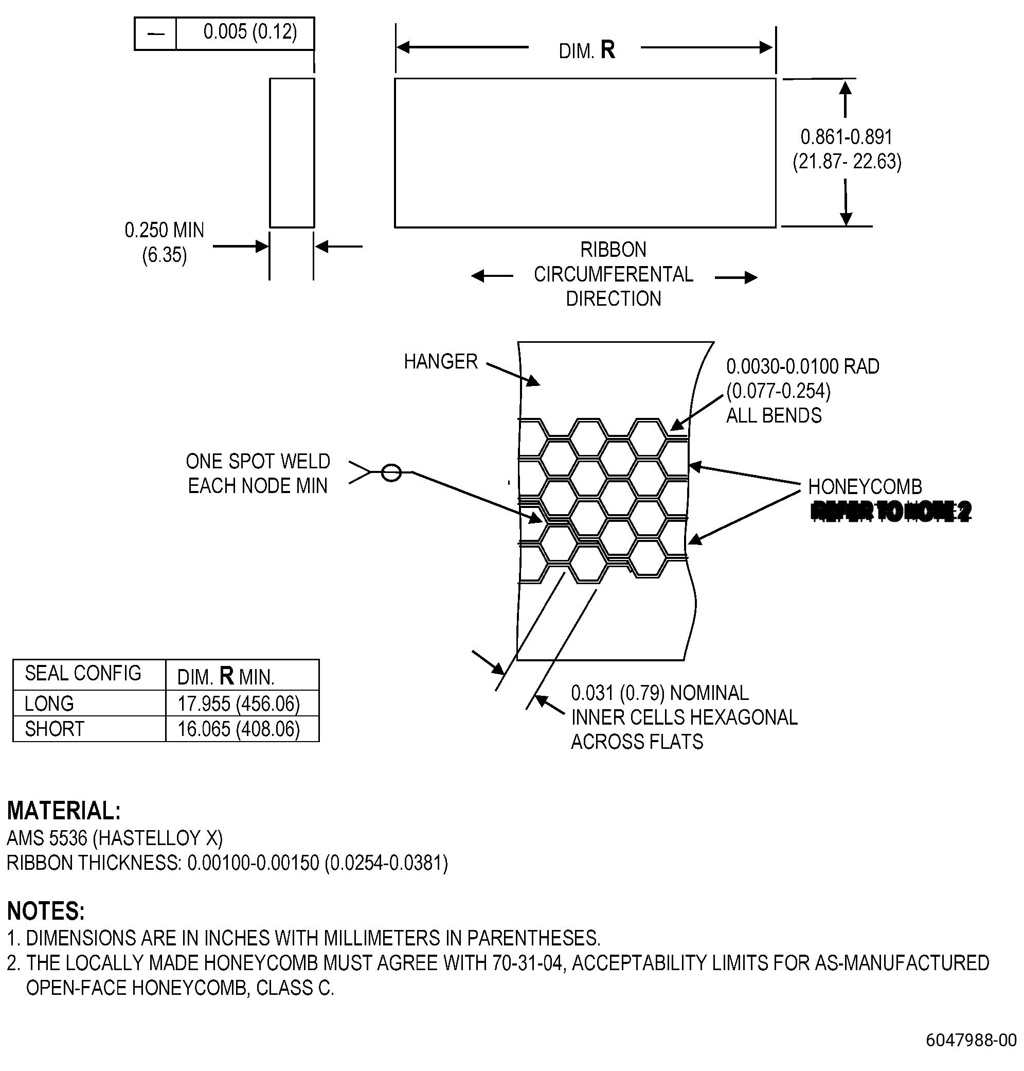
| L. | Make the replacement honeycomb. Refer to TASK 70-31-04-220-001 (ACCEPTABILITY LIMITS FOR AS-MANUFACTURED OPEN-FACE HONEYCOMB), Figure 903, and as follows: |
| (1) | Use Class C limits. |
| Subtask 72-32-06-110-011 |
| M. | Alternative Procedure Available. Clean the hanger and the replacement honeycomb. Refer to TASK 70-21-00-110-051 (CHEMICAL CLEANING), TASK 70-21-22-110-801 (CLEANING METHOD NO. 22 - LIGHT DUTY AQUEOUS CLEANING), and as follows: |
| (1) | Use Method No. 1. |
| Subtask 72-32-06-160-002 |
| M.A. | Alternative Procedure. Clean the hanger and the replacement honeycomb. Refer to TASK 72-36-06-100-801 (72-32-06, CLEANING 001). |
| Subtask 72-32-06-110-012 |
| WARNING: |
|
| M.B. | Alternative Procedure. Clean the hanger and the replacement honeycomb. Refer to TASK 70-21-00-110-051 (CHEMICAL CLEANING), TASK 70-21-23-110-053 (CLEANING METHOD NO. 23 - HAND-WIPE DEGREASING), and as follows: |
| Subtask 72-32-06-110-013 |
| (1) | Alternative Procedure Available. Use C04-003 acetone to clean the mating surface of the hanger and the replacement honeycomb. |
| Subtask 72-32-06-110-014 |
| (1).A. | Alternative Procedure. Use C04-035 isopropyl alcohol to clean the mating surface of the hanger and the replacement honeycomb. |
| Subtask 72-32-06-330-001 |
| N. | Optional Procedure. Alternative Procedure Available. Nickel-plate the hanger surface at the honeycomb area. Refer to TASK 70-45-03-330-004 (SELECTIVE CONTACT PLATING), AMS 2403 - Plating, Nickel, General Purpose, Figure 904, and as follows: |
| NOTE: |
|
| (1) | Nickel plate thickness must be 0.00016-0.00031 inch (0.0041-0.0078 mm). |
| Subtask 72-32-06-120-003 |
| WARNING: |
|
| N.A. | Optional Procedure. Alternative Procedure. Clean the hanger surface at the honeycomb. Refer to TASK 70-21-04-120-001 (CLEANING METHOD NO. 4 - DRY ABRASIVE BLAST CLEANING), Figure 902, Figure 904, and as follows: |
| NOTE: |
|
| (1) | Use C06-028 nicroblast media. |
| (2) | Use an air pressure of 40-60 psi (276-414 kPa). |
| (3) | Keep the nozzle 6.0-8.0 inches (153-203 mm) from the surface. |
| Subtask 72-32-06-310-002 |
| CAUTION: |
|
| O. | Optional Procedure. Apply C06-066 braze alloy (AMS 4777) in tape form with an approximate thickness of 0.020-0.030 inch (0.51-0.76 mm) to the OD of the replacement honeycomb. Refer to Figure 904 and as follows: |
| (1) | If necessary, make a coupon to simulate the brazing process of the seal to the replacement honeycomb and as follows: |
| NOTE: |
|
| (a) | Find the thickness of the C06-066 braze alloy (AMS 4777) in tape form that will get the best brazing results for the replacement honeycomb. |
| (2) | Apply C06-066 braze alloy (AMS 4777) in tape form to the OD of the replacement honeycomb. |
| (3) | Use a scraper to remove all the unwanted braze alloy from the OD of the replacement honeycomb. |
| Subtask 72-32-06-310-003 |
| CAUTION: |
|
| CAUTION: |
|
| CAUTION: |
|
| CAUTION: |
|
| P. | Weld the replacement honeycomb to the hanger. Refer to TASK 70-41-00-310-001 (WELDING AND BRAZING PRACTICES), TASK 70-41-04-310-005 (RESISTANCE WELDING - SPOT, SEAM, AND PROJECTION), Figure 904, and as follows: |
| (1) | Put the replacement honeycomb in the correct location on the hanger and as follows: |
| (a) | The replacement honeycomb must extend more than the two circumferential ends of the hanger. |
| NOTE: |
|
| CAUTION: |
|
| (2) | Adjust the resistance tack weld parameters to get a satisfactory weld between the replacement honeycomb and the hanger, and as follows: |
| (a) | Do a visual inspection of the tack welds to make sure that the replacement honeycomb is correctly attached to the hanger. |
| (b) | If you find burn marks in the replacement honeycomb, make sure that they are sufficiently shallow to remove them during the final machining procedure. |
| (3) | Align the electrodes with the approximate center of the replacement honeycomb and make a tack weld. |
| (4) | Continue to make tack welds until you attach the replacement honeycomb along the full length of the hanger. |
| Subtask 72-32-06-220-017 |
| Q. | Do a dimensional inspection of the seal. Refer to Figure 904. |
| Subtask 72-32-06-220-018 |
| R. | Do a visual inspection of the seal as follows: |
| (1) | The replacement honeycomb must be tightly attached to the hanger as follows: |
| (a) | The space between the replacement honeycomb and the hanger must be 0.000-0.005 inch (0.00-0.12 mm) maximum. |
| (2) | Examine the replacement honeycomb for open nodes as follows: |
| (a) | Open nodes are not permitted. |
| (b) | If necessary, use a tweezer to close all open nodes. |
| (3) | Examine the electrical ground areas for burns and pits as follows: |
| (a) | Burns are not permitted on the hanger. |
| (b) | If you find pits, use the acceptability limits that follow: |
| 1 | Pits of 0.005 inch (0.12 mm) maximum in depth are permitted. |
| 2 | Pits of 0.030 inch (0.76 mm) maximum in diameter are permitted. |
| (c) | Pits larger than these limits are not permitted. |
| Subtask 72-32-06-350-013 |
| WARNING: |
|
| CAUTION: |
|
| (4) | If necessary, blend the electrical ground areas to remove pits. Refer to TASK 70-42-00-350-002 (BLENDING AND REMOVAL OF HIGH METAL PROCEDURES), and as follows: |
| (a) | Blend the pits that are in the limits in Subtask 72-32-06-220-018 (paragraph 5.R.(3)(b)) only. |
| (b) | Blend the pits until they are no more than the limits in Subtask 72-32-06-220-018 (paragraph 5.R.(3)(b)). |
| Subtask 72-32-06-310-004 |
| WARNING: |
|
| CAUTION: |
|
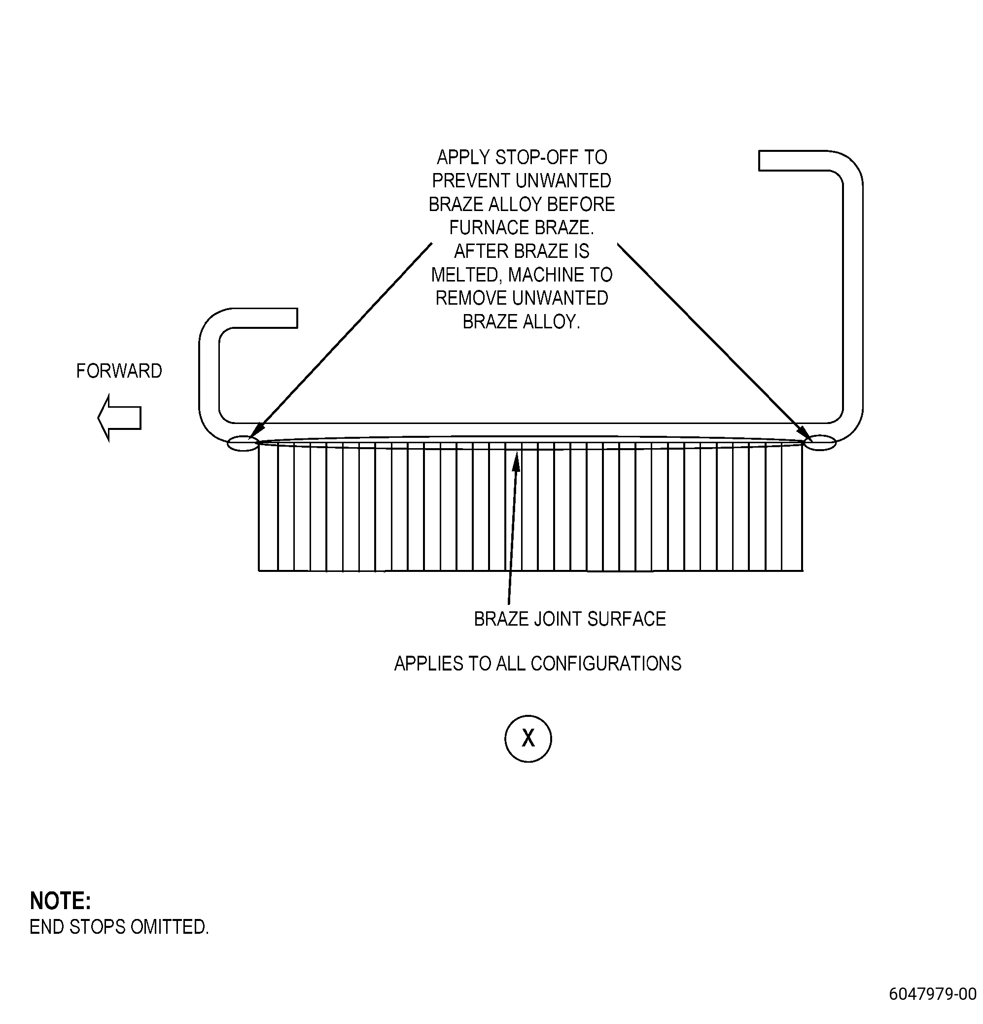
| S. | Prepare the seal for brazing. Refer to TASK 70-41-00-310-001 (WELDING AND BRAZING PRACTICES), TASK 70-41-03-310-004 (HIGH TEMPERATURE FURNACE BRAZE), Figure 907, and as follows: |
| (1) | If you used C06-066 braze alloy (AMS 4777) in tape form, go to Subtask 72-32-06-310-004 (paragraph 5.S.(7)). |
| (2) | Apply C06-062 braze alloy powder equally in the replacement honeycomb cells. Make sure that there is sufficient C06-062 braze alloy powder at the bottom of each cell. |
| (3) | Use a high intensity light to examine the bottom of the cells to make sure that sufficient C06-062 braze alloy powder is in each of the cells. |
| (4) | If necessary, remove the unwanted C06-062 braze alloy powder with a C10-108 brush. |
| WARNING: |
|
| CAUTION: |
|
| (5) | Spray C01-034 acrylic binder into the cells and let dry. |
| NOTE: |
|
| (6) | Mix 85 to 90 percent of C06-062 braze alloy powder and 10 to 15 percent in weight of C06-019 braze binder until it becomes a slurry. |
| (7) | Apply the slurry along the full length of the two sides of the replacement honeycomb to make a fillet. |
| WARNING: |
|
| (8) | Apply a layer of approximately 0.005-0.015 inch (0.13-0.38 mm) in thickness of C10-020 braze stop-off at the forward edge and the aft edge, and around the axial edges of the replacement honeycomb on the hanger. |
| NOTE: |
|
| Subtask 72-32-06-310-005 |
| T. | Braze the replacement honeycomb to the hanger. Refer to TASK 70-41-00-310-001 (WELDING AND BRAZING PRACTICES), TASK 70-41-03-310-004 (HIGH TEMPERATURE FURNACE BRAZE), and as follows: |
| (1) | Put the load thermocouples on the seal and as follows: |
| (a) | Use the quantity and location requirements of the load thermocouples as specified in TASK 70-41-03-310-004 (HIGH TEMPERATURE FURNACE BRAZE). |
| (2) | If necessary, use a locally made holding fixture to keep the seal shape. |
| (3) | Put the seal in the furnace. |
| (4) | Alternative Procedure Available. Braze the seal in a vacuum furnace with a vacuum of 1x10⁻³ torr (0.13 Pa) or better. |
| (4).A. | Alternative Procedure. Braze the seal in a hydrogen furnace at a dew point of -60°F (-51°C) or better. |
| (5) | Increase the temperature of the seal to a range of 1700 to 1800°F (927 to 982°C) and hold the temperature for 10 to 15 minutes. |
| NOTE: |
|
| CAUTION: |
|
| (6) | Increase the temperature of the seal at a maximum rate of 35°F (19°C) for each minute to 1875 to 1925°F (1024 to 1052°C) and hold the temperature for a maximum of 5 minutes. |
| (7) | Decrease the temperature of the seal to 1700 to 1800°F (927 to 982°C) at a maximum rate of 35°F (19°C) for each minute and hold the temperature for a maximum of 15 minutes. |
| CAUTION: |
|
| (8) | Decrease the temperature of the seal to 1000°F (538°C) in 30 minutes or less in vacuum or inert gas atmosphere. |
| NOTE: |
|
| (9) | Decrease the temperature of the seal to room temperature. |
| WARNING: |
|
| (10) | Remove the seal from the furnace. |
| Subtask 72-32-06-220-019 |
| U. | Alternative Procedure Available. Do an inspection of the seal. Refer to TASK 70-33-00-999-001 (SPECIAL INSPECTION PROCEDURES), TASK 70-33-02-220-005 (CAPILLARY INSPECTION OF OPEN FACE HONEYCOMB STRUCTURES). |
| Subtask 72-32-06-220-020 |
| U.A. | Alternative Procedure. Do an inspection of the seal with a video microscope and as follows: |
| (1) | Use minimum 10X magnification. |
| (2) | The replacement honeycomb must be fully bonded to the hanger in 80 percent of the total area. |
| (3) | The total areas of the cells in an unbonded area must not be more than 0.25 inch x 0.25 inch (6.4 mm x 6.4 mm) or 0.06 sq inch (38.7 sq mm). |
| (4) | Unbonded areas must not be more than one-third of the total width of the replacement honeycomb. |
| (5) | A maximum of five unbonded areas of 0.06 sq inch (38.7 sq mm) are permitted. |
| (6) | A maximum of two 0.06 sq inch (38.7 sq mm) unbonded areas at the edge of the replacement honeycomb are permitted. |
| (7) | There must be a minimum distance of 0.5 inch (13 mm) between unbonded areas. |
| (8) | A pair of cells with the same unbonded wall must not be interpreted as an unbonded area. |
| (9) | The replacement honeycomb core must be bonded at 90 percent of its nodes. |
| (10) | Less than 10 percent of the cell height must be filled with braze material. |
| (11) | The replacement honeycomb cells can have a maximum of three adjacent cells plugged with braze alloy if the distance to a different cluster or string is a minimum of 3.0 inches (77 mm) circumferentially or 0.20 inch (5.1 mm) axially. |
| Subtask 72-32-06-320-001 |
| V. | If necessary, machine the seal to remove the remaining braze alloy from the replacement honeycomb cells. Refer to TASK 70-00-03-800-004 (MACHINING DATA), and as follows: |
| (1) | Not more than two percent of the cells in a circumferential row can have remaining braze alloy removed. |
| (2) | Alternative Procedure Available. Use a jeweler's drill to remove the remaining braze alloy. |
| (2).A. | Alternative Procedure. Use an electrical discharge machining (EDM) to remove the remaining braze alloy and as follows: |
| (a) | Maximum intergranular attack permitted is 0.0025 inch (0.063 mm). |
| (b) | Maximum microcracks permitted is 0.0025 inch (0.063 mm). |
| (c) | Maximum continuous recast permitted is 0.0025 inch (0.063 mm). |
| (d) | Maximum local recast permitted is 0.0030 inch (0.076 mm). |
| Subtask 72-32-06-350-014 |
| WARNING: |
|
| W. | Blend the seal to remove all the unwanted braze alloy in the area adjacent to the replacement honeycomb. Refer to TASK 70-42-00-350-002 (BLENDING AND REMOVAL OF HIGH METAL PROCEDURES), Figure 907, and do as follows: |
| (1) | Use a Scotch Brite wheel to remove the unwanted braze material. |
| Subtask 72-32-06-320-002 |
| WARNING: |
|
| CAUTION: |
|
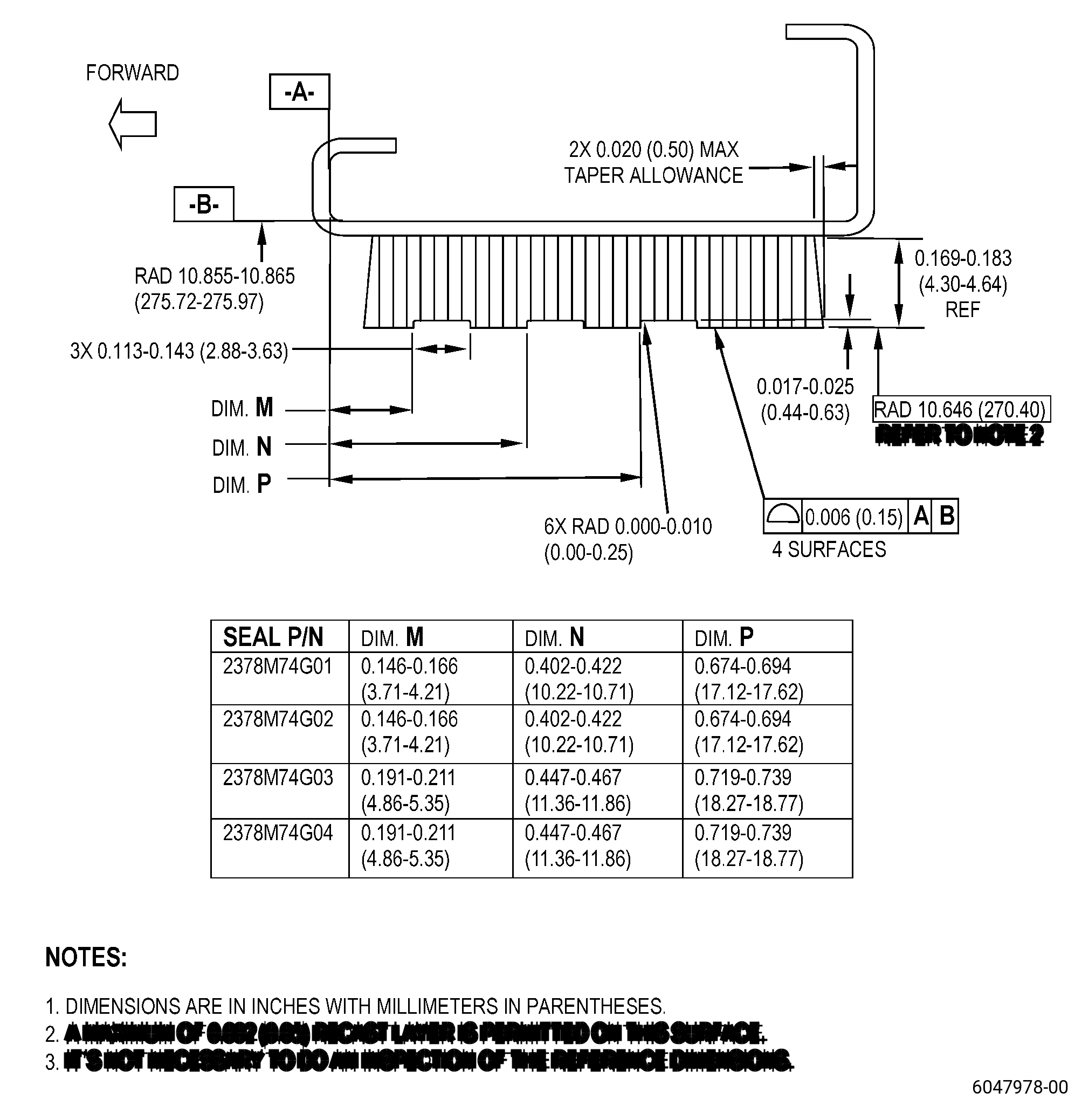
| X. | Machine the seal to remove the unwanted replacement honeycomb and weld build-up at one end of the hanger. Refer to TASK 70-00-03-800-004 (MACHINING DATA), Figure 904, Figure 906, Figure 908, and as follows: |
| (1) | If there is weld build-up at one end of the hanger, grind the weld build-up to repair the hanger arc length. |
| (2) | Use a cut-off wheel or belt grinder to cut the replacement honeycomb flush to 0.000-0.001 inch (0.00-0.02 mm) of the ends of the hanger. |
| (3) | Remove all burrs from the seal. |
| (4) | Measure the hanger arc length as follows: |
| (a) | If there are parts shorter than the minimum serviceable arc length, do this repair again. Go to Subtask 72-32-06-120-002 (paragraph 5.A.). |
| Subtask 72-32-06-220-021 |
| Y. | Do an inspection of the seal contour. Refer to Figure 904, Figure 906, and as follows: |
| (1) | In free state, the contour gauge must manually go freely through the full arc length of the long seal configuration. |
| (2) | In free state, the contour gauge must pass freely manually through the arc length of the short seal configuration until the contour gauge touches the stops. |
| (3) | Make sure that the hanger goes freely through the contour gauge. |
| Subtask 72-32-06-350-015 |
| Z. | If the seal does not go freely through the contour gauge, cold-work the seal to the correct contour. Refer to TASK 70-47-05-350-023 (COLD-WORKING REPAIR), Figure 904, and as follows: |
| (1) | After you cold-work the seal, do an inspection of the seal contour again. Refer to Subtask 72-32-06-220-021 (paragraph 5.Y.). |
| Subtask 72-32-06-320-003 |
| AA. | Alternative Procedure Available. Machine the replacement honeycomb seal to the finish dimensions. Refer to TASK 70-00-03-800-004 (MACHINING DATA), Figure 908, and do as follows: |
| Subtask 72-32-06-350-016 |
| (1) | Set-up the seal for machining of the honeycomb. Refer to Subtask 72-32-06-350-001 (paragraph 4.A.). |
| Subtask 72-32-06-320-004 |
| (2) | Machine the honeycomb seal diameter. |
| (3) | Remove burrs from the seal with a C10-097 wire brush. |
| Subtask 72-32-06-220-022 |
| (4) | Do a dimensional inspection of the seal as follows: |
| (a) | All dimensions must agree with datum B held to the dimensional tolerance and datum A held flat to 0.004 inch (0.10 mm) or less. |
| Subtask 72-32-06-320-005 |
| AA.A. | Alternative Procedure. EDM the replacement honeycomb seal to the finish dimensions. Refer to TASK 70-00-03-800-004 (MACHINING DATA), Figure 908, and as follows: |
| Subtask 72-32-06-350-017 |
| (1) | Set-up the seal for machining of the honeycomb. Refer to Subtask 72-32-06-350-001 (paragraph 4.A.). |
| Subtask 72-32-06-220-023 |
| (2) | Do an inspection of the replacement honeycomb. Refer to TASK 70-31-05-220-001 (ENGINE PART SURFACE INTEGRITY ACCEPTABILITY LIMITS FOR NONTRADITIONAL MACHINED SURFACES) and as follows: |
| (a) | Use Class H limits. |
| (b) | The maximum recast layer can be 0.0020 inch (0.050 mm). |
| (3) | Do a dimensional inspection of the seal as follows: |
| (a) | All dimensions must agree with datum B held to the dimensional tolerance and datum A held flat to 0.004 inch (0.10 mm) or less. |
| Subtask 72-32-06-160-003 |
| AB. | Clean the seal. Refer to TASK 72-36-06-100-801 (72-32-06, CLEANING 001). |
| Subtask 72-32-06-110-015 |
| AC. | Optional Procedure. Clean all the surfaces of the seal. Refer to TASK 70-21-04-120-001 (CLEANING METHOD NO. 4 - DRY ABRASIVE BLAST CLEANING) and do as follows: |
| (1) | Use Method No. 4C. |
| (2) | Make sure that the hanger surface has a constant surface appearance and there is no remaining blasting material collected. |
| (3) | The surface finish must be 125 microinches (3.2 micrometers) or better. |
| Subtask 72-32-06-220-024 |
| AD. | Do an inspection of the braze joints. Refer to TASK 70-32-00-200-002 (INDIRECT INSPECTION METHODS), TASK 70-32-11-220-011 (WHITE LIGHT INSPECTION) , and as follows: |
| (1) | Use a white light and 10X magnification. |
| (2) | Linear indications are not permitted. |
| NOTE: |
|
| Subtask 72-32-06-220-025 |
| AE. | Do an inspection of the seal. Refer to TASK 72-32-06-200-801 (72-32-06, INSPECTION 001) and as follows: |
| (1) | If the hanger was cold-worked to restore hanger contour, do FPI and visual inspection. |
| (2) | If the hanger was not cold-worked to restore hanger contour, do visual inspection. |