| GENX-1B CLEANING,INSPECTION,AND REPAIR MANUAL | Dated: 10/31/2018 | |
| CIR 72-32-01 , REPAIR 002 | ||
| HIGH PRESSURE COMPRESSOR STATOR FORWARD CASE ASSEMBLY - REPAIR- SELF-LOCKING INSERT REPLACEMENT | ||
| GENX-1B CLEANING,INSPECTION,AND REPAIR MANUAL | Dated: 10/31/2018 | |
| CIR 72-32-01 , REPAIR 002 | ||
| HIGH PRESSURE COMPRESSOR STATOR FORWARD CASE ASSEMBLY - REPAIR- SELF-LOCKING INSERT REPLACEMENT | ||
| * * * FOR ALL |
| TASK 72-32-01-300-802 |
| 1 . | Repair for the High Pressure Compressor Stator Forward Case. |
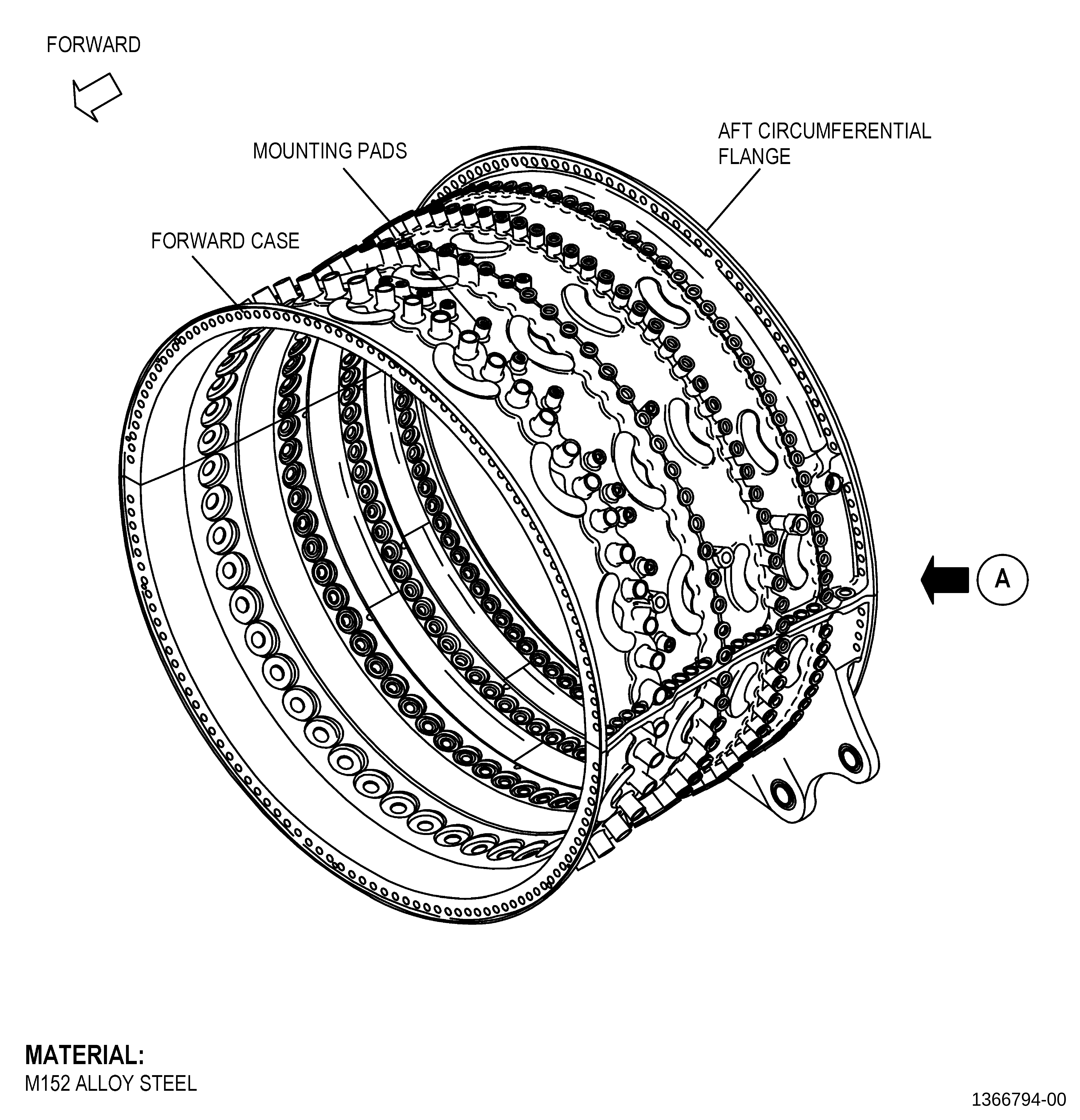
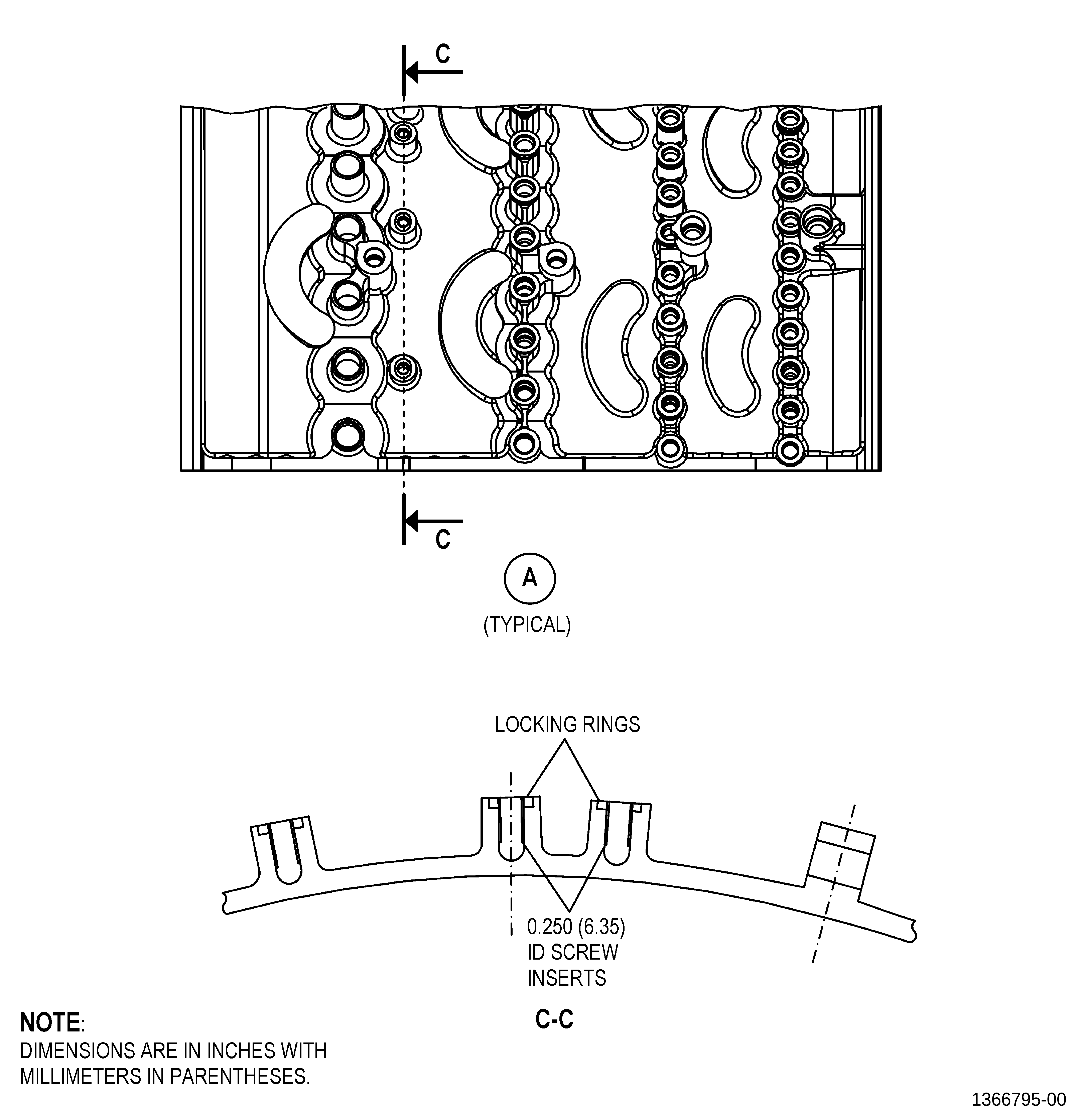
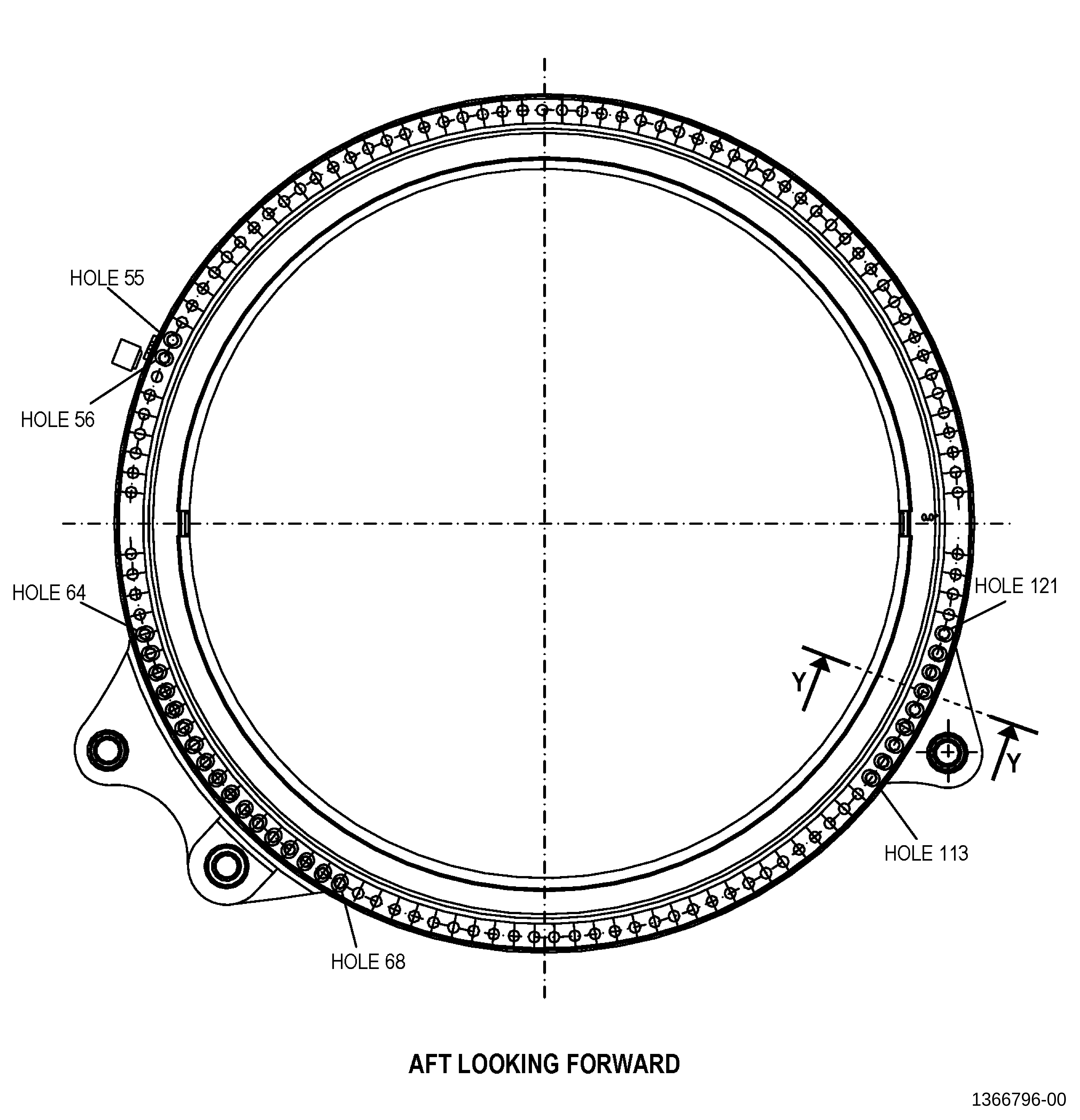
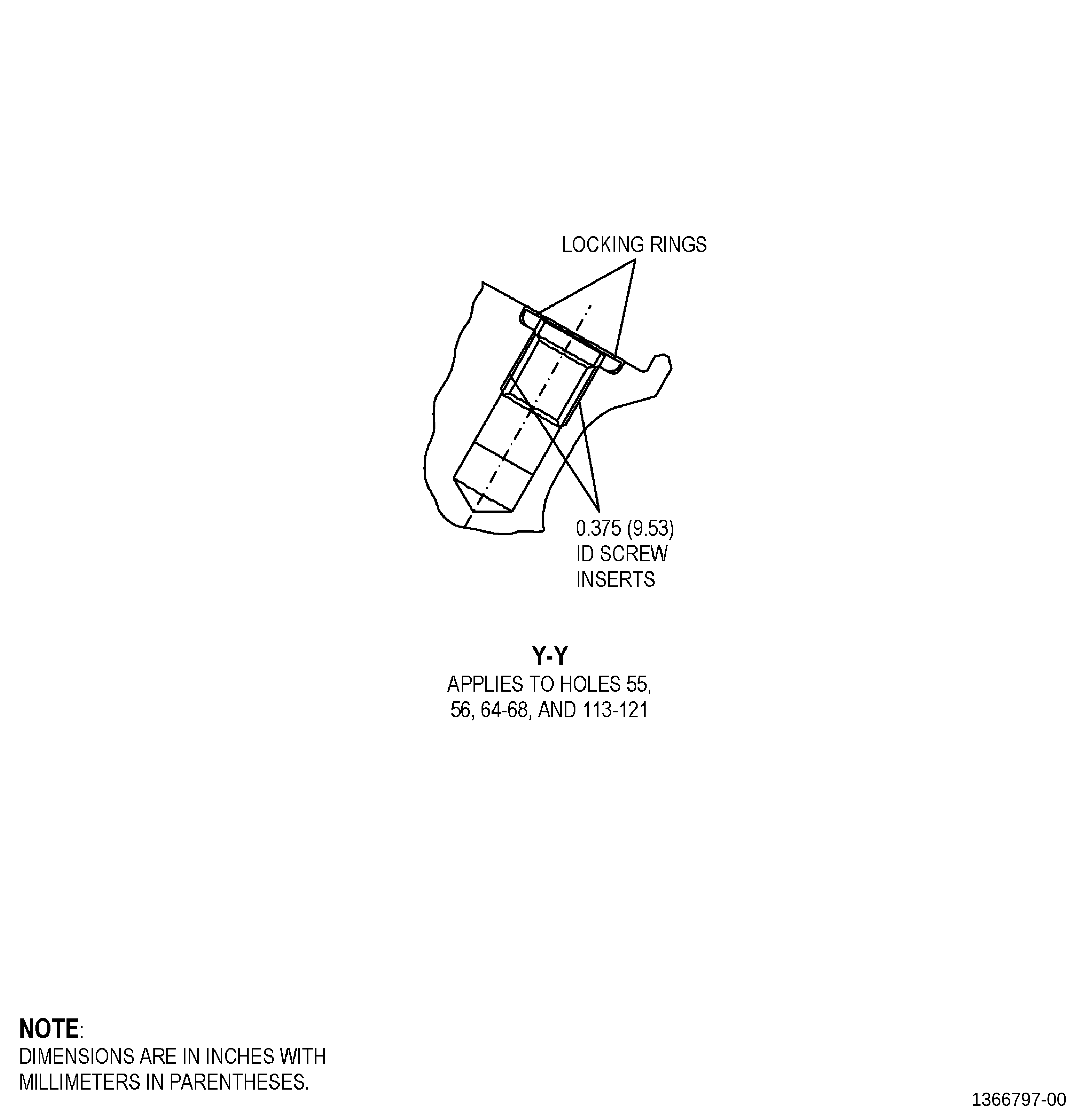
| A. | This procedure gives instructions to repair the HPC stator forward case assembly (forward case) by replacing damaged self-locking inserts. Refer to Figure 901. |
| B. | The following maximum repairable limits apply to this repair: |
| NOTE: |
|
| NOTE: |
|
| (4) | Visual Inspection. |
| (ad) | Do an inspection of the HPC stator forward case assembly (forward case assembly) (073A0) of the HPC assembly (00108) as follows. Refer to Figure 801 and Figure 810. |
| 5 | Damaged insert threads on the mounting pads or bosses: |
| Maximum repairable limit: |
|
| (ae) | Do an inspection of the machine bolts (bolt) (07320) in the unused forward case assembly mounting bosses (case bosses) as follows. Refer to Figure 810. |
| 2 | Damaged insert threads on the bosses: |
| Maximum repairable limit: |
|
| NOTE: |
|
| (4) | Visual Inspection. |
| (a) | Do an inspection of the HPC stator forward case assembly (case assembly) (073A0) as follows. Refer to Figure 801. |
| 11 | Loose, missing, or damaged insert threads on the mounting pads, bosses, and aft circumferential flange: |
| Maximum repairable limit: |
|
| NOTE: |
|
| (4) | Visual Inspection. |
| (h) | Do an inspection of the self-locking inserts of the mounting pads, bosses, and aft circumferential flange for: |
| 1 | Loss of self-locking quality of the 0.250-28UNF-3B insert (mounting pads and bosses): |
| Maximum repairable limit: |
|
| 2 | Loss of self-locking quality of the 0.375-24UNF-3B insert (aft circumferential flange): |
| Maximum repairable limit: |
|
| 3 | Loose or missing insert: |
| Maximum repairable limit: |
|
| C. | The subsequent table gives a list of the part numbers that are applicable to this repair. All part numbers are applicable to all paragraphs unless specified differently. |
|
||||||||||||||||||||||||||||||||||||
| D. | Proprietary/Complex Process Statement. |
| (1) | None. |
| 2 . | Tools, Equipment, and Materials. |
| NOTE: |
|
| A. | Tools and Equipment. |
| (1) | Special Tools. None. |
| (2) | Standard Tools and Equipment. |
|
| (3) | Locally Manufactured Tools. None. |
| B. | Consumable Materials. None. |
| C. | Referenced Procedures. |
| D. | Expendable Parts. None. |
| E. | SPD Information. |
|
| NOTE: |
|
| F. | Special Solutions. None. |
| G. | Test Specimens. None. |
| 3 . | Dimensional Information. |
| Subtask 72-32-01-220-066 |
| A. | Refer to Figure 901 for specified dimensionsand locations. |
| NOTE: |
|
| NOTE: |
|
| 4 . | Setup Information. |
| None. |
| 5 . | Procedure. |
| Subtask 72-32-01-100-002 |
| A. | If necessary, cleanthe forward case. Refer to TASK 72-32-01-100-801 (72-32-01, CLEANING001). |
| Subtask 72-32-01-350-003 |
| B. | Remove the damagedinsert from the forward case. Refer to AS3507, Installation and Removalof Thin Wall, Self-Locking, Short and Long Length Inserts, Figure 902, and as follows: |
| NOTE: |
|
| NOTE: |
|
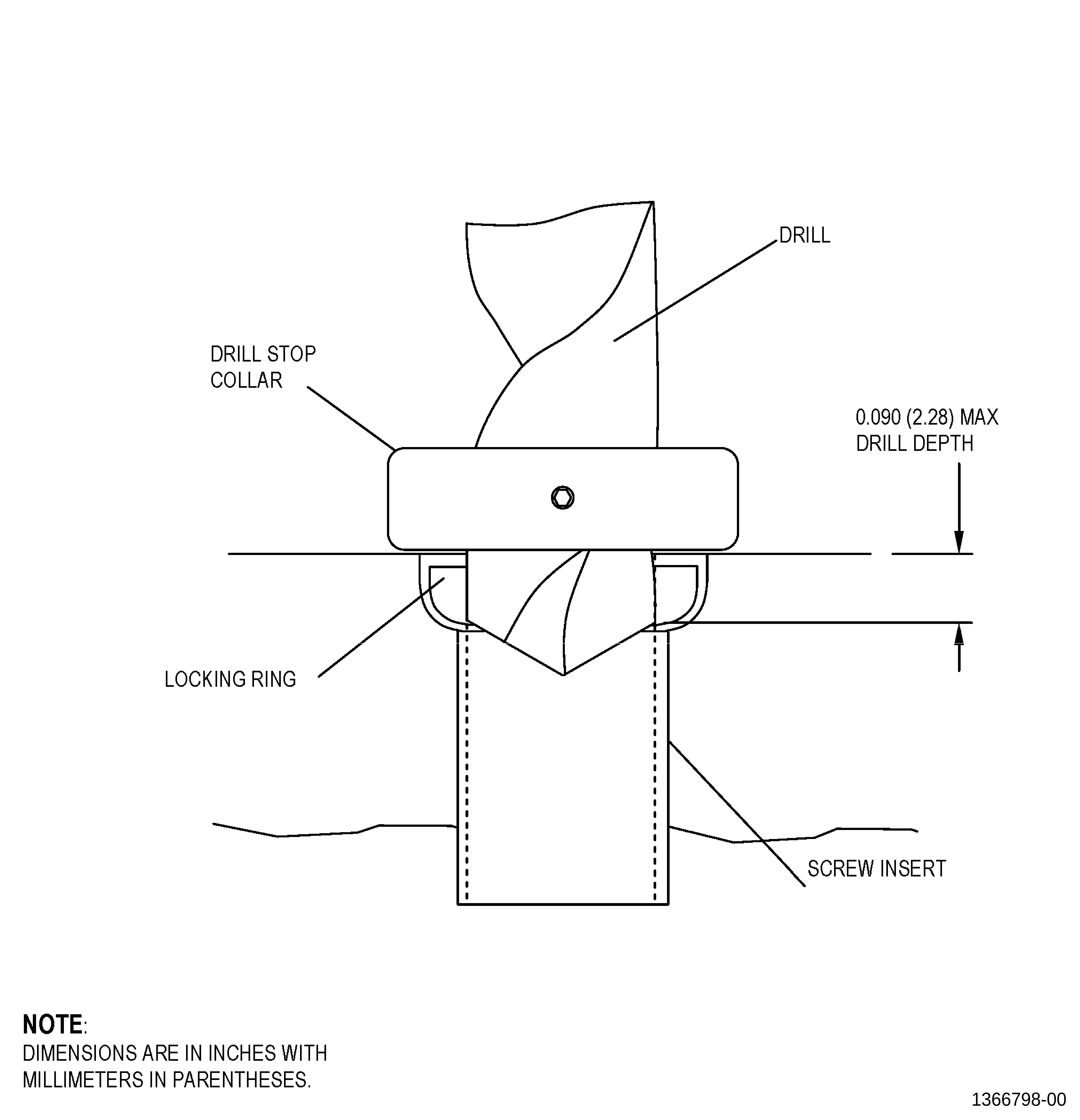
| (1) | Set-up the drill to drill a depth of0.090 inch (2.28 mm) or less as follows: |
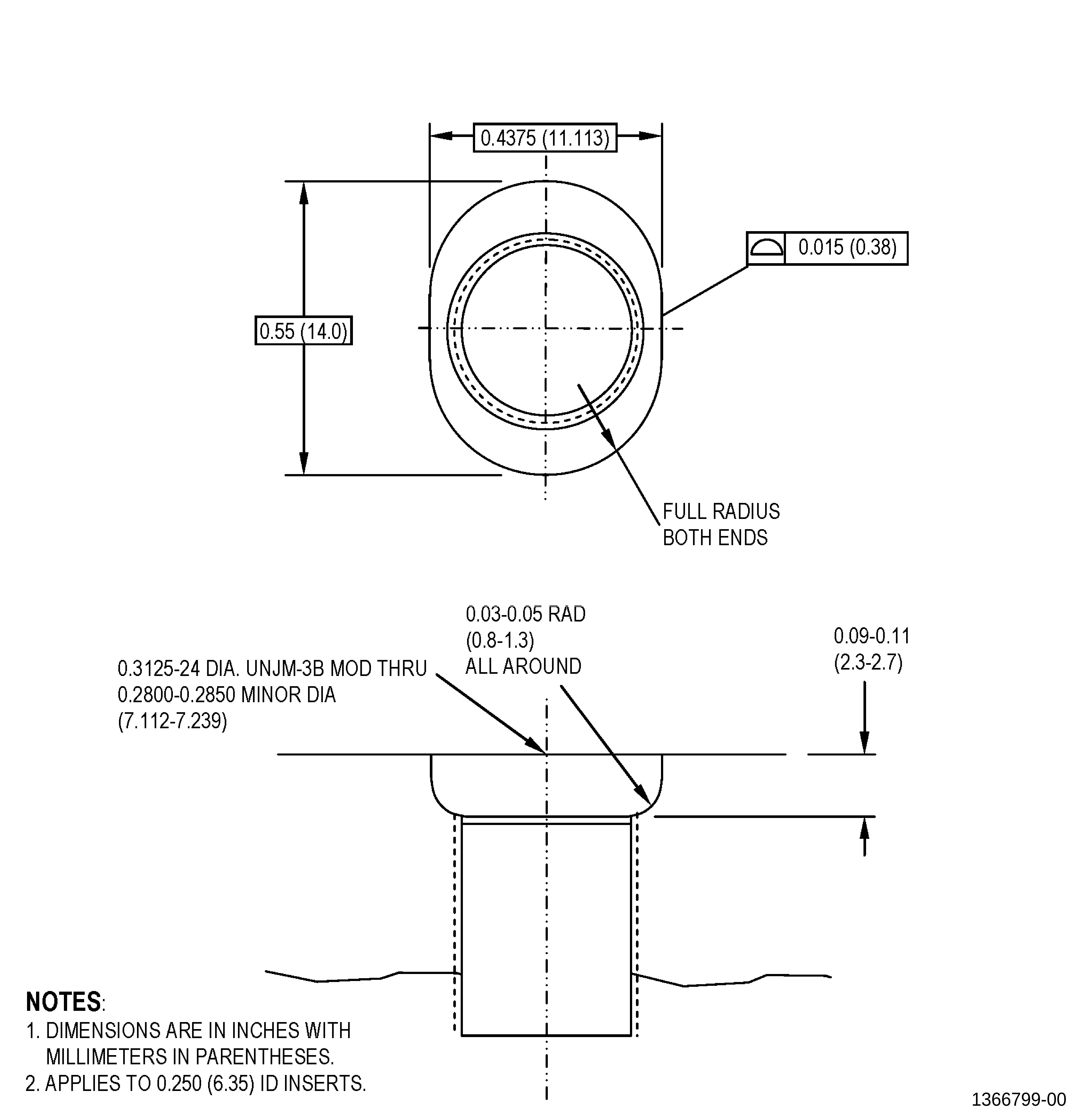
| (a) | For insert 1693M83P04 , usea 0.3125 inch (7.938 mm) diameter drill. |
| NOTE: |
|
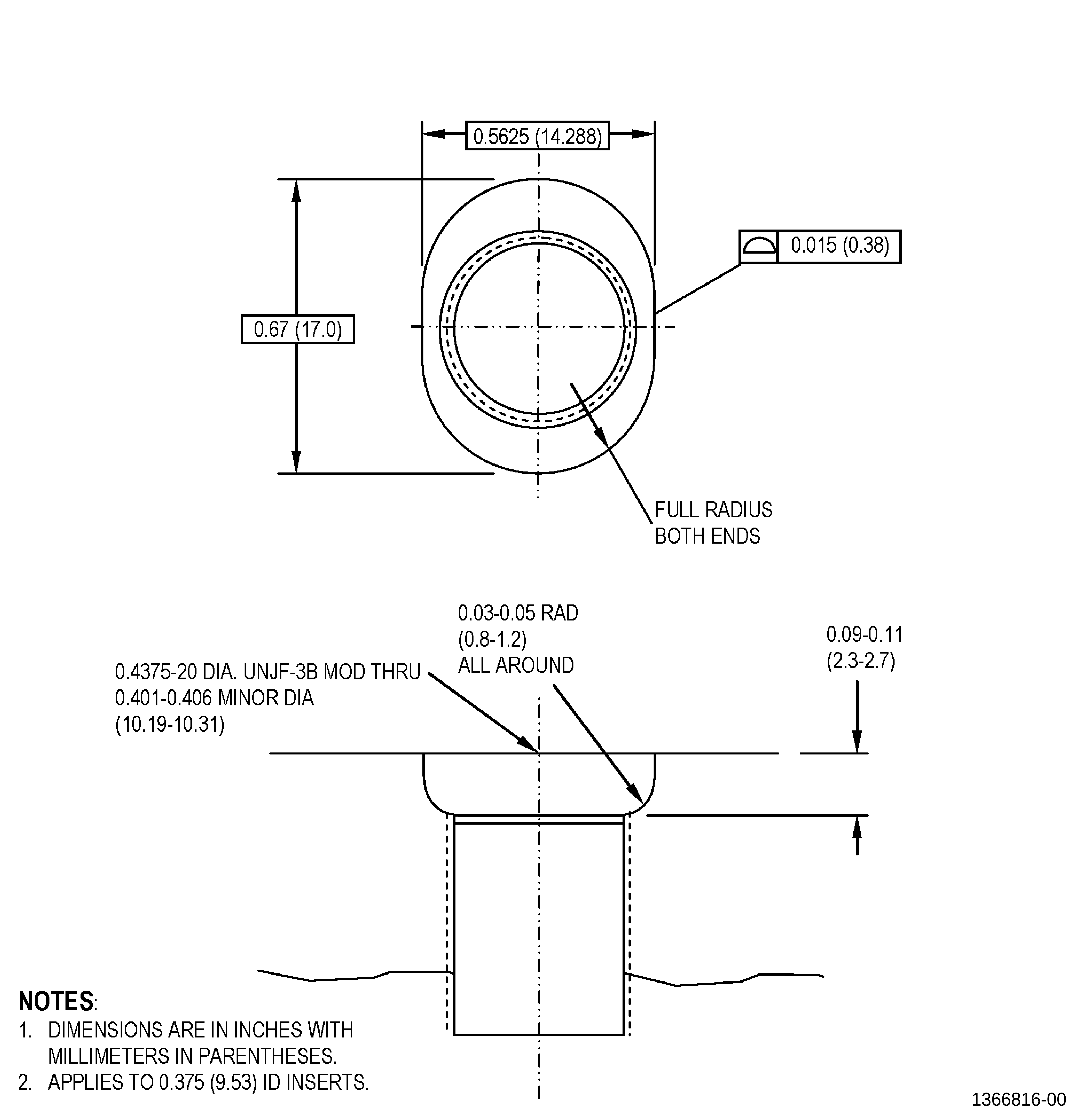
| (b) | For insert 1693M83P11 , 1693M83P12 , or 1693M83P14 , use a 0.375 inch (9.53 mm) diameterdrill. |
| (c) | Install a drill stop collar on thedrill. |
| (2) | Align the drill with the center-lineof the damaged insert. |
| Subtask 72-32-01-320-001 |
| WARNING: |
|
| CAUTION: |
|
| (3) | Drill into the insert 1693M83P04 , 1693M83P11 , 1693M83P12 , or 1693M83P14 to a depth, of 0.090 inch(2.28 mm) or less. |
| NOTE: |
|
| WARNING: |
|
| (4) | Use a pointed punch to remove the locking ring. |
| Subtask 72-32-01-350-004 |
| (5) | Use an allen key to remove the damagedinsert. |
| NOTE: |
|
| (6) | Remove all unwanted material from therepair area and forward case. |
| Subtask 72-32-01-220-067 |
| (7) | Do an inspection of the threads andcounterbore of the forward case repair area. Refer to Figure 903. |
| Subtask 72-32-01-350-005 |
| CAUTION: |
|
| C. | Install the new insert and locking ring in the forward case.Refer to AS3507, Installation and Removal of Thin Wall, Self-Locking,Short and Long Length Inserts, TASK 72-32-01-300-802 (paragraph 2.E.),SPD Information, Figure 903,and as follows: |
| (1) | Use insert 1693M83P04 for bosses. |
| (2) | Use insert 1693M83P11 , 1693M83P12 , or 1693M83P14 for the aft circumferential flange. |
| (3) | Install the new threaded insert intothe threaded hole of the forward case as follows: |
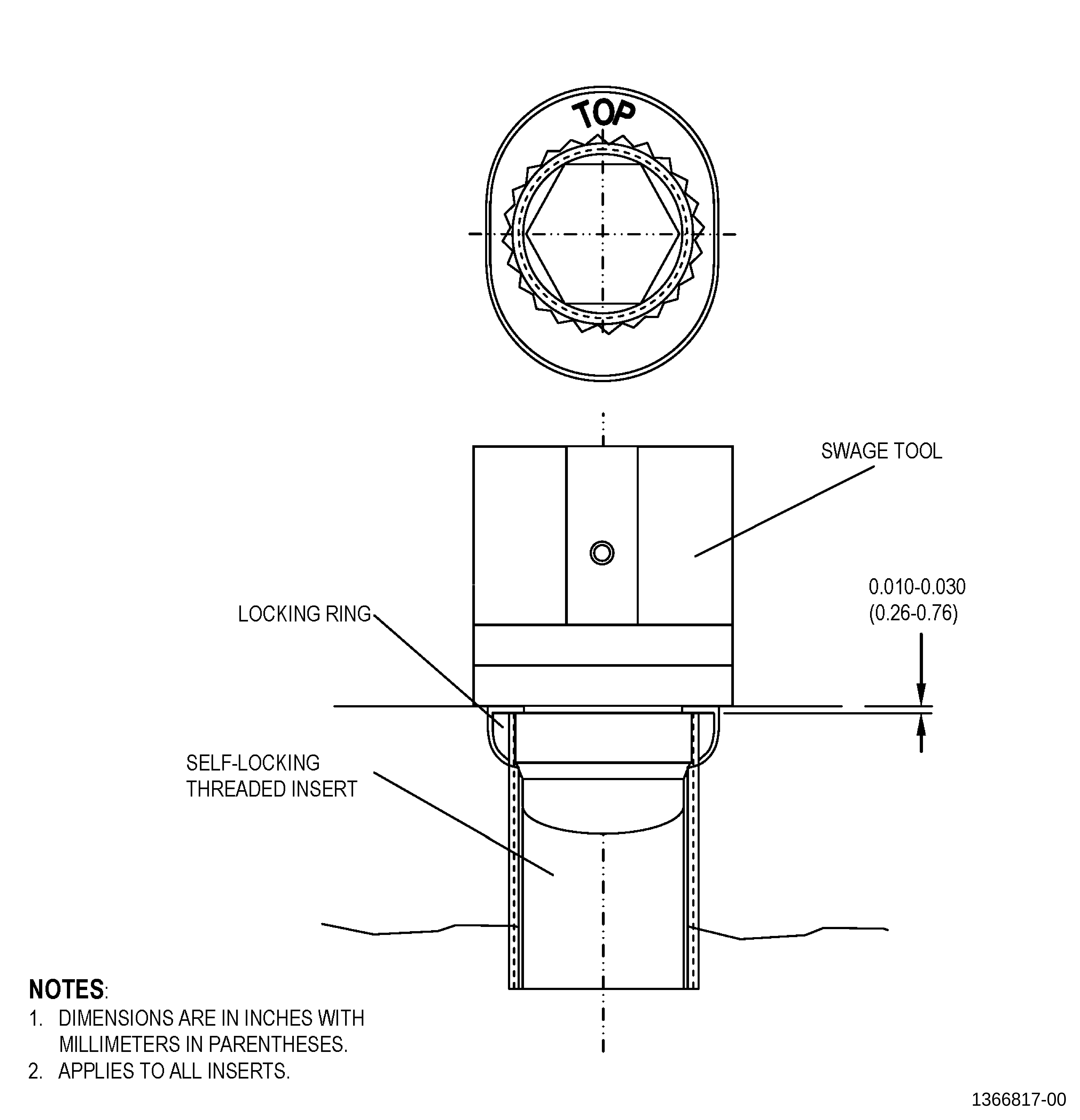
| (a) | Turn the insert until the top faceof the insert is 0.010-0.030 inch (0.25-0.76 mm) below the locationface surface of the forward case. |
| (4) | Install the new locking ring on theinsert and into the oval shaped hole as follows: |
| (a) | For insert 1693M83P04 , uselocking ring 1689M74P02 . |
| (b) | For insert 1693M83P11 , uselocking ring 1689M74P05 . |
| (c) | For insert 1693M83P14 , uselocking ring 1689M74P09 . |
| (d) | For insert 1693M83P12 , use locking ring 1689M74P07 . |
| (e) | The word TOP on the locking ring must face out fromthe forward case. |
| (5) | Swage the new insert into the lockingring as follows: |
| (a) | Installation of insert and ring-locking kits 738L579G03 and 738L579G04 require a reduced value of 0.032inch (0.81 mm) for dimension C (refer to table 4 of AS3507). |
| 1 | To achieve a reduced value of 0.032 inch (0.81 mm) fordimension C an additional 0.059 inch (1.50 mm) Nylon washer can berequired for the swage tool. |
| (b) | After swage of insert and ring-locking kits 738L579G03 and 738L579G04 , check dimension B (refer to table5 of AS3507) to a minimum depth, of 0.027 inch (0.69 mm). |
| Subtask 72-32-01-220-068 |
| D. | Do an inspection ofthe insert and locking ring. Refer to TASK 72-32-01-300-802 (paragraph 2.E.),SPD Information, and as follows: |
| (1) | Use 10X magnification. |
| (2) | Make sure that the insert serrationsare swaged into the serrations of the locking ring. |
| (3) | Make sure that the locking ring andinsert are below the surface of the forward case. |
| Subtask 72-32-01-350-006 |
| E. | Remove all the unwantedmaterial from the forward case repair area. |