| GENX-1B CLEANING,INSPECTION,AND REPAIR MANUAL | Dated: 01/31/2025 | |
| CIR 72-00-02 , INSPECTION 001 | ||
| PROPULSOR ASSEMBLY - INSPECTION | ||
| GENX-1B CLEANING,INSPECTION,AND REPAIR MANUAL | Dated: 01/31/2025 | |
| CIR 72-00-02 , INSPECTION 001 | ||
| PROPULSOR ASSEMBLY - INSPECTION | ||
| * * * FOR ALL |
| TASK 72-00-02-200-801 |
| 1 . | General. |
| A. | This procedure gives instructions to do an inspection of the propulsor assembly (0010C). Refer to Figure 801. You must do this inspection before you install: |
| • |
|
| • |
|
| • |
|
| B. | Any sub-assembly or part removed for access or limited workscope must be inspected in accordance with criteria in this section. If there is no criteria, the sub-assembly or part must receive a general visual inspection (GVI) for continued serviceability. Refer to TASK 72-00-00-200-805 (72-00-00, INSPECTION 001) . If required, the component can be hand-cleaned to do a visual inspection. Refer to TASK 70-21-01-110-001 (CLEANING METHOD 1 - SOLVENT DEGREASING) or TASK 70-21-03-160-001 (CLEANING METHOD 3 - STEAM CLEANING) . GVI can not be done to components identified in TASK 05-21-00-200-801 (05-21-00, LIFE LIMITS 001) that become piece part. These components must have their appropriate mandatory inspections done, unless stated differently in an applicable Service Bulletin. |
| C. | If you do this procedure and find unserviceable conditions for an assembly or part, refer to the applicable section of the engine manual for more disassembly and inspection procedures for the assembly or part. |
| D. | If you will fully disassemble the propulsor assembly, this procedure is not necessary. Refer to the applicable section of the engine manual for the inspection procedure for each part. |
| E. | The maintenance instructions in this Manual do not purport to cover all details or variations in equipment, nor do they provide for every possible contingency to be met in connection with installation, operation, maintenance, or GEAE certified repair facilities. The maintenance instructions are intended to be all-inclusive for a complete teardown and overhaul of the component or sub assembly. The individual procedures as written are one sequence based on General Electric experience. Alternate sequences to these maintenance instructions are at the discretion of the operator and/or overhaul shop provided the intent of the maintenance instructions is met. The operator and/or overhaul shop can select specific tasks to partially disassemble and assemble hardware or subassemblies based upon the on demand maintenance requirement of the individual engine work scope provided the final assembly configuration and requirements contained in the manual have been met. |
| F. | If an axisymmetric rotating part with a visible crack through the axial or radial thickness of the part feature is found during the inspection procedure, then the mating Life Limited Part(s) (LLP) can be affected. The mating LLP must be considered not serviceable and not repairable. |
| NOTE: |
|
| NOTE: |
|
| 2 . | Tools, Equipment, and Materials. |
| NOTE: |
|
| A. | Tools and Equipment. |
| (1) | Special Tools. None. |
| (2) | Standard Tools and Equipment. None. |
| (3) | Locally Manufactured Tools. None. |
| B. | Consumable Materials. None. |
| C. | Referenced Procedures. |
| D. | Expendable Parts. None. |
| 3 . | Specific Inspection Procedure. |
| Subtask 72-00-02-230-001 |
| A. | If the visual inspection or other conditions make it necessary, do a spot-fluorescent penetrant inspection. Refer to TASK 70-32-03-230-002 (SPOT-FLUORESCENT-PENETRANT INSPECTION). |
| 4 . | Visual Inspection. |
| Subtask 72-00-02-220-001 |
| A. | Do an inspection of all visible areas of the stage 1 fan disk (fan disk) (830A0) of the fan booster assembly (80000) as follows. Refer to Figure 801 and Figure 802. |
| (1) | Cracks: |
| Maximum serviceable limit: |
|
| Repair method: |
|
| Subtask 72-00-02-220-099 |
| (2) | Discoloration that is a result of a shotpeen procedure (rust color): |
| Maximum serviceable limit: |
|
| Repair method |
|
| Subtask 72-00-02-220-100 |
| (3) | Nicks, dents, and scratches (this does not include the retainer grooves or web areas): |
| Maximum serviceable limit: |
|
| Repair method: |
|
| Subtask 72-00-02-220-200 |
| (4) | Nicks, dents, and scratches in area B (do not include the web areas). Refer to Figure 802. |
| Maximum serviceable limit: |
|
| Repair method: |
|
| Subtask 72-00-02-220-101 |
| (5) | Nicks, dents, and scratches in the web areas: |
| Maximum serviceable limit: |
|
| Repair method: |
|
| Subtask 72-00-02-220-102 |
| (6) | Nicks, dents, scratches, and fretting (in the retainer grooves only): |
| Maximum serviceable limit: |
|
| Repair method: |
|
| Subtask 72-00-02-220-002 |
| B. | Do an inspection of the boltholes in the spinner flange of the fan disk (830A0) as follows. Refer to Figure 802. |
| (1) | Cracks: |
| Maximum serviceable limit: |
|
| Repair method: |
|
| Subtask 72-00-02-220-003 |
| (2) | Galling and scratches: |
| Maximum serviceable limit: |
|
| Repair method: |
|
| Subtask 72-00-02-220-004 |
| C. | Do an inspection of the dovetail slots of the fan disk (830A0) as follows. Refer to Figure 802. |
| (1) | Nicks, dents, scratches, and fretting on the pressure faces: |
| Maximum serviceable limit: |
|
| Repair method: |
|
| Subtask 72-00-02-220-103 |
| (2) | Nicks, dents, scratches, and fretting on the radius below and adjacent to the pressure faces: |
| Maximum serviceable limit: |
|
| Repair method: |
|
| Subtask 72-00-02-220-104 |
| (3) | Nicks, dents, scratches, and fretting on the bottom of the dovetail slots: |
| Maximum serviceable limit: |
|
| Repair method: |
|
| Subtask 72-00-02-220-201 |
| (4) | Foreign material embedment on the bottom of the dovetail slot bottom from the contact with fan blade spacer wear strip: |
| NOTE: |
|
| Maximum serviceable limit: |
|
| Repair method: |
|
| Subtask 72-00-02-220-105 |
| (5) | Nicks, dents, and scratches on the corners of the leading and trailing edges of the dovetail: |
| Maximum serviceable limit: |
|
| Repair method: |
|
| Subtask 72-00-02-220-005 |
| D. | Do an inspection of the flanges and mating faces of the fan disk (830A0) as follows. Refer to Figure 802. |
| (1) | Cracks: |
| Maximum serviceable limit: |
|
| Repair method: |
|
| Subtask 72-00-02-220-006 |
| (2) | Nicks, dents, and scratches: |
| Maximum serviceable limit: |
|
| Repair method: |
|
| Subtask 72-00-02-220-007 |
| (3) | Fretting: |
| Maximum serviceable limit: |
|
| Repair method: |
|
| Subtask 72-00-02-220-009 |
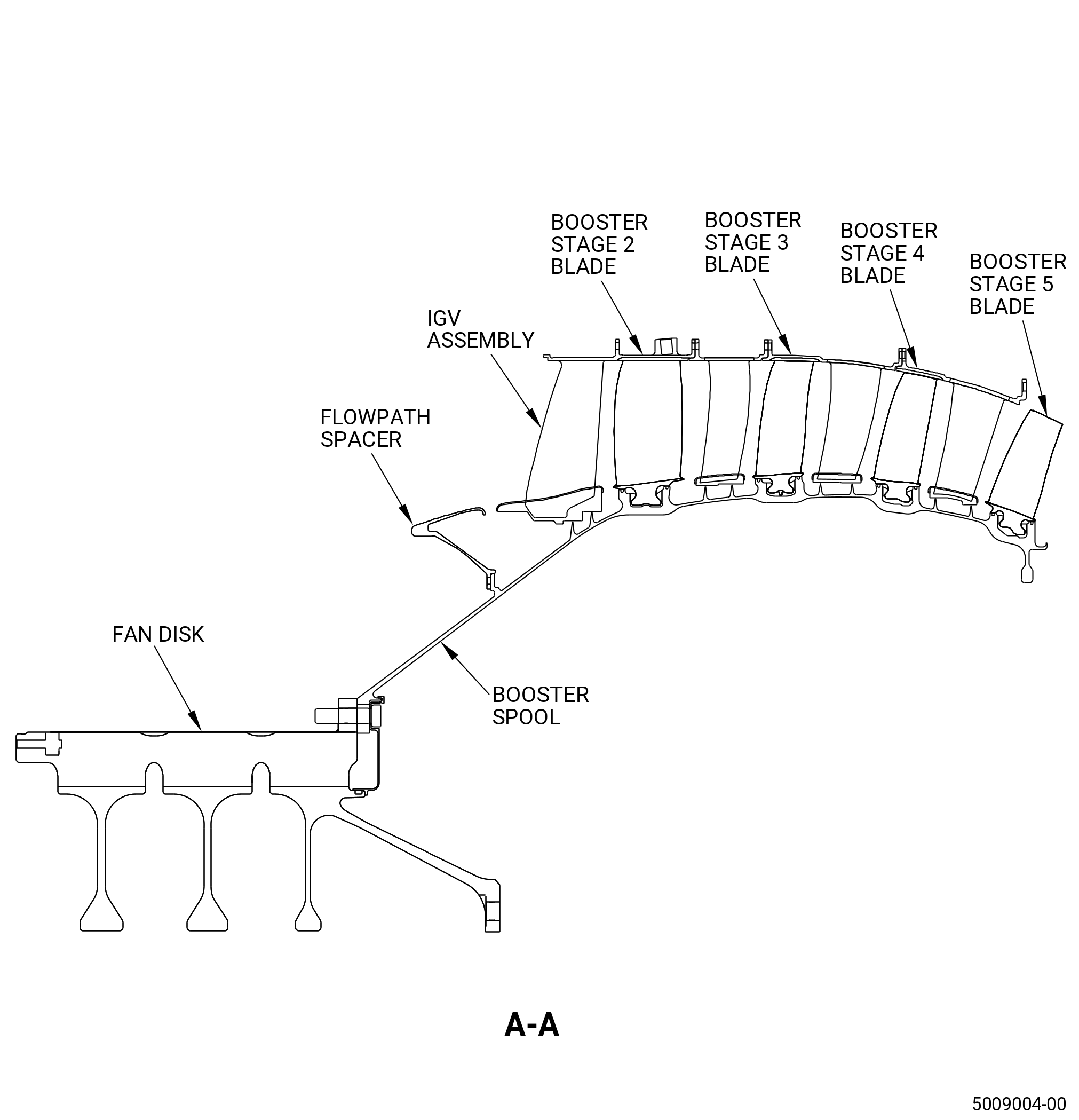
| E. | Do an inspection of areas of the booster spool (830AH) that you can see as follows. Refer to Figure 803. |
| (1) | Cracks: |
| Maximum serviceable limit: |
|
| Repair method: |
|
| Subtask 72-00-02-220-011 |
| F. | Do an inspection of all visible areas of the flowpath spacer (830AM) (this does not include area AA and the booster spool mounting flange) as follows. Refer to Figure 803 and Figure 805. |
| (1) | Cracks: |
| Maximum serviceable limit: |
|
| Repair method: |
|
| Subtask 72-00-02-220-185 |
| (2) | Nick, Dents, Scratches, and Pits: |
| Maximum serviceable limit: |
|
| Repair method: |
|
| Subtask 72-00-02-220-013 |
| G. | Do an inspection of Area AA that you can see on the flowpath spacer (830AM) as follows. Refer to Figure 805. |
| (1) | Nicks, dents, scratches, and pits: |
| Maximum serviceable limit: |
|
| Repair method: |
|
| Subtask 72-00-02-220-186 |
| (2) | Fretting and wear: |
| Maximum serviceable limit: |
|
| Maximum repairable limit |
|
| Repair method: |
|
| Subtask 72-00-02-220-202 |
| G.A. | Do an inspection of area F of the flowpath spacers (01-060 , 72-22-00) (SIN 830AM). Refer to Figure 818. |
| (1) | Erosion in the glass fiber erosion layer or carbon fiber layer: |
| Maximum serviceable limit: |
|
| Repair method: |
|
| Subtask 72-00-02-220-203 |
| (2) | Gouges, cuts, or scratches in the glass fiber erosion layer: |
| Maximum serviceable limit: |
|
| Repair method: |
|
| Subtask 72-00-02-220-018 |
| H. | Do an inspection of area AA of the inlet guide vane (vane) assembly (837A0) as follows. Refer to Figure 806. |
| (1) | Cracks: |
| Maximum serviceable limit: |
|
| Repair method: |
|
| Subtask 72-00-02-220-106 |
| (2) | Nicks and dents: |
| Maximum serviceable limit: |
|
| Repair method: |
|
| Subtask 72-00-02-220-107 |
| (3) | Scratches: |
| Maximum serviceable limit: |
|
| Repair method: |
|
| Subtask 72-00-02-220-019 |
| I. | Do an inspection of area BA of the vane assembly (837A0) as follows. Refer to Figure 806. |
| (1) | Cracks: |
| Maximum serviceable limit: |
|
| Repair method: |
|
| Subtask 72-00-02-220-108 |
| (2) | Nicks and dents: |
| Maximum serviceable limit: |
|
| Maximum repairable limit: |
|
| Repair method: |
|
| Subtask 72-00-02-220-109 |
| (3) | Tears: |
| Maximum serviceable limit: |
|
| Repair method: |
|
| Subtask 72-00-02-220-110 |
| (4) | Local distortion: |
| Maximum serviceable limit: |
|
| Repair method: |
|
| Subtask 72-00-02-220-111 |
| (5) | Scratches: |
| Maximum serviceable limit: |
|
| Maximum repairable limit: |
|
| Repair method: |
|
| Subtask 72-00-02-220-098 |
| J. | Do an inspection of area CA of the vane assembly (837A0) as follows. Refer to Figure 806. |
| (1) | Cracks: |
| Maximum serviceable limit: |
|
| Repair method: |
|
| Subtask 72-00-02-220-112 |
| (2) | Nicks and dents: |
| Maximum serviceable limit: |
|
| Repair method: |
|
| Subtask 72-00-02-220-113 |
| (3) | Tears: |
| Maximum serviceable limit: |
|
| Repair method: |
|
| Subtask 72-00-02-220-114 |
| (4) | Local distortion: |
| Maximum serviceable limit: |
|
| Repair method: |
|
| Subtask 72-00-02-220-115 |
| (5) | Scratches: |
| Maximum serviceable limit: |
|
| Repair method: |
|
| Subtask 72-00-02-220-020 |
| K. | Do an inspection of the outer shroud of the vane assembly (837A0) as follows. Refer to Figure 806. |
| (1) | Cracks: |
| Maximum serviceable limit: |
|
| Repair method: |
|
| Subtask 72-00-02-220-119 |
| (2) | Nicks, dents, and scratches on the forward ledge: |
| Maximum serviceable limit: |
|
| Repair method: |
|
| Subtask 72-00-02-220-122 |
| (3) | Fretting on the forward ledges: |
| Maximum serviceable limit: |
|
| Repair method: |
|
| Subtask 72-00-02-220-123 |
| (4) | Damaged insert: |
| Maximum serviceable limit: |
|
| Maximum repairable limit: |
|
| Repair method: |
|
| Subtask 72-00-02-220-021 |
| L. | Do an inspection of the areas you can see on each of the booster stages 2 thru 5 blades (blades) as follows. Refer to Figure 803 and Figure 807. |
| (1) | Cracks or tears: |
| Maximum serviceable limit: |
|
| Repair method: |
|
| Subtask 72-00-02-220-022 |
| M. | Do an inspection of area A of each of the blades that you can see as follows. Refer to Figure 807. |
| (1) | Nicks and/or dents on concave or convex sides: |
| Maximum serviceable limit: |
|
| Repair method: |
|
| Subtask 72-00-02-220-136 |
| (2) | Nicks and/or dents on the leading edges: |
| Maximum serviceable limit: |
|
| Repair method: |
|
| Subtask 72-00-02-220-137 |
| (3) | Local distortion on the leading or trailing edges: |
| Maximum serviceable limit: |
|
| Repair method: |
|
| Subtask 72-00-02-220-138 |
| (4) | Scratches: |
| Maximum serviceable limit: |
|
| Repair method: |
|
| Subtask 72-00-02-220-023 |
| N. | Do an inspection of area B of each of the blades that you can see as follows. Refer to Figure 807. |
| (1) | Nicks and dents: |
| Maximum serviceable limit: |
|
| Repair method: |
|
| Subtask 72-00-02-220-139 |
| (2) | Scratches: |
| Maximum serviceable limit: |
|
| Repair method: |
|
| Subtask 72-00-02-220-140 |
| (3) | Tears (high metal): |
| Maximum serviceable limit: |
|
| Repair method: |
|
| Subtask 72-00-02-220-141 |
| (4) | Local distortion on the leading and/or trailing edge: |
| Maximum serviceable limit: |
|
| Repair method: |
|
| Subtask 72-00-02-220-142 |
| O. | Do an inspection of area D of each of the blades that can be seen as follows. Refer to Figure 807. |
| (1) | Missing blade tip corner: |
| Maximum serviceable limit: |
|
| Repair method: |
|
| Subtask 72-00-02-220-143 |
| (2) | Tip curl: |
| Maximum serviceable limit: |
|
| Repair method: |
|
| Subtask 72-00-02-220-196 |
| (3) | Nicks and dents: |
| Maximum serviceable limit: |
|
| Repair method: |
|
| Subtask 72-00-02-220-197 |
| (4) | Scratches: |
| Maximum serviceable limit: |
|
| Repair method: |
|
| Subtask 72-00-02-220-198 |
| (5) | Tears (high metal): |
| Maximum serviceable limit: |
|
| Repair method: |
|
| Subtask 72-00-02-220-024 |
| P. | Do an inspection of area C of each of the blades you can see as follows. Refer to Figure 807. |
| (1) | Nicks, dents, and scratches: |
| Maximum serviceable limit: |
|
| Repair method: |
|
| Subtask 72-00-02-220-025 |
| Q. | Do an inspection of each platform of the blades you can see as follows. Refer to Figure 807. |
| (1) | Nicks, dents, and scratches: |
| Maximum serviceable limit: |
|
| Repair method: |
|
| Subtask 72-00-02-220-026 |
| (2) | Rub marks on edge: |
| Maximum serviceable limit: |
|
| Repair method: |
|
| Subtask 72-00-02-220-031 |
| R. | Do an inspection of the fan hub frame assembly (84000) as follows. |
| (1) | Cracks: |
| Maximum serviceable limit: |
|
| Repair method: |
|
| Subtask 72-00-02-220-144 |
| (2) | Dents: |
| Maximum serviceable limit: |
|
| Repair method: |
|
| Subtask 72-00-02-220-145 |
| (3) | Cracks in the webs of the clevis on the thrust link: |
| Maximum serviceable limit: |
|
| Repair method: |
|
| Subtask 72-00-02-220-146 |
| (4) | Cracks in the clevis bosses of the thrust link: |
| Maximum serviceable limit: |
|
| Repair method: |
|
| Subtask 72-00-02-220-032 |
| (5) | Nicks, scratches, and gouges in the engine mount bosses and webs: |
| Maximum serviceable limit: |
|
| Maximum repairable limit: |
|
| Repair method: |
|
| Subtask 72-00-02-220-033 |
| (6) | Missing locking feature in each threaded insert: |
| Maximum serviceable limit: |
|
| Maximum repairable limit: |
|
| Repair method: |
|
| Subtask 72-00-02-220-147 |
| (7) | Damaged threads on each threaded insert: |
| Maximum serviceable limit: |
|
| Maximum repairable limit: |
|
| Repair method: |
|
| Subtask 72-00-02-220-148 |
| (8) | Damaged threads on each stud: |
| Maximum serviceable limit: |
|
| Maximum repairable limit: |
|
| Repair method: |
|
| Subtask 72-00-02-220-035 |
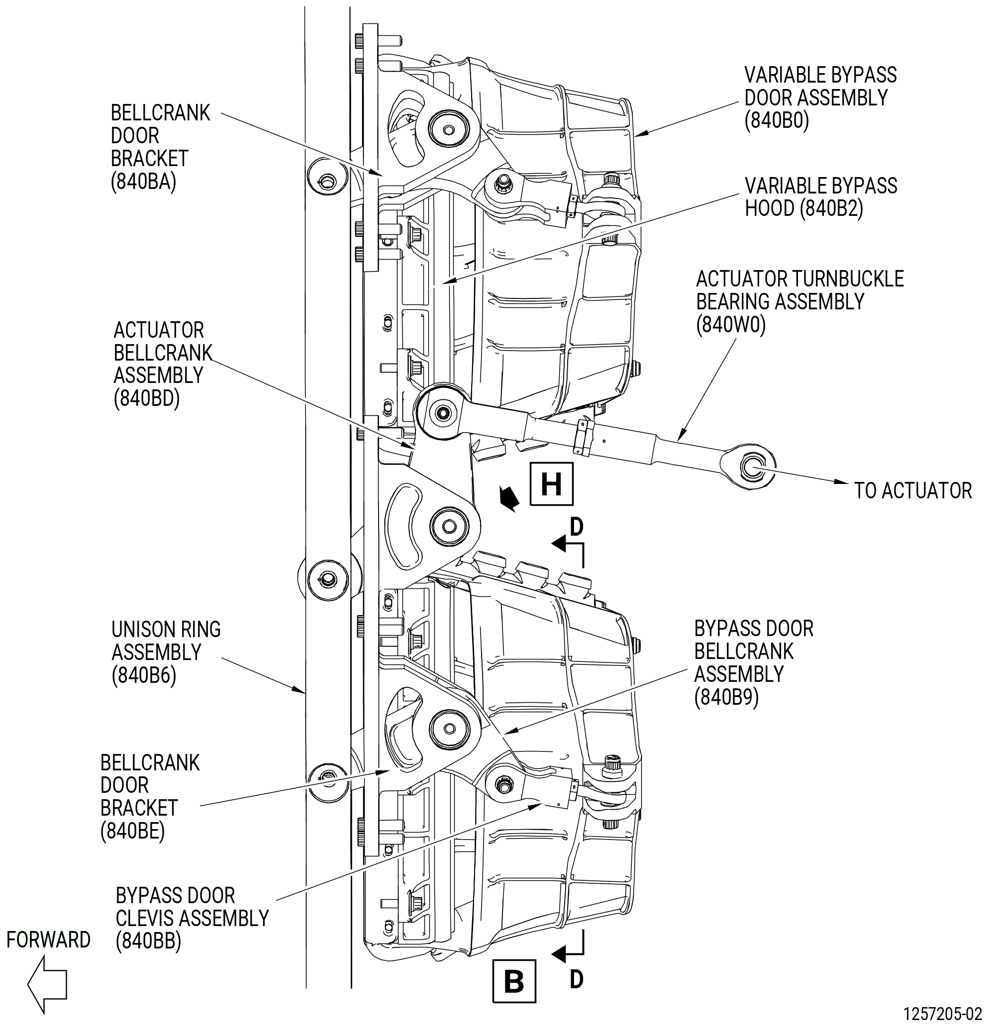
| S. | Do an inspection of each variable bypass door (door) (840B0) as follows. |
| (1) | Cracks in the body of the door: |
| Maximum serviceable limit: |
|
| Repair method: |
|
| Subtask 72-00-02-220-036 |
| (2) | Nicks and scratches: |
| Maximum serviceable limit: |
|
| Repair method: |
|
| Subtask 72-00-02-220-038 |
| T. | Do an inspection of each variable bypass hood (hood) (840B2) as follows. |
| (1) | Tears and holes in the seal: |
| Maximum serviceable limit: |
|
| Repair method: |
|
| Subtask 72-00-02-220-159 |
| (2) | cracks: |
| Maximum serviceable limit: |
|
| Repair method: |
|
| Subtask 72-00-02-220-150 |
| (3) | Frayed edges: |
| Maximum serviceable limit: |
|
| Repair method: |
|
| Subtask 72-00-02-220-151 |
| (4) | Disbonded seals: |
| Maximum serviceable limit: |
|
| Repair method: |
|
| Subtask 72-00-02-220-039 |
| U. | Do an inspection of each actuator bellcrank (bellcrank) (840BD) and each bypass door bellcrank (bellcrank) (840B9) as follows. |
| (1) | Cracks: |
| Maximum serviceable limit: |
|
| Repair method: |
|
| Subtask 72-00-02-220-040 |
| (2) | Nicks and scratches on the bellcrank (840B9): |
| Maximum serviceable limit: |
|
| Maximum repairable limit: |
|
| Repair method: |
|
| Subtask 72-00-02-220-041 |
| (3) | Nicks and scratches on the bellcrank (840BD): |
| Maximum serviceable limit: |
|
| Maximum repairable limit: |
|
| Repair method: |
|
| Subtask 72-00-02-220-042 |
| (4) | Loose bearing: |
| Maximum serviceable limit: |
|
| Repair method: |
|
| Subtask 72-00-02-220-187 |
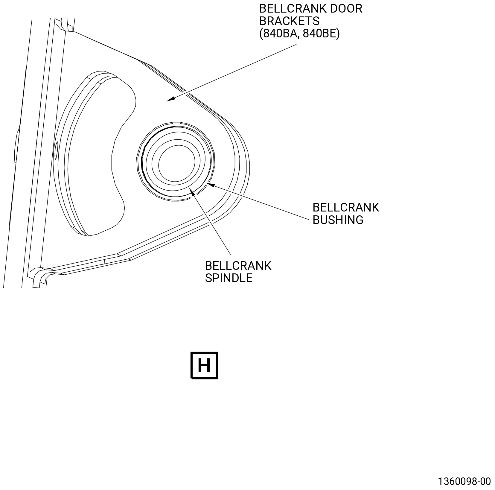
| V. | Do an inspection of the bellcrank door bracket assembly (840BA) as follows. Refer to Figure 808. |
| NOTE: |
|
| (1) | Cracks: |
| Maximum serviceable limit: |
|
| Repair method: |
|
| Subtask 72-00-02-220-188 |
| (2) | Worn bushings: |
| Maximum serviceable limit: |
|
| Repair method: |
|
| Subtask 72-00-02-220-043 |
| W. | Do an inspection of each rod end plain bearing (bearing) (840BC) as follows. |
| (1) | Loose bearings: |
| Maximum serviceable limit: |
|
| Repair method: |
|
| Subtask 72-00-02-220-044 |
| X. | Do an inspection of the unison ring (840B6) as follows. |
| (1) | Cracks: |
| Maximum serviceable limit: |
|
| Repair method: |
|
| Subtask 72-00-02-220-045 |
| (2) | Nicks, dents, and scratches: |
| Maximum serviceable limit: |
|
| Maximum repairable limit: |
|
| Repair method: |
|
| Subtask 72-00-02-220-048 |
| Y. | Do an inspection of each actuator clevis (840B7) and bypass door clevis (840BB) as follows. |
| (1) | Cracks: |
| Maximum serviceable limit: |
|
| Repair method: |
|
| Subtask 72-00-02-220-049 |
| (2) | Nicks and scratches: |
| Maximum serviceable limit: |
|
| Maximum repairable limit: |
|
| Repair method: |
|
| Subtask 72-00-02-220-050 |
| (3) | Inserts that are loose, missing, or have damaged threads: |
| Maximum serviceable limit: |
|
| Maximum repairable limit: |
|
| Repair method: |
|
| Subtask 72-00-02-220-189 |
| Z. | Do an inspection of each IGV bridge connector (071E0) as follows. |
| (1) | Cracks: |
| Maximum serviceable limit: |
|
| Repair method: |
|
| Subtask 72-00-02-220-190 |
| (2) | Nicks, dents, and scratches: |
| Maximum serviceable limit: |
|
| Maximum repairable limit: |
|
| Repair method: |
|
| Subtask 72-00-02-220-051 |
| CAUTION: |
|
| AA. | Do an inspection of all areas of each IGV arm (071D0) as follows. Refer to Figure 809. |
| (1) | Cracks: |
| Maximum serviceable limit: |
|
| Repair method: |
|
| Subtask 72-00-02-220-153 |
| (2) | Distortion: |
| Maximum serviceable limit: |
|
| Repair method: |
|
| Subtask 72-00-02-220-160 |
| (3) | Nicks, dents, and scratches on the external contour of the lever arm (areas G and H): |
| Maximum serviceable limit: |
|
| Maximum repairable limit: |
|
| Repair method: |
|
| Subtask 72-00-02-220-052 |
| AB. | Do an inspection of each pin on the IGV arms (071D0) as follows. |
| (1) | Distortion: |
| Maximum serviceable limit: |
|
| Repair method: |
|
| Subtask 72-00-02-220-154 |
| (2) | Looseness of the heads: |
| Maximum serviceable limit: |
|
| Repair method: |
|
| Subtask 72-00-02-220-164 |
| AC. | Do an inspection of each IGV actuating ring (071A0, 071A5) as follows. Refer to Figure 810. |
| (1) | Cracks: |
| Maximum serviceable limit: |
|
| Repair method: |
|
| Subtask 72-00-02-220-165 |
| (2) | Nicks and scratches: |
| Maximum serviceable limit: |
|
| Maximum repairable limit: |
|
| Repair method: |
|
| Subtask 72-00-02-220-166 |
| (3) | Distortion (bent or twisted): |
| Maximum serviceable limit: |
|
| Repair method: |
|
| Subtask 72-00-02-220-167 |
| (4) | Spacer button wear: |
| Maximum serviceable limit: |
|
| Repair method: |
|
| Subtask 72-00-02-220-053 |
| AD. | Do an inspection of each variable bypass door seal (door seal) (840N0) as follows. |
| (1) | Tears and holes in the door seal: |
| Maximum serviceable limit: |
|
| Repair method: |
|
| Subtask 72-00-02-220-156 |
| (2) | Cracks: |
| Maximum serviceable limit: |
|
| Repair method: |
|
| Subtask 72-00-02-220-157 |
| (3) | Frayed edges: |
| Maximum serviceable limit: |
|
| Repair method: |
|
| Subtask 72-00-02-220-158 |
| (4) | Disbonded seals: |
| Maximum serviceable limit: |
|
| Repair method: |
|
| Subtask 72-00-02-220-054 |
| AE. | Do an inspection of the HPC stator forward case assembly (forward case assembly) (073A0) of the HPC assembly (00108) as follows. Refer to Figure 801 and Figure 811. |
| (1) | Cracks in the outer surface (skin): |
| Maximum serviceable limit: |
|
| Repair method: |
|
| Subtask 72-00-02-220-056 |
| (2) | Cracks in the horizontal and circumferential flanges: |
| Maximum serviceable limit: |
|
| Repair method: |
|
| Subtask 72-00-02-220-057 |
| (3) | Loose, broken, or missing nuts and bolts: |
| Maximum serviceable limit: |
|
| Repair method: |
|
| Subtask 72-00-02-220-058 |
| (4) | Discoloration (hot spots) on all surfaces: |
| Maximum serviceable limit: |
|
| Repair method: |
|
| Subtask 72-00-02-220-194 |
| (5) | Damaged insert threads on the mounting pads or bosses: |
| Maximum serviceable limit: |
|
| Repair method: |
|
| Subtask 72-00-02-220-193 |
| AF. | Do an inspection of the machine bolts (bolt) (07320) in the unused forward case assembly mounting bosses (case bosses) as follows. Refer to Figure 811. |
| (1) | Loose, broken, or missing bolts in case bosses: |
| Maximum serviceable limit: |
|
| Maximum repairable limit: |
|
| Repair method: |
|
| Subtask 72-00-02-220-195 |
| (2) | Damaged insert threads on the bosses: |
| Maximum serviceable limit: |
|
| Repair method: |
|
| Subtask 72-00-02-220-059 |
| AG. | Do an inspection of the HPC stator extension case (extension case) (080AL) as follows. Refer to Figure 812. |
| (1) | Nicks, pits, scores, and scratches on all surfaces: |
| Maximum serviceable limit: |
|
| Maximum repairable limit: |
|
| Repair method: |
|
| Subtask 72-00-02-220-199 |
| (2) | Damaged threads on the mounting pads: |
| Maximum serviceable limit: |
|
| Repair method: |
|
| Subtask 72-00-02-220-060 |
| CAUTION: |
|
| AH. | Do an inspection of all areas of each of the variable stator vane (VSV) stages 1-4 lever arms (lever arms) (071D1, 071D2, 071D3, 071D4, 071D6, 071D7, 071D8, 071D9) as follows. Refer to Figure 801. |
| (1) | Cracks: |
| Maximum serviceable limit: |
|
| Repair method: |
|
| Subtask 72-00-02-220-061 |
| (2) | Distortion: |
| Maximum serviceable limit: |
|
| Repair method: |
|
| Subtask 72-00-02-220-062 |
| (3) | Nicks, dents, and scratches in area H: |
| Maximum serviceable limit: |
|
| Maximum repairable limit: |
|
| Repair method: |
|
| Subtask 72-00-02-220-063 |
| (4) | Nicks, dents, and scratches in area G for lever arms (071D1, 071D2, 071D3, 071D6, 071D7, 071D8): |
| Maximum serviceable limit: |
|
| Maximum repairable limit: |
|
| Repair method: |
|
| Subtask 72-00-02-220-161 |
| (5) | Nicks, dents, and scratches in area G for lever arms (071D4, 071D9): |
| Maximum serviceable limit: |
|
| Maximum repairable limit: |
|
| Repair method: |
|
| Subtask 72-00-02-220-064 |
| AI. | Do an inspection of the pin of each lever arm (071D0, 071D1, 071D2, 071D3, 071D4, 071D6, 071D7, 071D8, 071D9) as follows. Refer to Figure 801. |
| (1) | Distortion: |
| Maximum serviceable limit: |
|
| Repair method: |
|
| Subtask 72-00-02-220-065 |
| (2) | Looseness of the formed heads: |
| Maximum serviceable limit: |
|
| Repair method: |
|
| Subtask 72-00-02-220-067 |
| CAUTION: |
|
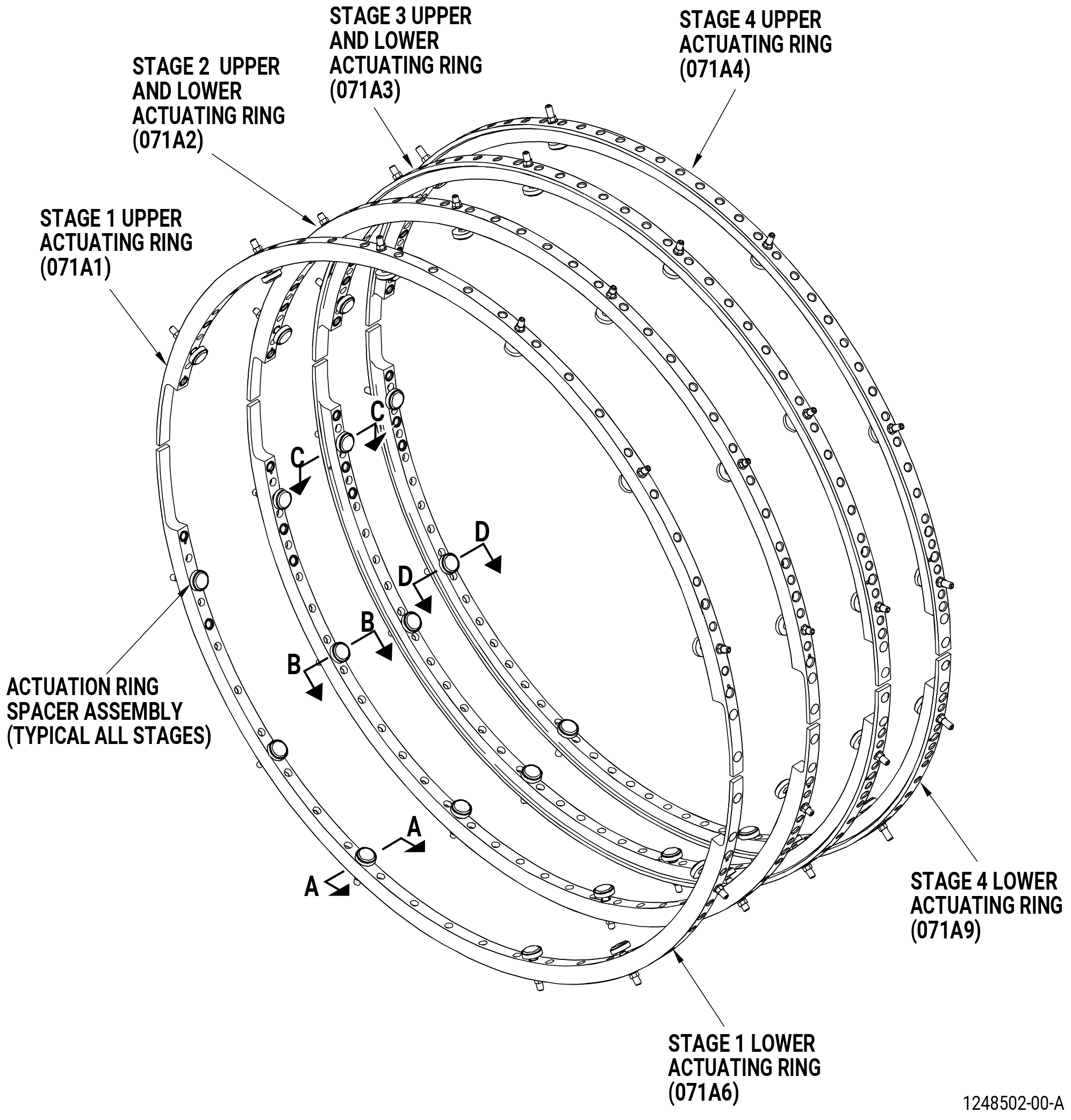
| AJ. | Do an inspection of all areas of each of the upper and lower VSV stages 1-4 actuating rings (actuating rings) (071A1, 071A2, 071A3, 071A4, 071A6, 071A9) as follows. Refer to Figure 813. |
| (1) | Cracks: |
| Maximum serviceable limit: |
|
| Repair method: |
|
| Subtask 72-00-02-220-068 |
| (2) | Distortion (twisting or bending): |
| Maximum serviceable limit: |
|
| Repair method: |
|
| Subtask 72-00-02-220-069 |
| (3) | Scratches: |
| Maximum serviceable limit: |
|
| Maximum repairable limit: |
|
| Repair method: |
|
| Subtask 72-00-02-220-070 |
| (4) | Nicks and dents: |
| Maximum serviceable limit: |
|
| Maximum repairable limit: |
|
| Repair method: |
|
| Subtask 72-00-02-220-181 |
| (5) | Spacer button wear (Stage 1) (071A1, 071A6): |
| Maximum serviceable limit: |
|
| Maximum repairable limit |
|
| Repair method: |
|
| Subtask 72-00-02-220-182 |
| (6) | Spacer button wear (Stage 2) (071A2): |
| Maximum serviceable limit: |
|
| Maximum repairable limit |
|
| Repair method: |
|
| Subtask 72-00-02-220-183 |
| (7) | Spacer button wear (Stage 3) (071A3): |
| Maximum serviceable limit: |
|
| Maximum repairable limit |
|
| Repair method: |
|
| Subtask 72-00-02-220-184 |
| (8) | Spacer button wear (Stage 4) (071A4, 071A9): |
| Maximum serviceable limit: |
|
| Maximum repairable limit |
|
| Repair method: |
|
| Subtask 72-00-02-220-071 |
| AK. | Do an inspection of each lever pin bushing (bushing) (071TB) of the actuating rings as follows. Refer to Figure 801. |
| (1) | Broken or worn bushing: |
| Maximum serviceable limit: |
|
| Repair method: |
|
| Subtask 72-00-02-220-072 |
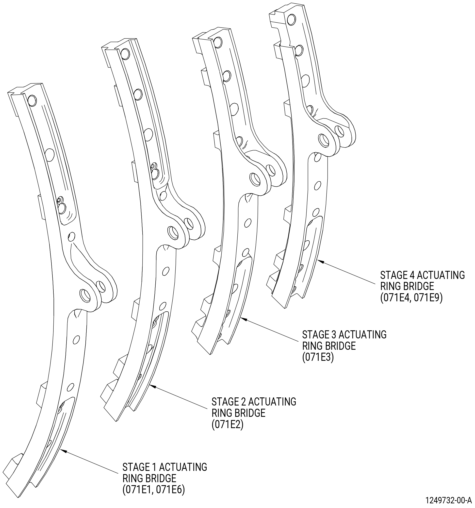
| AL. | Do an inspection of each of the VSV stages 1-4 bridges (bridges) (071D1, 071D2, 071D3, 071D4, 071D6, 071D9) on the actuating rings as follows. Refer to Figure 801. |
| (1) | Cracks and breaks: |
| Maximum serviceable limit: |
|
| Repair method: |
|
| Subtask 72-00-02-220-073 |
| CAUTION: |
|
| AM. | Do an inspection of each torque shaft (2322M67) as follows. Refer to Figure 801. |
| (1) | Cracks: |
| Maximum serviceable limit: |
|
| Repair method: |
|
| Subtask 72-00-02-220-074 |
| (2) | Nicks, dents, and scratches: |
| Maximum serviceable limit: |
|
| Maximum repairable limit: |
|
| Repair method: |
|
| Subtask 72-00-02-220-075 |
| CAUTION: |
|
| AN. | Do an inspection of each of the VSV stages 1-4 turnbuckles (turnbuckles) as follows. Refer to Figure 801. |
| (1) | Cracks: |
| Maximum serviceable limit: |
|
| Repair method: |
|
| Subtask 72-00-02-220-076 |
| (2) | Nicks, dents, scores, scratches, and pits: |
| Maximum serviceable limit: |
|
| Maximum repairable limit: |
|
| Repair method: |
|
| Subtask 72-00-02-220-077 |
| CAUTION: |
|
| AO. | Do an inspection of each spherical bearing of the turnbuckles as follows. Refer to Figure 801. |
| (1) | Looseness of the ball race: |
| Maximum serviceable limit: |
|
| Repair method: |
|
| Subtask 72-00-02-220-078 |
| CAUTION: |
|
| AP. | Do an inspection of each VSV forward support (support) (2322M73) and VSV aft support (support) (2322M74) as follows. Refer to Figure 801. |
| (1) | Cracks: |
| Maximum serviceable limit: |
|
| Repair method: |
|
| Subtask 72-00-02-220-079 |
| (2) | Nicks, dents, scores, scratches, and pits: |
| Maximum serviceable limit: |
|
| Maximum repairable limit: |
|
| Repair method: |
|
| Subtask 72-00-02-220-080 |
| AQ. | Do an inspection of the outer surface of the combustion case (12001) of the CDN assembly (0010A) as follows. Refer to Figure 801 and Figure 814. |
| (1) | Cracks in the parent material: |
| Maximum serviceable limit: |
|
| Repair method: |
|
| Subtask 72-00-02-220-081 |
| (2) | Dents with a smooth contour: |
| Maximum serviceable limit: |
|
| Repair method: |
|
| Subtask 72-00-02-220-082 |
| (3) | Nicks, scores, and scratches: |
| Maximum serviceable limit: |
|
| Maximum repairable limit: |
|
| Repair method: |
|
| Subtask 72-00-02-220-083 |
| (4) | Discoloration: |
| Maximum serviceable limit: |
|
| Repair method: |
|
| Subtask 72-00-02-220-084 |
| (5) | Bulges: |
| Maximum serviceable limit: |
|
| Repair method: |
|
| Subtask 72-00-02-220-085 |
| (6) | Corrosion: |
| Maximum serviceable limit: |
|
| Repair method: |
|
| Subtask 72-00-02-220-086 |
| AR. | Do an inspection of the pads on the combustion case (12001) as follows. Refer to Figure 814. |
| (1) | Damaged threads on the pads (where LRUs are removed): |
| Maximum serviceable limit: |
|
| Maximum repairable limit: |
|
| Repair method: |
|
| Subtask 72-00-02-220-087 |
| (2) | Damaged threads in the inserts on the pads (where LRUs are removed): |
| Maximum serviceable limit: |
|
| Maximum repairable limit: |
|
| Repair method: |
|
| Subtask 72-00-02-220-089 |
| AS. | Do an inspection of all body surfaces of the HPT stator case (174B0) of the HPT stage 2 nozzle assembly (17400) as follows. Refer to Figure 801 and Figure 815. |
| (1) | Cracks: |
| Maximum serviceable limit: |
|
| Repair method: |
|
| Subtask 72-00-02-220-090 |
| (2) | Nicks and scratches: |
| Maximum serviceable limit: |
|
| Maximum repairable limit: |
|
| Repair method: |
|
| Subtask 72-00-02-220-091 |
| (3) | Nicks and scratches, more than 0.025 inch (0.64 mm) in depth: |
| Maximum serviceable limit: |
|
| Repair method: |
|
| Subtask 72-00-02-220-092 |
| (4) | Dents: |
| Maximum serviceable limit: |
|
| Repair method: |
|
| Subtask 72-00-02-220-093 |
| AT. | Do an inspection of the TCF case assembly (2304M98) of the TCF assembly (92500) as follows. Refer to Figure 801 and Figure 816. |
| (1) | Cracks in the outer case: |
| Maximum serviceable limit: |
|
| Repair method: |
|
| Subtask 72-00-02-220-095 |
| (2) | Radial cracks in the aft flange boltholes: |
| Maximum serviceable limit: |
|
| Repair method: |
|
| Subtask 72-00-02-220-096 |
| (3) | Nicks and gouges: |
| Maximum serviceable limit: |
|
| Maximum repairable limit: |
|
| Repair method: |
|
| Subtask 72-00-02-220-097 |
| (4) | Dents: |
| Maximum serviceable limit: |
|
| Repair method: |
|
| Subtask 72-00-02-220-191 |
| AU. | Remove the core module assembly to get access to the forward end of the HPC forward case (073A0). Refer to TASK 72-31-00-800-803 (72-31-00, SPECIAL PROCEDURE 002). Blisk removal is not required. Inspect the stage 1 rotor blade rub land for: |
| (1) | Nicks, dents, scratches, gouges, and grooves: |
| Maximum serviceable limit: |
|
| • |
|
| • |
|
| • |
|
| • |
|
| Repair method: |
|
| Subtask 72-00-02-220-192 |
| (2) | Dimension A at 24 equally distance locations. Refer to Figure 817. |
| Maximum serviceable limit: |
|
| Repair method: |
|
| 5 . | Dimensional Inspection |
| Subtask 72-00-02-220-162 |
| A. | Do an dimensional inspection of the IGV actuating ring (071A0, 071A5) spacer assembly as follows. Refer to Figure 810. |
| (1) | Dimension B (button): |
| Minimum serviceable limit: |
|
| Repair method: |
|
| Subtask 72-00-02-220-176 |
| (2) | Dimension C: |
| Maximum serviceable limit: |
|
| Maximum repairable limit: |
|
| Repair method: |
|
| Subtask 72-00-02-220-168 |
| B. | Do an dimensional inspection of the HPC stator stage 1 VSV actuating ring (071A1, 071A6) spacer assembly as follows. Refer to Figure 813. |
| (1) | Dimension E (button): |
| Minimum serviceable limit: |
|
| Repair method: |
|
| Subtask 72-00-02-220-177 |
| (2) | Dimension F: |
| Maximum serviceable limit: |
|
| Maximum repairable limit |
|
| Repair method: |
|
| Subtask 72-00-02-220-170 |
| C. | Do an dimensional inspection of the HPC stator stage 2 VSV actuating rings (071A2) as follows. Refer to Figure 813. |
| (1) | Dimension G (button): |
| Minimum serviceable limit: |
|
| Repair method: |
|
| Subtask 72-00-02-220-178 |
| (2) | Dimension H: |
| Maximum serviceable limit: |
|
| Maximum repairable limit |
|
| Repair method: |
|
| Subtask 72-00-02-220-172 |
| D. | Do an dimensional inspection of the HPC stator stage 3 VSV actuating rings (071A3) as follows. Refer to Figure 813. |
| (1) | Dimension J (button): |
| Minimum serviceable limit: |
|
| Repair method: |
|
| Subtask 72-00-02-220-179 |
| (2) | Dimension K: |
| Maximum serviceable limit: |
|
| Maximum repairable limit |
|
| Repair method: |
|
| Subtask 72-00-02-220-174 |
| E. | Do an dimensional inspection of the HPC stage 4 VSV actuating rings (071A4, 071A9) as follows. Refer to Figure 813. |
| (1) | Dimension M (button): |
| Minimum serviceable limit: |
|
| Repair method: |
|
| Subtask 72-00-02-220-180 |
| (2) | Dimension N: |
| Maximum serviceable limit: |
|
| Maximum repairable limit |
|
| Repair method: |
|