| GENX-1B CLEANING,INSPECTION,AND REPAIR MANUAL | Dated: 06/11/2021 | |
| CIR 72-22-43 , REPAIR 002 | ||
| FLOWPATH SPACER - REPAIR - POLY PASTE REPAIR | ||
| GENX-1B CLEANING,INSPECTION,AND REPAIR MANUAL | Dated: 06/11/2021 | |
| CIR 72-22-43 , REPAIR 002 | ||
| FLOWPATH SPACER - REPAIR - POLY PASTE REPAIR | ||
| * * * FOR ALL |
| TASK 72-22-43-300-802 |
| 1 . | Poly Paste Repair. |
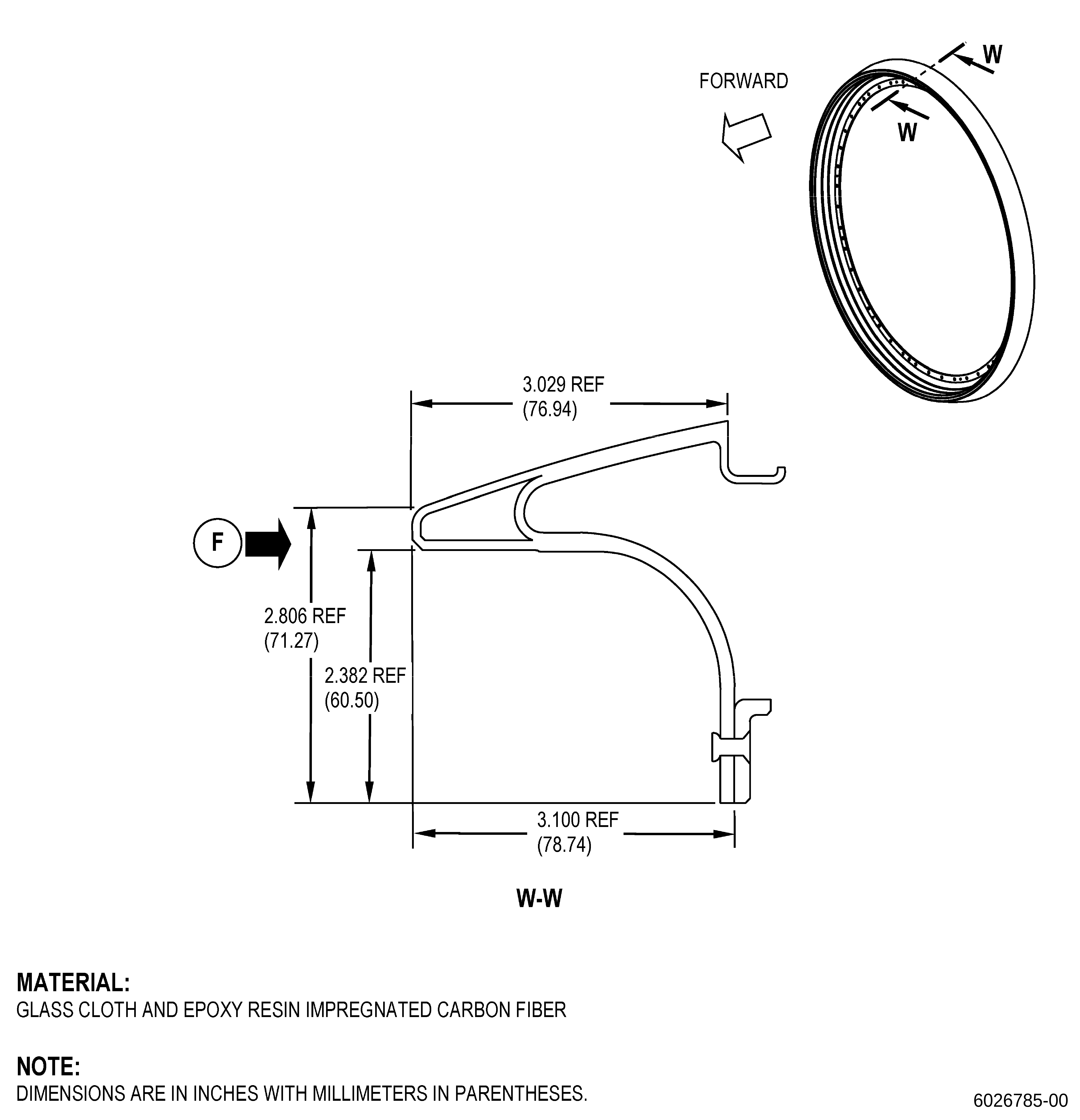
| A. | This procedure gives instructions to repair the flowpath spacer by removing damage and applying polyurethane paste adhesive to the eroded areas of area F. Refer to Figure 901. |
| B. | The following maximum repairable limits apply to this repair: |
| NOTE: |
|
| NOTE: |
|
| (4) | Visual Inspection. |
| (g).A. | Do an inspection of area F of the flowpath spacers (01-060 , 72-22-00) (SIN 830AM). Refer to Figure 818. |
| 1 | Erosion in the glass fiber erosion layer or carbon fiber layer: |
| Maximum repairable limit: |
|
| 2 | Gouges, cuts, or scratches in the glass fiber erosion layer: |
| Maximum repairable limit: |
|
| NOTE: |
|
| (3) | Visual Inspection. |
| (t) | Do an inspection of area F of the flowpath spacers (01-060 , 72-22-00) (SIN 830AM). Refer to Figure 806. |
| 1 | Erosion in the glass fiber erosion layer or carbon fiber layer: |
| Maximum repairable limit: |
|
| 2 | Gouges, cuts, or scratches in the glass fiber erosion layer: |
| Maximum repairable limit: |
|
| NOTE: |
|
| (4) | Visual Inspection. |
| (g) | Do an inspection of area F of the flowpath spacers (01-060 , 72-22-00) (SIN 830AM). Refer to Figure 802. |
| 4 | Erosion in the glass fiber erosion layer or carbon fiber layer: |
| Maximum repairable limit: |
|
| 5 | Gouges, cuts, or scratches in the glass fiber erosion layer: |
| Maximum repairable limit: |
|
| C. | The subsequent table gives a list of the part numbers that are applicable to this procedure. All part numbers are applicable to all paragraphs unless specified differently. |
|
|||||||||||||||||||||||
| D. | Proprietary/Complex Process Statement. |
| (1) | None. |
| 2 . | Tools, Equipment, and Materials. |
| NOTE: |
|
| A. | Tools and Equipment. |
| (1) | Special Tools. None. |
| (2) | Standard Tools and Equipment. |
| (3) | Locally Manufactured Tools. |
|
| B. | Consumable Materials. |
|
| C. | Referenced Procedures. |
|
| D. | Expendable Parts. None. |
| E. | SPD Information. |
| (1) | Spares Supplied. None. |
| (2) | Protected Spares. None. |
| (3) | Locally Manufactured Spares. None. |
| F. | Special Solutions. None. |
| G. | Test Specimens. None. |
| 3 . | Dimensional Information. |
| Subtask 72-22-43-220-048 |
| A. | Refer to Figure 901 for specified dimensions and locations. |
| NOTE: |
|
| NOTE: |
|
| 4 . | Setup Information. |
| None. |
| 5 . | Procedure. |
| Subtask 72-22-43-350-005 |
| NOTE: |
|
| A. | If you do this repair with the flowpath spacer installed on the fan booster module, do as follows: |
| (1) | Remove the fan blade and adjacent fan platforms to get access to the repair area. |
| Subtask 72-22-43-350-006 |
| B. | Apply masking to the areas of the flowpath spacer that you will not repair. Refer to TASK 70-46-01-350-030 (MASKING AND CLEANING OF EPOXY AND POLYESTER MATRIX THERMOSETTING COMPOSITE MATERIALS), Figure 901, and as follows: |
| (1) | Use Composite Masking Method 3. |
| (2) | Apply masking to all the hardware adjacent to the flowpath spacer to give them protection from sanding unwanted material, spills, and drips. |
| (3) | Make sure that you give protection to the fan booster inlet, fan booster spool, and fan disk. |
| Subtask 72-22-43-220-049 |
| C. | Do an inspection of the flowpath spacer. Refer to Figure 901 and as follows: |
| (1) | If the damage extends more than the limits specified in Figure 901, then you cannot repair the flowpath spacer with this procedure. |
| Subtask 72-22-43-220-050 |
| (2) | Do an inspection of the flowpath spacer for polyurethane paste adhesive applied before on each repair area. Refer to TASK 72-22-43-200-801 (72-22-43, INSPECTION 001), Figure 901, and as follows: |
| NOTE: |
|
| NOTE: |
|
| (a) | If polyurethane paste adhesive was applied before, remove the polyurethane paste adhesive in the repair area as follows: |
| 1 | Apply masking to the flowpath spacer that will not repair. Refer to TASK 70-46-01-350-030 (MASKING AND CLEANING OF EPOXY AND POLYESTER MATRIX THERMOSETTING COMPOSITE MATERIALS) and as follows: |
| a | Use Composite Masking Method 3. |
| WARNING: |
|
| CAUTION: |
|
| 2 | Use a clean C10-182 cloth moist with C04-003 acetone to make the polyurethane paste adhesive soft. |
| WARNING: |
|
| 3 | Use C10-141 120-180 grit abrasive paper to sand the polyurethane paste adhesive. |
| 4 | Do not remove the carbon fiber without damage. |
| 5 | Do paragraph 5.C.(2)(a) again until you fully remove the polyurethane paste adhesive applied before. |
| NOTE: |
|
| Subtask 72-22-43-220-051 |
| (3) | Do an inspection of the flowpath spacer to identify repair areas with missing or eroded paint, primer, fiberglass, or carbon fiber damage. Refer to Figure 901 and as follows: |
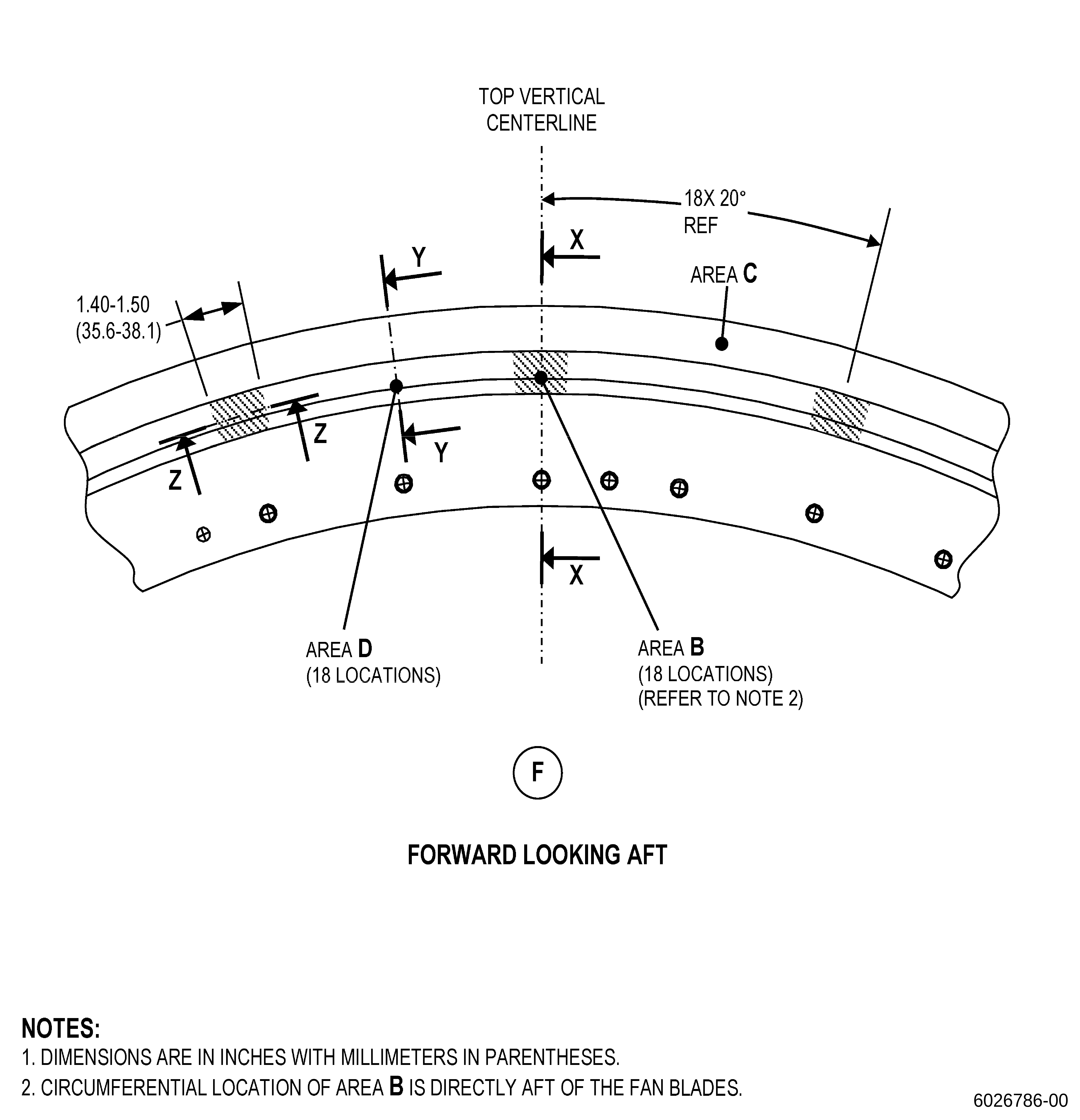
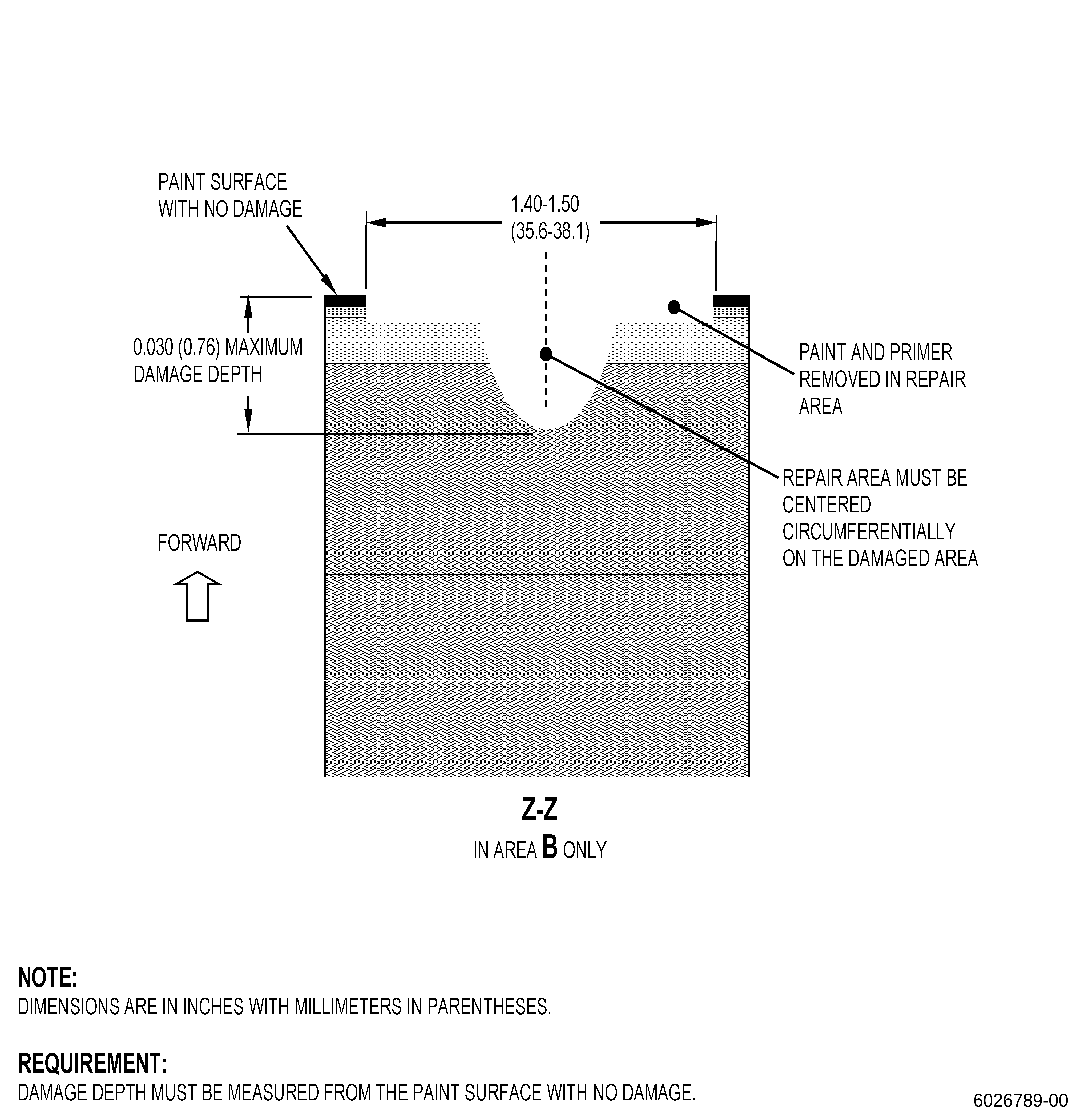
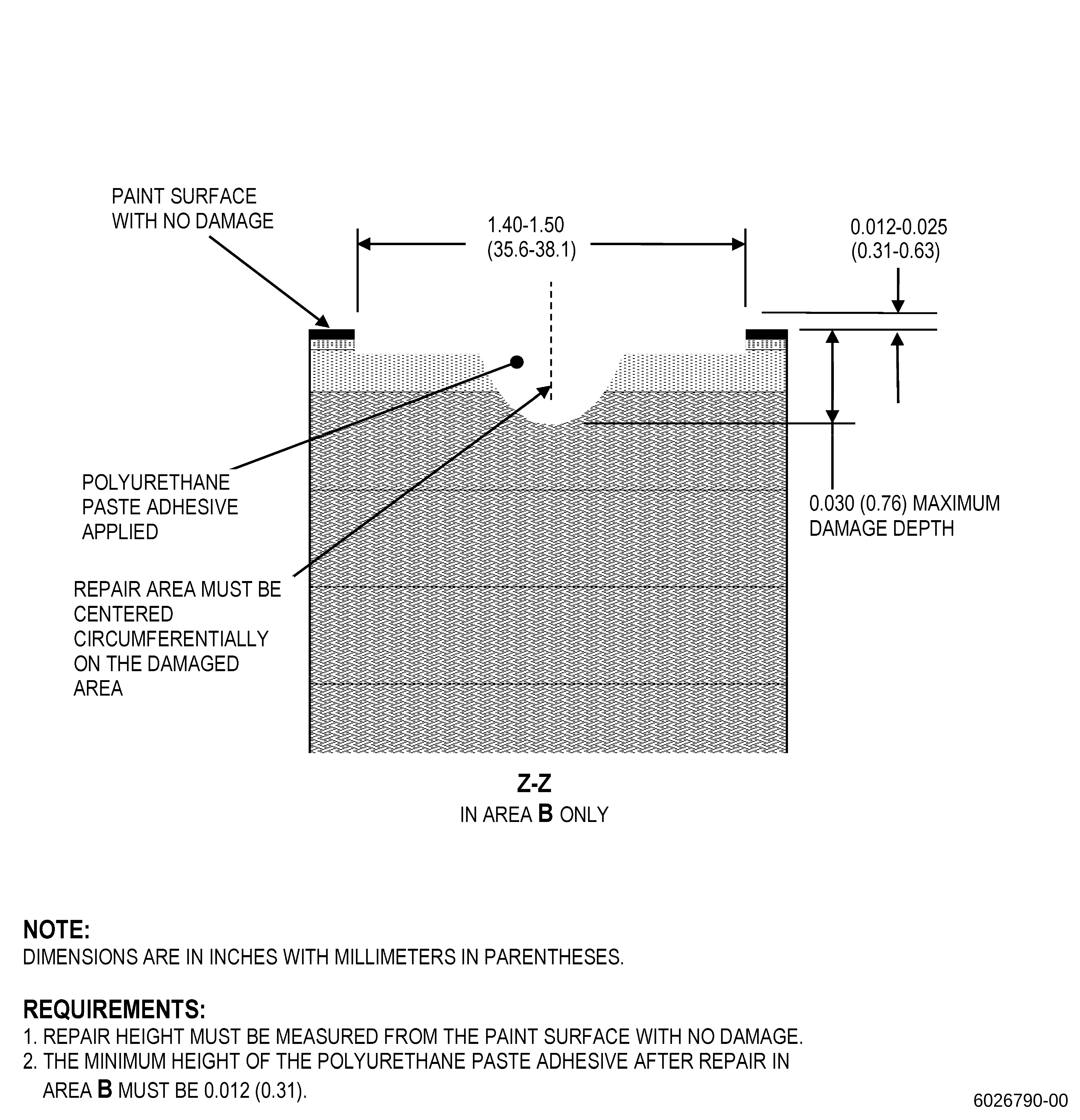
| (a) | Eroded carbon fiber in area B must not be damaged more than 0.030 inch (0.76 mm) in depth, below the painted surface of the flowpath spacer. |
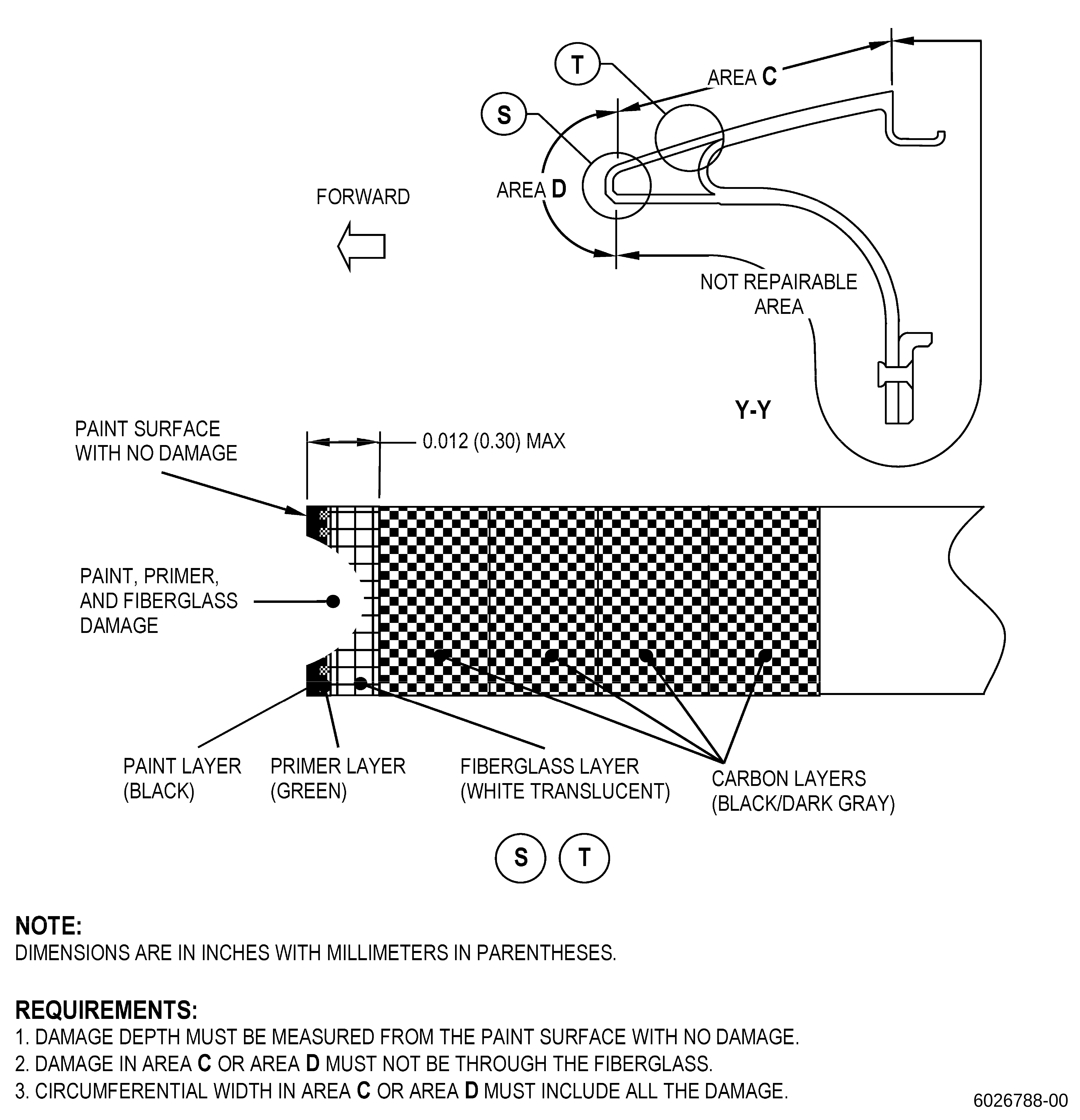
| (b) | Erosion damage in area C and area D must not extend through the fiberglass layer. |
| (c) | Damage more than the limits is not repairable with this procedure. |
| Subtask 72-22-43-350-007 |
| D. | Prepare the flowpath spacer repair areas as follows: |
| WARNING: |
|
| CAUTION: |
|
| (1) | Use C10-141 120-180 grit abrasive paper to lightly sand the flowpath spacer repair area as follows: |
| (a) | Remove the paint and the primer from the repair area, but do not remove erosion damage. |
| (b) | Remove loose fiberglass and carbon fibers. |
| (c) | Do not remove the fiberglass or carbon fibers without damage. Only make rough the exposed carbon fiber. |
| (d) | Do not increase the depth of the repair area. |
| (e) | The repair area in area B must have a width of 1.40-1.50 inches (35.6-38.1 mm) and must be centered circumferentially on the erosion area. Refer to Figure 902. |
| (f) | Do not increase the size of the repair area in area B, area C, or area D. |
| (g) | Use a clean C10-182 cloth moist with water to clean the flowpath spacer surface to keep it cool. You must not see steam on the surface that you clean. |
| Subtask 72-22-43-220-052 |
| E. | Do an inspection of the exposed carbon fiber on the flowpath spacer for damage after sanding. Refer to Figure 901, Figure 902, Figure 905, and as follows: |
| (1) | Carbon fiber damage in area B must not be more than 0.030 inch (0.76 mm) in depth, below the painted surface of the flowpath spacer repair area. |
| (2) | Exposed carbon fiber in area C and area D is not permitted. |
| Subtask 72-22-43-110-011 |
| F. | Clean the flowpath spacer repair area. Refer to TASK 70-46-01-350-030 (MASKING AND CLEANING OF EPOXY AND POLYESTER MATRIX THERMOSETTING COMPOSITE MATERIALS) and as follows: |
| NOTE: |
|
| (1) | Use C10-139 gloves to touch the flowpath spacer. |
| WARNING: |
|
| CAUTION: |
|
| (2) | Use Composite Cleaning Method 4 or Composite Cleaning Method 5, and as follows: |
| NOTE: |
|
| Subtask 72-22-43-160-006 |
| (a) | Alternative Procedure Available. Use C04-035 isopropyl alcohol. |
| Subtask 72-22-43-160-007 |
| (a).A. | Alternative Procedure. Use C04-003 acetone and as follows: |
| 1 | Apply masking to the repair area as follows: |
| a | Use Composite Masking Method 5. |
| 2 | Use small quantities of C04-003 acetone to prevent damage of the adjacent areas. |
| 3 | Do not let the C04-003 acetone stay on the repair area surface more than 10 seconds. |
| Subtask 72-22-43-220-053 |
| 4 | Do an inspection of the adjacent repair area as follows: |
| a | Use C10-139 gloves to touch the flowpath spacer. |
| b | Remove the masking from the repair area. |
| c | Do an inspection of the repair areas with polyurethane paste adhesive applied before for damaged or soft areas as follows: |
| (1) | Do Subtask 72-22-43-220-050 (paragraph 5.C.(2)(a)) again to remove the damaged or soft areas of polyurethane paste adhesive. |
| Subtask 72-22-43-350-008 |
| G. | Apply masking around the flowpath spacer repair area. Refer to TASK 70-46-01-350-030 (MASKING AND CLEANING OF EPOXY AND POLYESTER MATRIX THERMOSETTING COMPOSITE MATERIALS) and as follows: |
| (1) | Use C10-139 gloves to touch the flowpath spacer. |
| (2) | Remove all the masking that you applied before in the repair area. |
| (3) | Use Composite Masking Method 5. |
| Subtask 72-22-43-160-008 |
| H. | Clean the flowpath spacer repair area. Refer to TASK 70-46-01-350-030 (MASKING AND CLEANING OF EPOXY AND POLYESTER MATRIX THERMOSETTING COMPOSITE MATERIALS) and as follows: |
| NOTE: |
|
| (1) | Use C10-139 gloves to touch the flowpath spacer. |
| WARNING: |
|
| CAUTION: |
|
| (2) | Use Composite Cleaning Method 4 or Composite Cleaning Method 5 and as follows: |
| NOTE: |
|
| Subtask 72-22-43-160-009 |
| (a) | Alternative Procedure Available. Use C04-035 isopropyl alcohol. |
| Subtask 72-22-43-160-010 |
| CAUTION: |
|
| (a).A. | Alternative procedure. Use C04-003 acetone and as follows: |
| 1 | Use a clean syringe or a clean eyedropper. |
| 2 | Flush the syringe or eyedropper with C04-003 acetone before you use it. |
| 3 | Use the syringe or eyedropper to apply small quantities of C04-003 acetone to prevent damage of the adjacent areas. |
| 4 | Do not let the C04-003 acetone stay on the repair area more than 10 seconds. |
| Subtask 72-22-43-350-009 |
| I. | Do a water break test to the flowpath spacer repair area. Refer to TASK 70-46-01-350-030 (MASKING AND CLEANING OF EPOXY AND POLYESTER MATRIX THERMOSETTING COMPOSITE MATERIALS) and as follows: |
| (1) | Dry the flowpath spacer in air for 30 minutes minimum after the test. |
| Subtask 72-22-43-350-010 |
| WARNING: |
|
| J. | Alternative Procedure Available. Prepare the C06-067 polyurethane paste adhesive as follows: |
| (1) | Put the C06-067 polyurethane paste adhesive cartridge into the applicator. |
| (2) | Remove the cap from the end of the cartridge and attach the mixing nozzle to the end of the cartridge. |
| (3) | Start to squeeze the trigger on the applicator to let the C06-067 polyurethane paste adhesive flow into the mixing nozzle. |
| (4) | Continue to squeeze the trigger on the applicator until the C06-067 polyurethane paste adhesive starts to come out of the end of the mixing nozzle. |
| (5) | Squeeze-out a minimum of filled diameter of 1.0 inch (26 mm) by 0.05 inch (1.3 mm) in thickness of C06-067 polyurethane paste adhesive from the applicator and discard it before you use the C06-067 polyurethane paste adhesive on the flowpath spacer repair area. |
| (6) | After you complete the repair, remove and discard the mixing nozzle and replace the cap on the cartridge. |
| NOTE: |
|
| Subtask 72-22-43-350-011 |
| WARNING: |
|
| J.A. | Alternative Procedure. Prepare the C06-067 polyurethane paste adhesive as follows: |
| (1) | Put C06-067 polyurethane paste adhesive the cartridge into the applicator. |
| (2) | Remove the cap from the end of the cartridge. |
| (3) | Start to squeeze the trigger on the applicator to let the C06-067 polyurethane paste adhesive flow onto the clean surface/container. |
| (4) | Mix the C06-067 polyurethane paste adhesive with spatula until is uniform. |
| (5) | Make sure that the C06-067 polyurethane paste adhesive mix is uniform before you apply it to the part. |
| (6) | After you complete the repair, replace the cap on the cartridge. |
| Subtask 72-22-43-350-012 |
| WARNING: |
|
| K. | Apply the C06-067 polyurethane paste adhesive to the flowpath spacer repair area. Refer to Figure 903 and as follows: |
| (1) | Use C10-139 gloves to touch the flowpath spacer. |
| (2) | If you do the repair in area B, make sure that the height of the C06-067 polyurethane paste adhesive is 0.012-0.025 inch (0.31-0.63 mm) above the paint surface without damage and as follows: |
| (a) | If necessary, apply C10-040 Teflon tape in the adjacent repair area to agree with the minimum thickness requirements. |
| (3) | If you do the repair in area C, make sure that the height of the C06-067 polyurethane paste adhesive is 0.00-0.015 inch (0.00-0.38 mm) above the paint surface without damage and as follows: |
| NOTE: |
|
| (a) | If necessary, apply C10-040 Teflon tape in the adjacent repair area to agree with the minimum thickness requirements. |
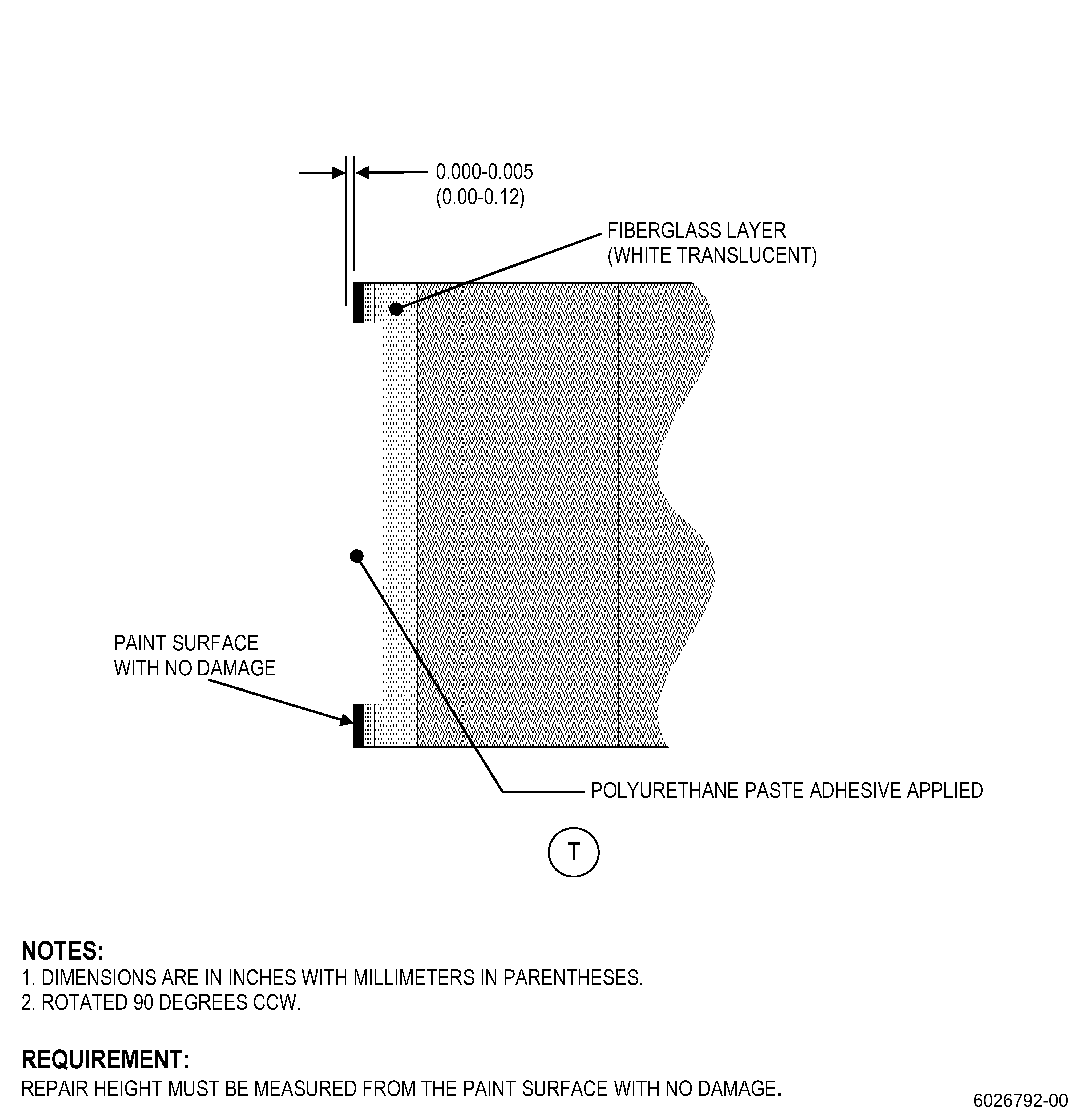
| (4) | If you do the repair in area D, make sure that the height of the C06-067 polyurethane paste adhesive is 0.00-0.005 inch (0.00-0.12 mm) above the paint surface without damage and as follows: |
| NOTE: |
|
| (a) | If necessary, apply C10-040 Teflon tape in the adjacent repair area to agree with the minimum thickness requirements. |
| Subtask 72-22-43-350-013 |
| NOTE: |
|
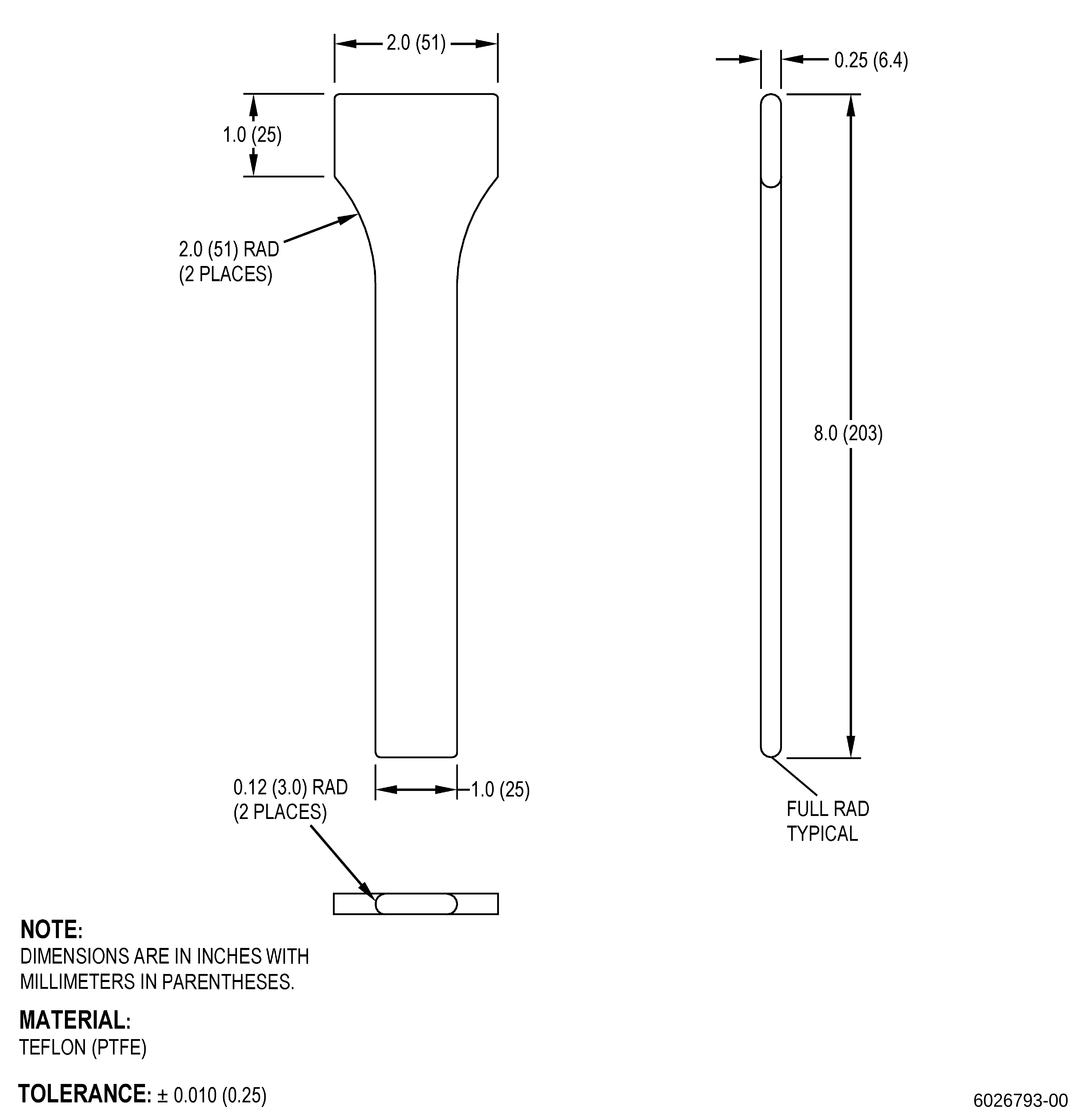
| (5) | Alternative Procedure Available. Make a Teflon spatula to apply the C06-067 polyurethane paste adhesive. Refer to Figure 904 and as follows: |
| (a) | Use the Teflon spatula to make the C06-067 polyurethane paste adhesive smooth. |
| Subtask 72-22-43-350-014 |
| (5).A. | Alternative Procedure. Apply a piece of C10-133 release film on top of the C06-067 polyurethane paste adhesive as follows: |
| (a) | Use a roller on the C10-133 release film to make the C06-067 polyurethane paste adhesive application smooth. |
| (b) | It is not necessary for the C10-133 release film to touch the C06-067 polyurethane paste adhesive. |
| (c) | It is recommended to use the C10-133 release film to get a satisfactory cure if the flowpath spacer is not cured in a low moisture environment (relative humidity is less than 40 percent). |
| (d) | To get a better surface finish, it is recommended that the C10-133 release film does not touch the surface of the C06-067 polyurethane paste adhesive. |
| Subtask 72-22-43-350-015 |
| (6) | Remove unwanted polyurethane paste adhesive with a C10-182 cloth. |
| Subtask 72-22-43-350-016 |
| (7) | Optional Procedure. Remove the masking from the repair area. |
| NOTE: |
|
| Subtask 72-22-43-350-017 |
| WARNING: |
|
| WARNING: |
|
| L. | Alternative Procedure Available. Cure the C06-067 polyurethane paste adhesive at room temperature, at a temperature range of 65 to 85°F (19 to 29°C) for 24 hours. |
| Subtask 72-22-43-350-018 |
| WARNING: |
|
| WARNING: |
|
| L.A. | Alternative Procedure. Cure the C06-067 polyurethane paste adhesive. Refer to SAE ARP 5144, Heat Application for Thermosetting Resin Curing, and as follows: |
| (1) | Use a heating device if the relative humidity is more than 40 percent. |
| NOTE: |
|
| (2) | Attach a minimum of one thermocouple at a maximum of 0.50 inch (12.7 mm) from each repair area. |
| (3) | If you repair more than three areas on the flowpath spacer and you use an oven to increase the temperature of the part, then only three thermocouples are necessary. |
| Subtask 72-22-43-350-019 |
| (4) | Alternative Procedure Available. Keep the repair area at a temperature range of 130 to 170°F (55 to 76°C) for 120-150 minutes. |
| (a) | Increase the temperature at a maximum rate of 6°F (3°C) for each minute. |
| Subtask 72-22-43-350-020 |
| (4).A. | Alternative Procedure. Keep the repair area at a temperature range of 170 to 190°F (77 to 87°C) for 60-90 minutes. |
| (a) | Increase the temperature at a maximum rate of 6°F (3°C) for each minute. |
| Subtask 72-22-43-350-021 |
| (5) | The flowpath spacer temperature must not be more than 190°F (87°C). |
| Subtask 72-22-43-350-022 |
| M. | If necessary, remove the release film and masking from the flowpath spacer. |
| Subtask 72-22-43-350-023 |
| WARNING: |
|
| N. | If necessary, sand the flowpath spacer repair area as follows: |
| (1) | Use C10-141 120-180 grit abrasive paper to sand C06-067 polyurethane paste adhesive to a smooth transition. Refer to Figure 903 and as follows: |
| (a) | After you removed the release film, sanding is not necessary if the surface of the C06-067 polyurethane paste adhesive has the necessary transition. |
| (b) | The height of the repaired area measured from the paint surface with no damage must agree with the limits in Figure 903. |
| (c) | If necessary, sand the surface of the C06-067 polyurethane paste adhesive to have a matte finish. |
| Subtask 72-22-43-220-054 |
| O. | Do a visual inspection of the flowpath spacer repair area as follows: |
| (1) | Do an inspection for bubbles, blisters, and contamination. If you find bubbles, blisters, or contamination more than 0.005 inch (0.12 mm) in depth, do the repair again. |
| (2) | Make sure that the repair area of the exposed fiberglass and carbon fiber in the flowpath spacer has a full cover of C06-067 polyurethane paste adhesive. If the exposed carbon fiber in the flowpath spacer repair area has missing C06-067 polyurethane paste adhesive, do the repair again. |
| (3) | Do an inspection of the C06-067 polyurethane paste adhesive make sure that it is cured as follows: |
| (a) | Do an inspection of shape memory (surface keeps initial shape) as follows: |
| 1 | Apply force with the Teflon spatula to the cured surface to cause a movement of 0.001-0.003 inch (0.03-0.07 mm). |
| 2 | Remove the Teflon spatula. |
| 3 | Make sure that the surface of the C06-067 polyurethane paste adhesive keeps the initial shape (shape memory). |
| (b) | The cured surface must be dry. |
| (c) | If the C06-067 polyurethane paste adhesive is not cured, remove the non-cured C06-067 polyurethane paste adhesive from the repair area and do the repair again. |