| GENX-1B CLEANING,INSPECTION,AND REPAIR MANUAL | Dated: 01/31/2025 | |
| CIR 72-00-22 , INSPECTION 001 | ||
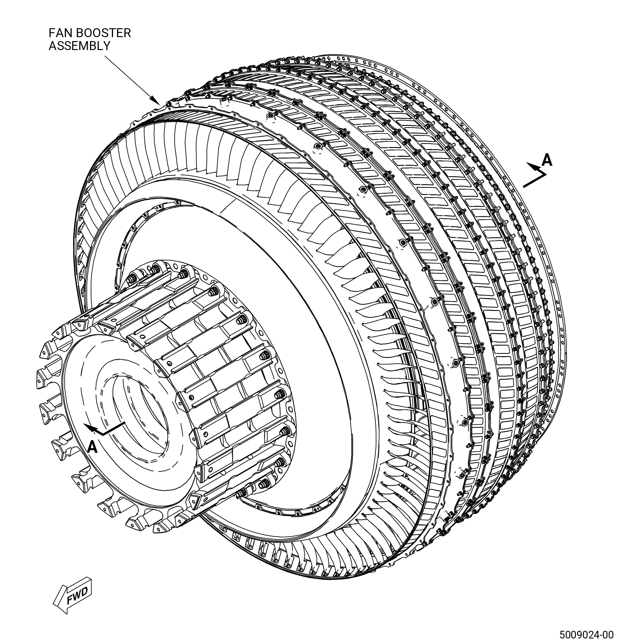
| FAN BOOSTER ASSEMBLY - INSPECTION | ||
| GENX-1B CLEANING,INSPECTION,AND REPAIR MANUAL | Dated: 01/31/2025 | |
| CIR 72-00-22 , INSPECTION 001 | ||
| FAN BOOSTER ASSEMBLY - INSPECTION | ||
| * * * FOR ALL |
| TASK 72-00-22-200-801 |
| 1 . | General. |
| A. | This procedure gives instructions to do an inspection of the fan booster assembly. Refer to Figure 801. |
| • |
|
| • |
|
| The fan booster assembly includes the parts that follows: |
| • |
|
| • |
|
| • |
|
| • |
|
| • |
|
| • |
|
| • |
|
| • |
|
| • |
|
| • |
|
| • |
|
| • |
|
| B. | Any sub-assembly or part removed for access or limited workscope must be inspected in accordance with criteria in this section. If there is no criteria, the sub-assembly or part must receive a general visual inspection (GVI) for continued serviceability. Refer to TASK 72-00-00-200-805 (72-00-00, INSPECTION 001) . If required, the component can be hand-cleaned to do a visual inspection. Refer to TASK 70-21-01-110-001 (CLEANING METHOD 1 - SOLVENT DEGREASING) or TASK 70-21-03-160-001 (CLEANING METHOD 3 - STEAM CLEANING) . GVI can not be done to components identified in TASK 05-21-00-200-801 (05-21-00, LIFE LIMITS 001) that become piece part. These components must have their appropriate mandatory inspections done, unless stated differently in an applicable Service Bulletin. |
| C. | If you find an assembly or part to be unserviceable with this procedure, refer to the applicable section of the engine manual for more disassembly and inspection procedures for the assembly or part. |
| D. | If personnel will fully disassemble the fan booster assembly, this inspection is not necessary. Refer to the applicable section of the engine manual for the inspection procedure for each part. |
| E. | The maintenance instructions in this Manual do not purport to cover all details or variations in equipment, nor do they provide for every possible contingency to be met in connection with installation, operation, maintenance, or GEAE certified repair facilities. The maintenance instructions are intended to be all-inclusive for a complete teardown and overhaul of the component or sub assembly. The individual procedures as written are one sequence based on General Electric experience. Alternate sequences to these maintenance instructions are at the discretion of the operator and/or overhaul shop provided the intent of the maintenance instructions is met. The operator and/or overhaul shop can select specific tasks to partially disassemble and assemble hardware or subassemblies based upon the on demand maintenance requirement of the individual engine work scope provided the final assembly configuration and requirements contained in the manual have been met. |
| F. | If an axisymmetric rotating part with a visible crack through the axial or radial thickness of the part feature is found during the inspection procedure, then the mating Life Limited Part(s) (LLP) can be affected. The mating LLP must be considered not serviceable and not repairable. |
| NOTE: |
|
| NOTE: |
|
| 2 . | Tools, Equipment, and Materials. |
| NOTE: |
|
| A. | Tools and Equipment. |
| (1) | Special Tools. None. |
| (2) | Standard Tools and Equipment. None. |
| (3) | Locally Manufactured Tools. None. |
| B. | Consumable Materials. None. |
| C. | Referenced Procedures. |
| D. | Expendable Parts. None. |
| 3 . | Visual Inspection. |
| Subtask 72-00-22-220-001 |
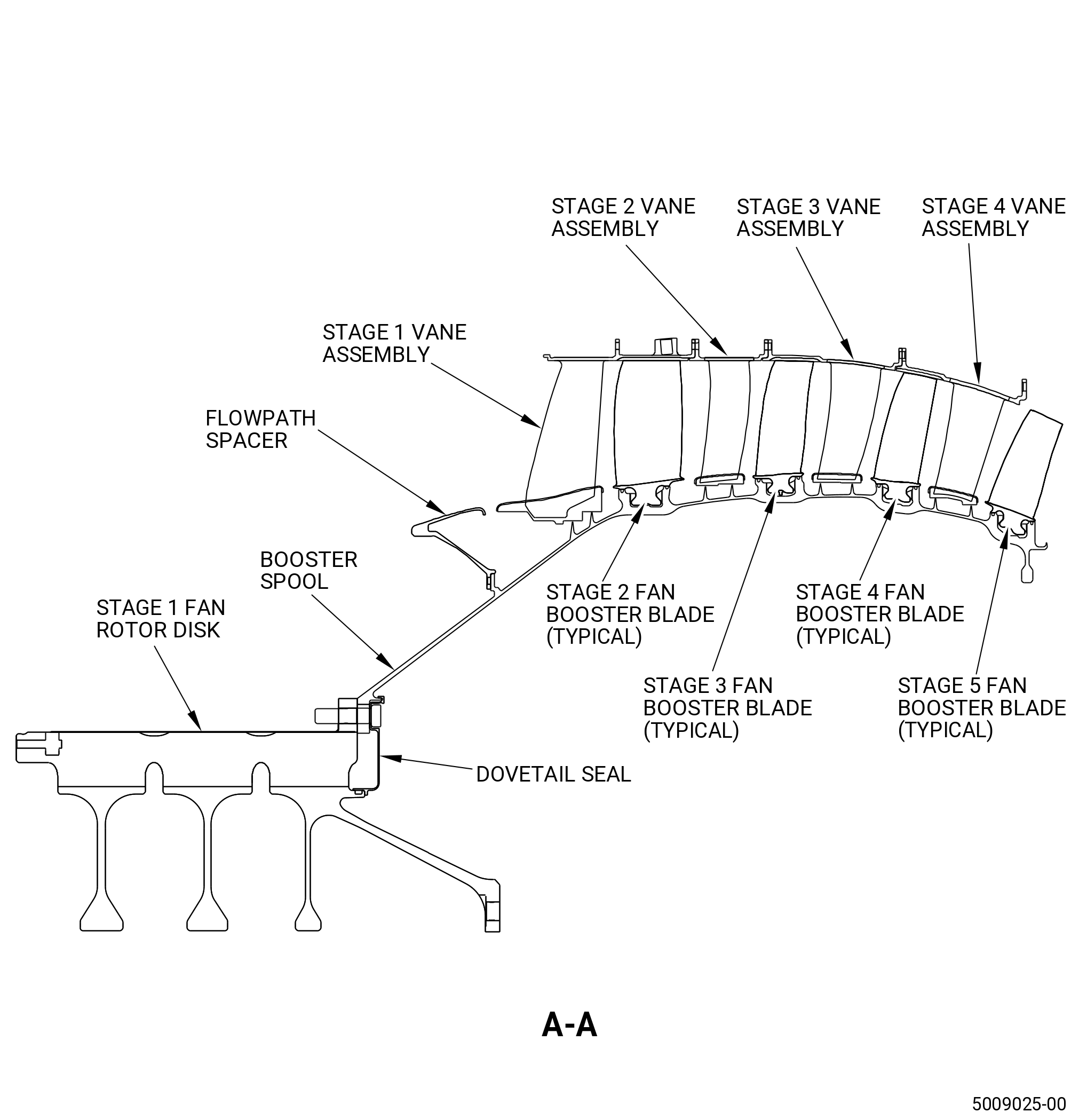
| A. | Do an inspection of all areas of the stage vane assemblies that can be seen as follows. Refer to Figure 802. |
| (1) | Broken vanes: |
| Maximum serviceable limit: |
|
| Repair method: |
|
| Subtask 72-00-22-220-040 |
| (2) | Cracks and tears: |
| Maximum serviceable limit: |
|
| Repair method: |
|
| Subtask 72-00-22-220-002 |
| (3) | Cracks and tears as follows. Refer to Figure 802. |
| Maximum serviceable limit: |
|
| Repair method: |
|
| Subtask 72-00-22-220-041 |
| (4) | Fretting or galling on the flange surfaces that connect: |
| Maximum serviceable limit: |
|
| Repair method: |
|
| Subtask 72-00-22-220-042 |
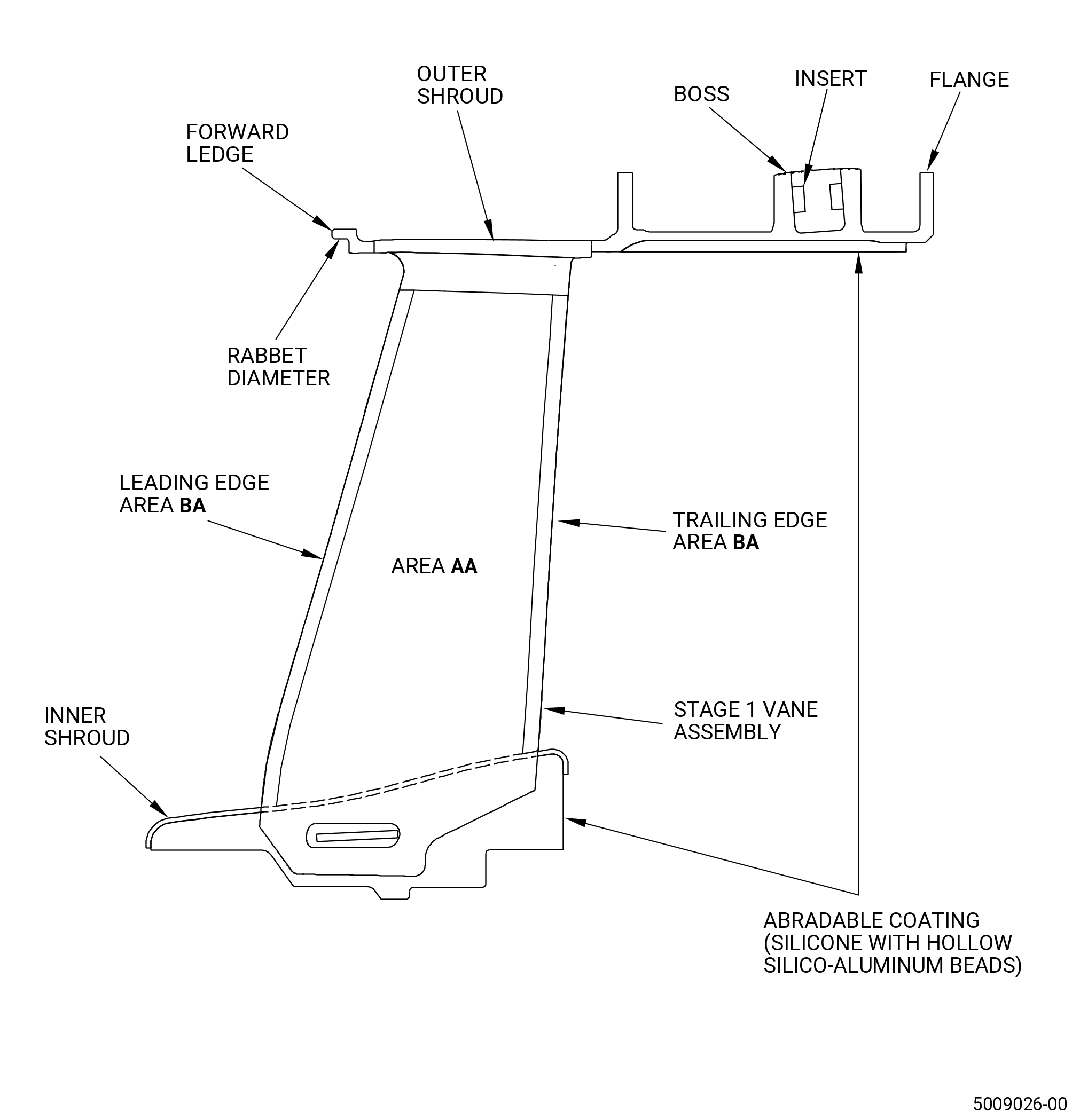
| B. | Do an inspection of the threaded insert inside the boss of the stage 1 vane assembly as follows. Refer to Figure 802. |
| (1) | Missing or loose screw inserts: |
| Maximum serviceable limit: |
|
| Maximum repairable limit: |
|
| Repair method: |
|
| (2) | Damaged threads on screw inserts: |
| Maximum serviceable limit: |
|
| Repair method: |
|
| Subtask 72-00-22-220-003 |
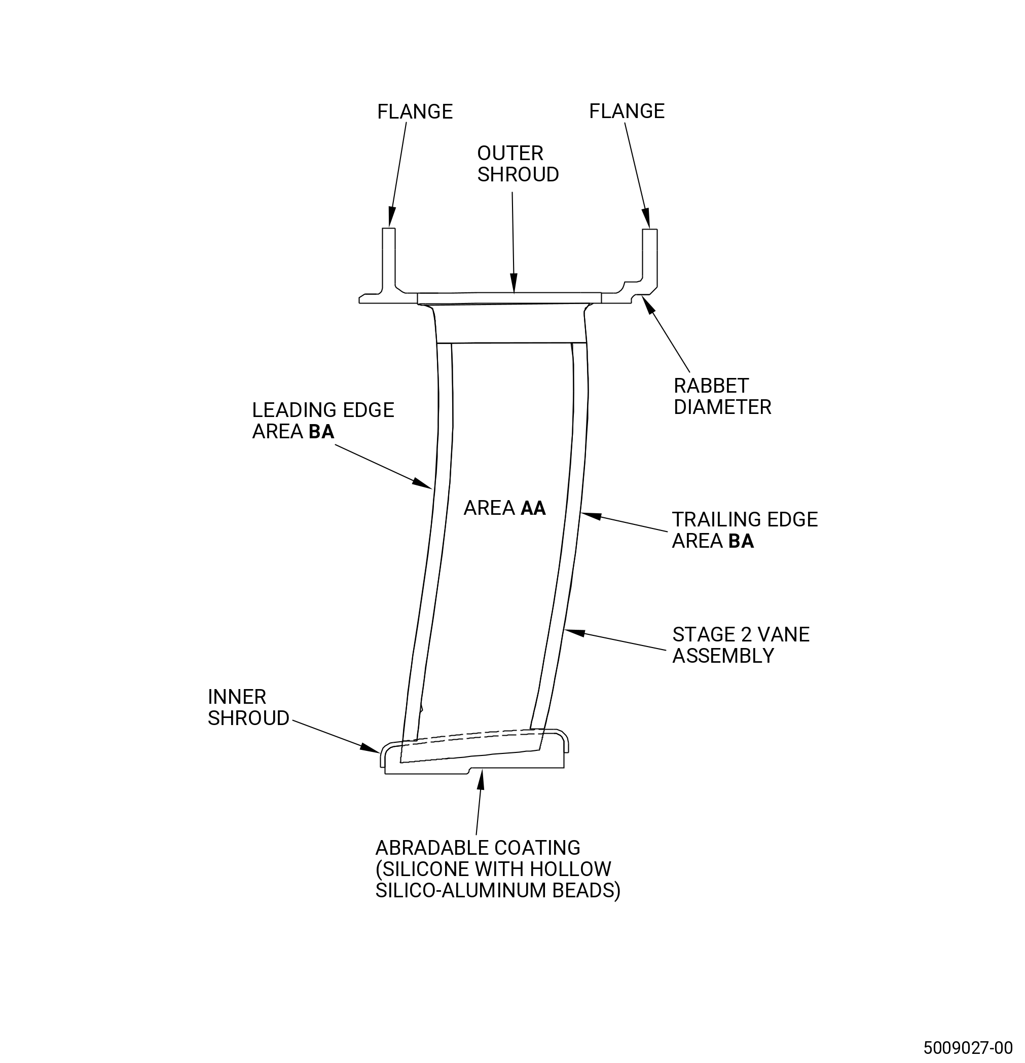
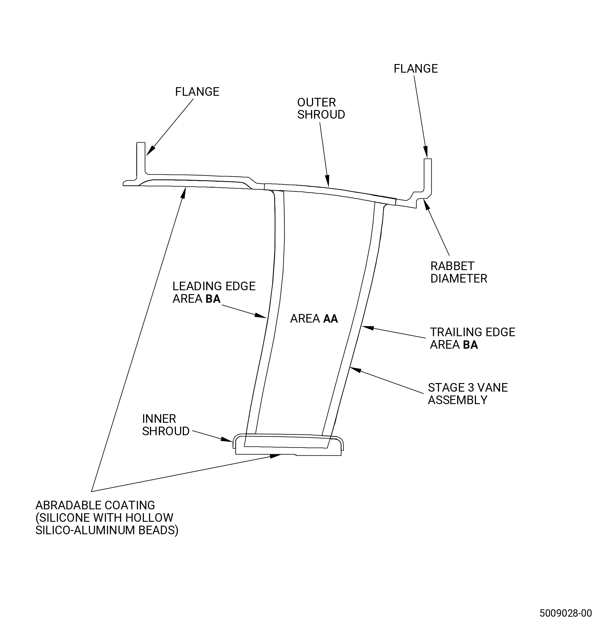
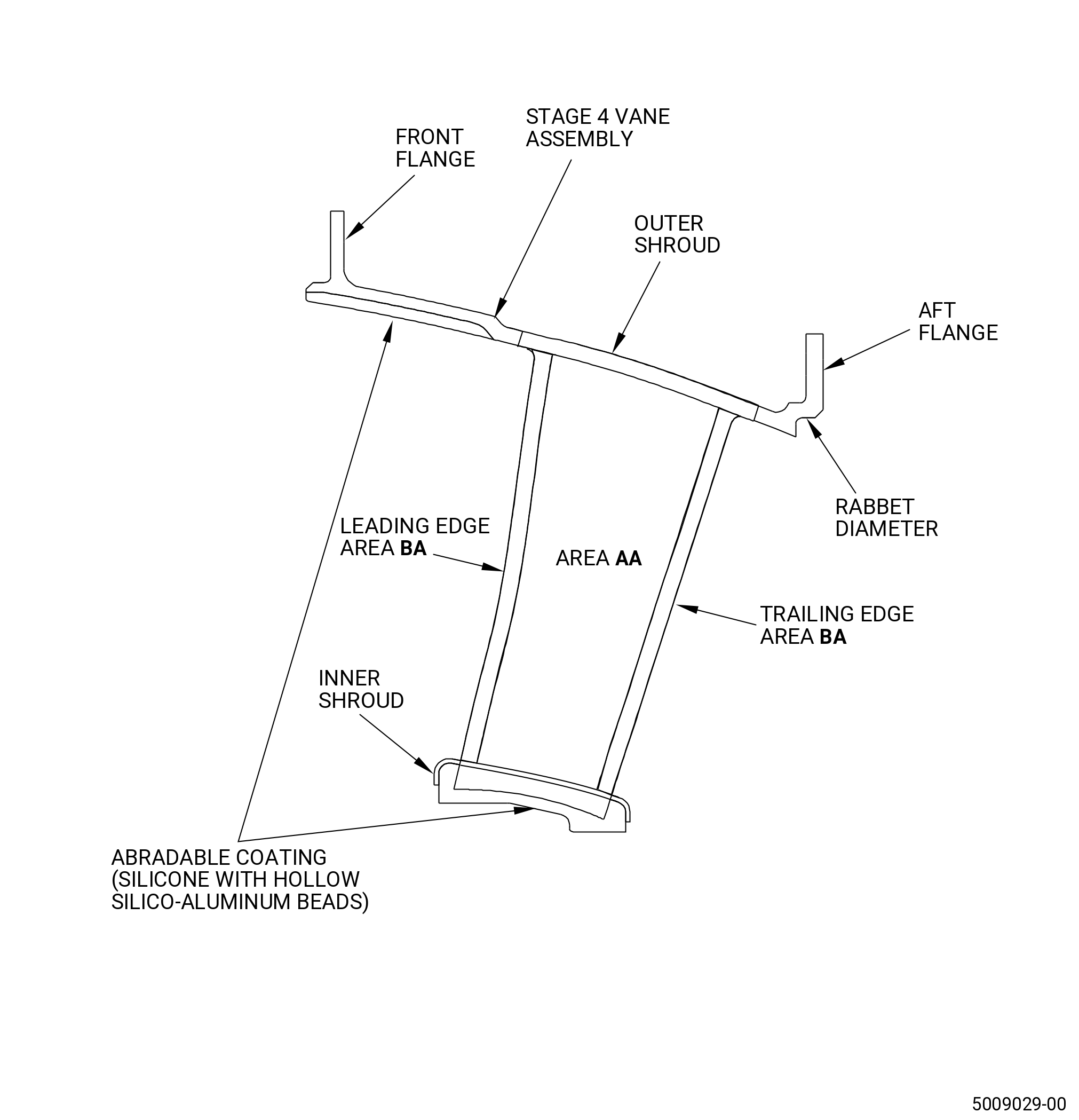
| C. | Do an inspection of area AA on the stages 1-4 vane assemblies that can be seen as follows. Refer to Figure 802. |
| (1) | Cracks and tears: |
| Maximum serviceable limit: |
|
| Repair method: |
|
| Subtask 72-00-22-220-004 |
| (2) | Nicks and dents: |
| Maximum serviceable limit: |
|
| Repair method: |
|
| Subtask 72-00-22-220-005 |
| (3) | Disengaged inner shroud: |
| Maximum serviceable limit: |
|
| Repair method: |
|
| Subtask 72-00-22-220-006 |
| D. | Do an inspection of area BA on the stages 1-4 vane assemblies that can be seen as follows. Refer to Figure 802. |
| (1) | Cracks and tears: |
| Maximum serviceable limit: |
|
| Repair method: |
|
| Subtask 72-00-22-220-007 |
| (2) | Nicks and dents: |
| Maximum serviceable limit: |
|
| Repair method: |
|
| Subtask 72-00-22-220-008 |
| (3) | Distortion of the leading or trailing edge: |
| Maximum serviceable limit: |
|
| Repair method: |
|
| Subtask 72-00-22-220-009 |
| E. | Do an inspection of the inner and outer shrouds of the stages 1-4 vane assemblies that can be seen as follows. Refer to Figure 802. |
| (1) | Cracks and tears: |
| Maximum serviceable limit: |
|
| Repair method: |
|
| Subtask 72-00-22-220-010 |
| (2) | Galling on the rabbet diameter: |
| Maximum serviceable limit: |
|
| Repair method: |
|
| Subtask 72-00-22-220-011 |
| F. | Do an inspection of the abradable material on the stages 1, 3, and 4 vane assemblies that can be seen as follows. Refer to Figure 802. |
| (1) | Erosion of the abradable material on the outer shroud that goes to the parent material: |
| Maximum serviceable limit: |
|
| Repair method: |
|
| Subtask 72-00-22-220-012 |
| (2) | Flaking of the abradable material on the outer shroud: |
| Maximum serviceable limit: |
|
| Repair method: |
|
| Subtask 72-00-22-220-059 |
| (3) | Pitting, nicks, or dents in the abradable coating: |
| Maximum serviceable limit: |
|
| Repair method: |
|
| Subtask 72-00-22-220-015 |
| G. | Do an inspection of all areas of the booster spool as follows. Refer to Figure 801. |
| (1) | Cracks: |
| Maximum serviceable limit: |
|
| Repair method: |
|
| Subtask 72-00-22-220-016 |
| (2) | Nicks, dents, and scratches: |
| Maximum serviceable limit: |
|
| Maximum repairable limit: |
|
| Repair method: |
|
| Subtask 72-00-22-220-017 |
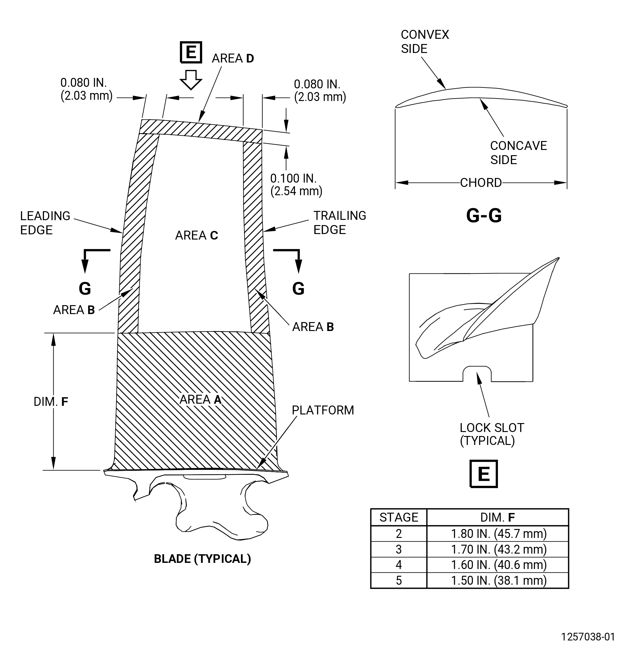
| H. | Do an inspection of the visible areas of each of the stages 2-5 fan booster blades as follows. Refer to Figure 803. |
| (1) | Cracks or tears: |
| Maximum serviceable limit: |
|
| Repair method: |
|
| Subtask 72-00-22-220-018 |
| I. | Do an inspection in area A for each of the stages 2-5 fan booster blades that can be seen as follows. Refer to Figure 803. |
| (1) | Nicks and/or dents on the concave or convex sides of each stage 2 and stage 4 blade chord: |
| Maximum serviceable limit: |
|
| Repair method: |
|
| Subtask 72-00-22-220-019 |
| (2) | Deleted |
| Subtask 72-00-22-220-020 |
| (3) | Nicks and/or dents on the leading edges: |
| Maximum serviceable limit: |
|
| Repair method: |
|
| Subtask 72-00-22-220-022 |
| (4) | Local distortion on the leading or trailing edges: |
| Maximum serviceable limit: |
|
| Repair method: |
|
| Subtask 72-00-22-220-024 |
| (5) | Scratches: |
| Maximum serviceable limit: |
|
| Repair method: |
|
| Subtask 72-00-22-220-025 |
| J. | Do an inspection of area B of each of the stages 2-5 fan booster blades that can be seen as follows. Refer to Figure 803. |
| (1) | Nicks, dents, and scratches: |
| Maximum serviceable limit: |
|
| Repair method: |
|
| Subtask 72-00-22-220-026 |
| (2) | Tears (high metal): |
| Maximum serviceable limit: |
|
| Repair method: |
|
| Subtask 72-00-22-220-027 |
| (3) | Local distortion on the leading and/or trailing edge: |
| Maximum serviceable limit: |
|
| Repair method: |
|
| Subtask 72-00-22-220-028 |
| (4) | Missing blade tip corner: |
| Maximum serviceable limit: |
|
| Repair method: |
|
| Subtask 72-00-22-220-044 |
| (5) | Tip curl: |
| Maximum serviceable limit: |
|
| Repair method: |
|
| Subtask 72-00-22-220-029 |
| K. | Do an inspection of area C of each of the stages 2-5 fan booster blades that can be seen as follows. Refer to Figure 803. |
| (1) | Nicks, dents, and scratches: |
| Maximum serviceable limit: |
|
| Repair method: |
|
| Subtask 72-00-22-220-057 |
| L. | Do an inspection of area D of each of the stages 2-5 fan booster blades that can be seen as follows. Refer to Figure 803. |
| (1) | Nicks, dents, and scratches: |
| Maximum serviceable limit: |
|
| Repair method: |
|
| Subtask 72-00-22-220-058 |
| (2) | Tears (high metal): |
| Maximum serviceable limit: |
|
| Repair method: |
|
| Subtask 72-00-22-220-030 |
| M. | Do an inspection for each platform of the stages 2-5 fan booster blades that can be seen as follows. Refer to Figure 803. |
| (1) | Nicks, dents, and scratches: |
| Maximum serviceable limit: |
|
| Maximum repairable limit: |
|
| Repair method: |
|
| Subtask 72-00-22-220-032 |
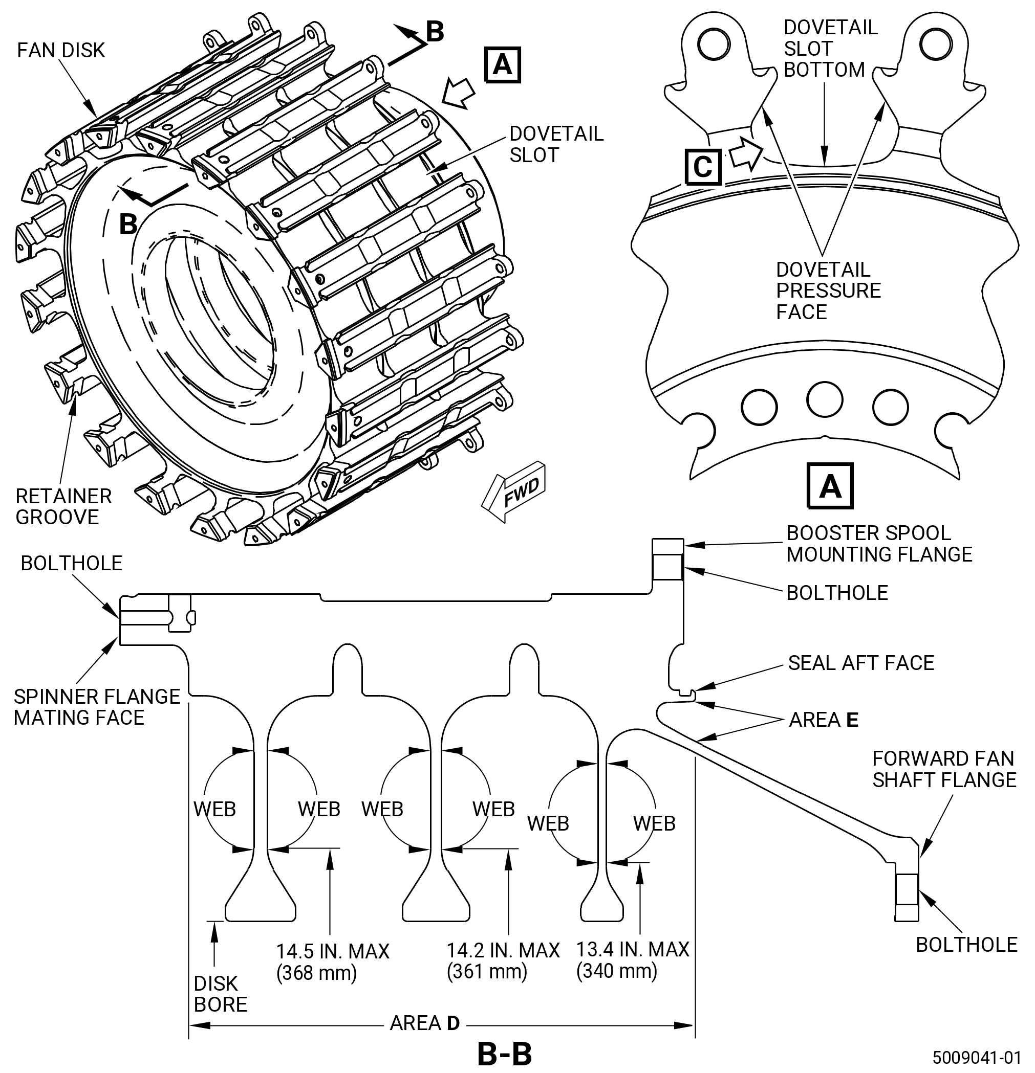
| N. | Do an inspection of all areas of the fan disk as follows. Refer to Figure 804. |
| (1) | Cracks: |
| Maximum serviceable limit: |
|
| Repair method: |
|
| Subtask 72-00-22-220-045 |
| (2) | Discoloration that is a result of a shotpeen procedure (rust color): |
| Maximum serviceable limit: |
|
| Repair method: |
|
| Subtask 72-00-22-220-046 |
| (3) | Nicks, dents, and scratches (this does not include area E in the seal aft face, the retainer grooves, or area D in the webs): |
| Maximum serviceable limit: |
|
| Repair method: |
|
| Subtask 72-00-22-220-047 |
| (4) | Nicks, dents, and scratches in the web areas: |
| Maximum serviceable limit: |
|
| Repair method: |
|
| Subtask 72-00-22-220-048 |
| (5) | Nicks, dents, scratches, and fretting (on the seal aft face only): |
| Maximum serviceable limit: |
|
| Repair method: |
|
| Subtask 72-00-22-220-049 |
| (6) | Nicks, dents, scratches, and fretting (in the retainer grooves only): |
| Maximum serviceable limit: |
|
| Repair method: |
|
| Subtask 72-00-22-220-033 |
| O. | Do an inspection of the boltholes in the spinner flange mating face, the booster spool mounting flange, and the forward fan shaft flange of the fan disk as follows. Refer to Figure 804. |
| (1) | Cracks: |
| Maximum serviceable limit: |
|
| Repair method: |
|
| Subtask 72-00-22-220-034 |
| (2) | Galling and scratches: |
| Maximum serviceable limit: |
|
| Repair method: |
|
| Subtask 72-00-22-220-035 |
| P. | Do an inspection of the dovetail slots of the fan disk as follows. Refer to Figure 804. |
| (1) | Nicks, dents, scratches, and fretting on the dovetail pressure faces: |
| Maximum serviceable limit: |
|
| Repair method: |
|
| Subtask 72-00-22-220-050 |
| (2) | Nicks, dents, scratches, and fretting on the radius below and adjacent to the dovetail pressure faces: |
| Maximum serviceable limit: |
|
| Repair method: |
|
| Subtask 72-00-22-220-051 |
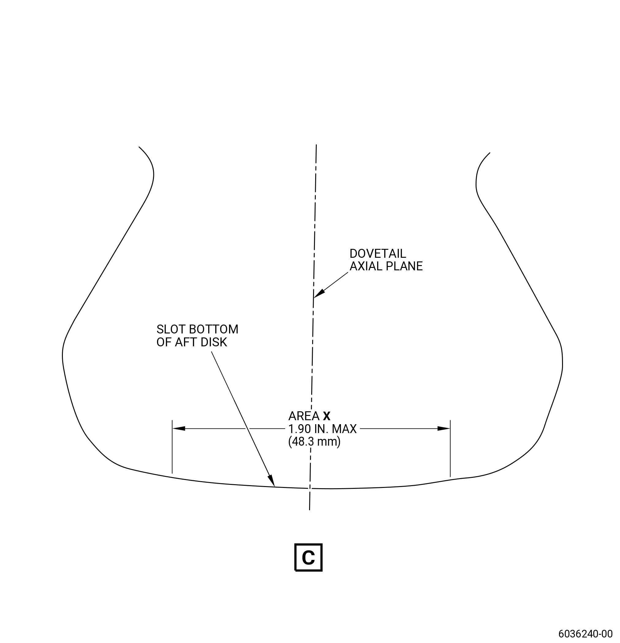
| (3) | Nicks, dents, scratches, and fretting on the bottom of the dovetail slots: |
| Maximum serviceable limit: |
|
| Repair method: |
|
| Subtask 72-00-22-220-067 |
| (4) | Wear/fretting on the bottom of the dovetail slots aft disk because of contact with the dovetail key (20-180 , 72-00-00) (SIN 8300B): |
| Maximum serviceable limit: |
|
| Repair method: |
|
| Subtask 72-00-22-220-060 |
| (5) | Foreign material embedment on the bottom of the dovetail slots from the contact with the fan blade spacer wear strip: |
| NOTE: |
|
| Maximum serviceable limit: |
|
| Repair method: |
|
| Subtask 72-00-22-220-052 |
| (6) | Nicks, dents, and scratches on the corners of the leading and trailing edges of the dovetail: |
| Maximum serviceable limit: |
|
| Repair method: |
|
| Subtask 72-00-22-220-036 |
| Q. | Do an inspection of the mounting flanges and the mating faces of the fan disk as follows. Refer to Figure 804. |
| (1) | Cracks: |
| Maximum serviceable limit: |
|
| Repair method: |
|
| Subtask 72-00-22-220-037 |
| (2) | Nicks, dents, and scratches: |
| Maximum serviceable limit: |
|
| Maximum repairable limit: |
|
| Repair method: |
|
| Subtask 72-00-22-220-038 |
| (3) | Fretting: |
| Maximum serviceable limit: |
|
| Repair method: |
|
| Subtask 72-00-22-220-039 |
| (4) | Rub marks on the booster spool mounting flange from contact with the balance weights: |
| Maximum serviceable limit: |
|
| Repair method: |
|
| Subtask 72-00-22-220-053 |
| R. | Do an inspection of all areas of the flowpath spacer as follows. Refer to Figure 801. |
| (1) | Cracks: |
| Maximum serviceable limit: |
|
| Repair method: |
|
| Subtask 72-00-22-220-054 |
| (2) | Nicks, dents, scratches, and pits: |
| Maximum serviceable limit: |
|
| Maximum repairable limit: |
|
| Repair method: |
|
| Subtask 72-00-22-220-055 |
| S. | Do an inspection of the dovetail seal as follows. Refer to Figure 801. |
| (1) | Cracks: |
| Maximum serviceable limit: |
|
| Repair method: |
|
| Subtask 72-00-22-220-056 |
| (2) | Nicks and scratches: |
| Maximum serviceable limit: |
|
| Repair method: |
|
| Subtask 72-00-22-220-061 |
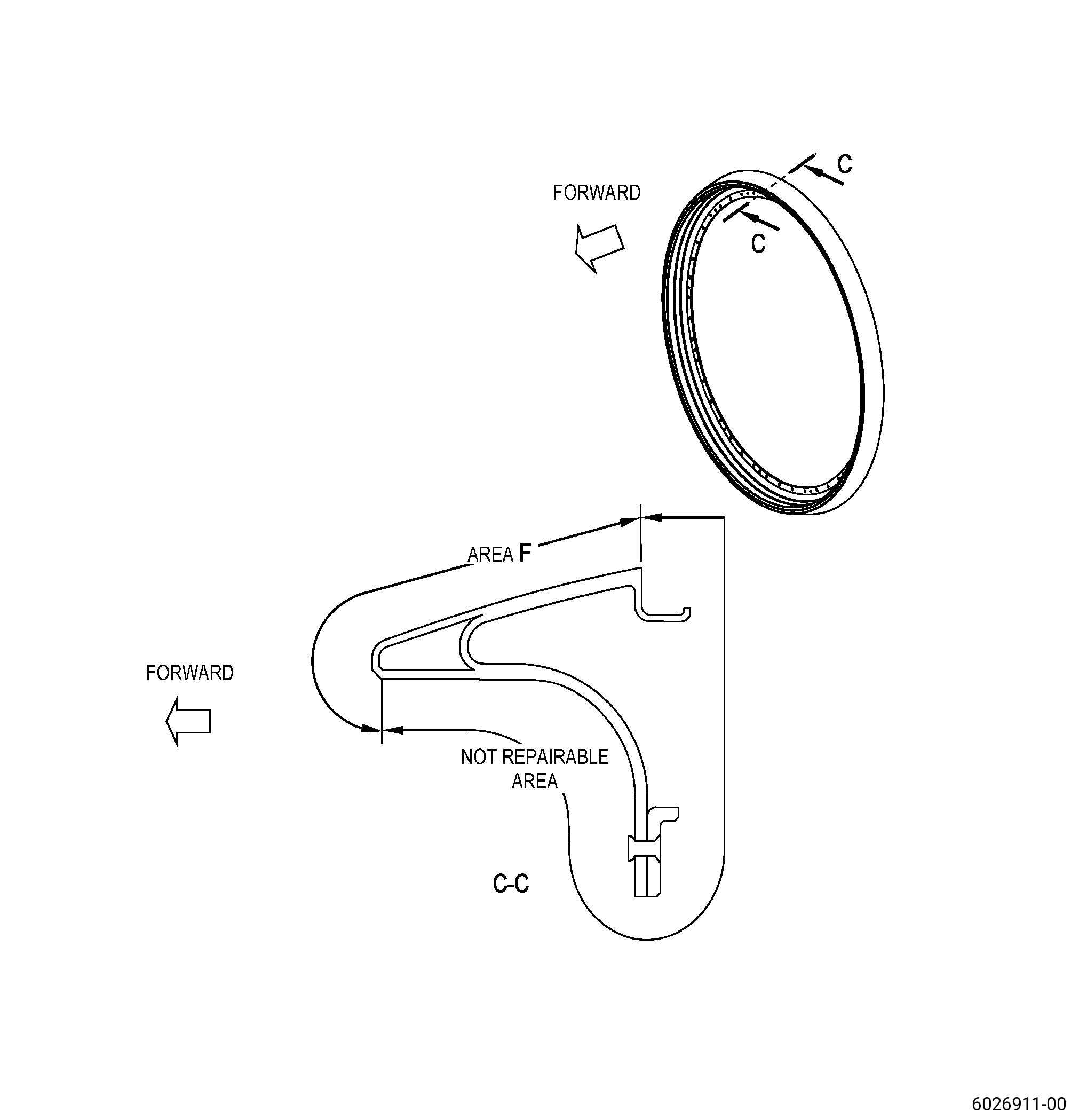
| T. | Do an inspection of area F of the flowpath spacers (01-060 , 72-22-00) (SIN 830AM). Refer to Figure 806. |
| (1) | Erosion in the glass fiber erosion layer or carbon fiber layer: |
| Maximum serviceable limit: |
|
| Repair method: |
|
| Subtask 72-00-22-220-062 |
| (2) | Gouges, cuts, or scratches in the glass fiber erosion layer: |
| Maximum serviceable limit: |
|
| Repair method: |
|