| GENX-1B CLEANING,INSPECTION,AND REPAIR MANUAL | Dated: 01/18/2022 | |
| CIR 72-00-22 , REPAIR 002 | ||
| FAN BOOSTER ASSEMBLY - REPAIR - BLEND REPAIR ON THE DOVETAIL SLOTS BOTTOM OF THE STAGE 1 FAN DISK | ||
| GENX-1B CLEANING,INSPECTION,AND REPAIR MANUAL | Dated: 01/18/2022 | |
| CIR 72-00-22 , REPAIR 002 | ||
| FAN BOOSTER ASSEMBLY - REPAIR - BLEND REPAIR ON THE DOVETAIL SLOTS BOTTOM OF THE STAGE 1 FAN DISK | ||
| * * * FOR ALL |
| TASK 72-00-22-300-801 |
| 1 . | Blend Repair on the Dovetail Slots Bottom of the Stage 1 Fan Disk. |
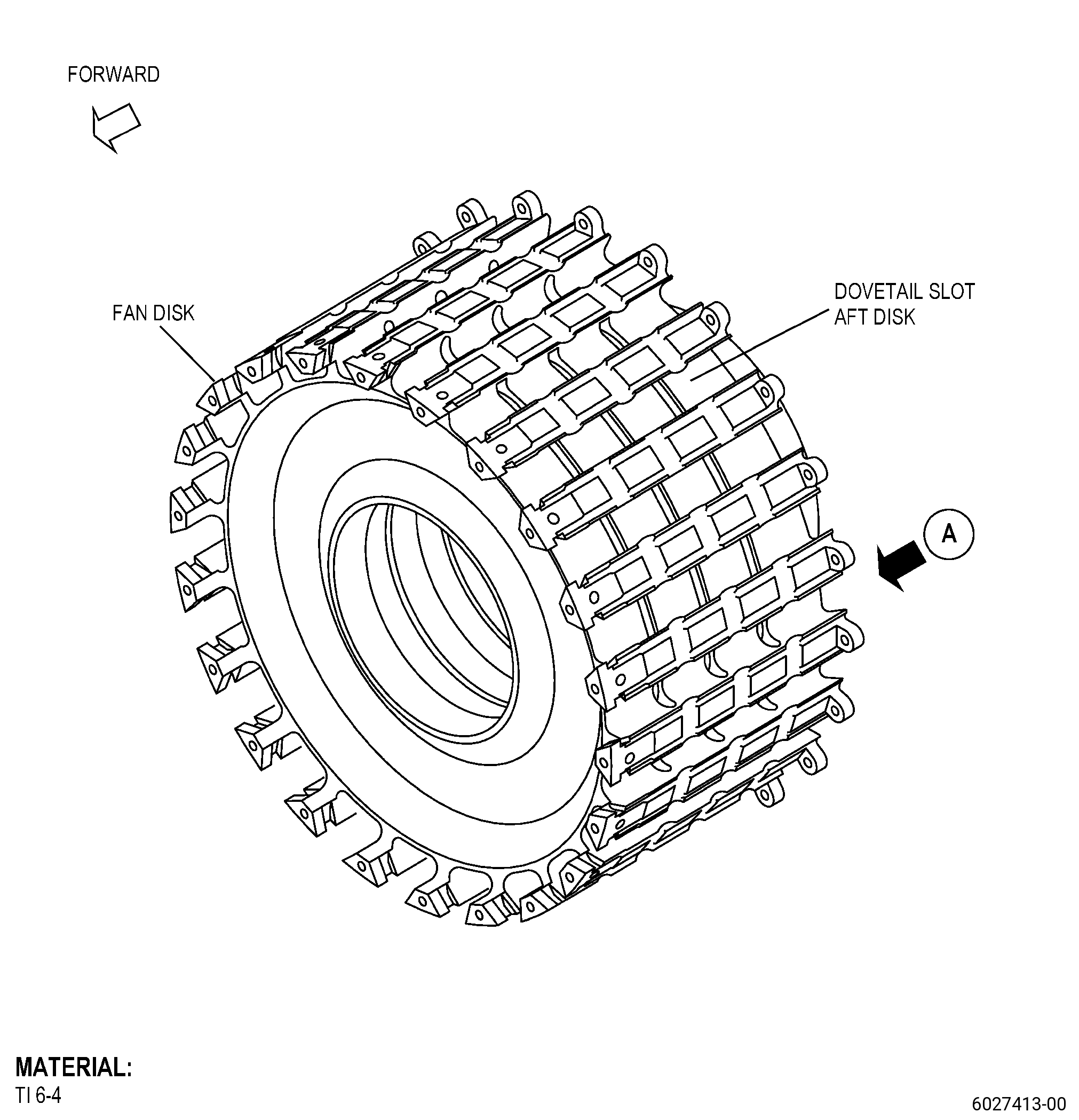
| A. | This procedure gives instructions to repair the fan booster assembly by blending wear/fretting on the dovetail slots bottom of the stage 1 fan disk (fan disk) because of the contact with the dovetail key. Refer to Figure 901. |
| B. | The following maximum repairable limits apply to this repair: |
| NOTE: |
|
| (3) | Visual Inspection. |
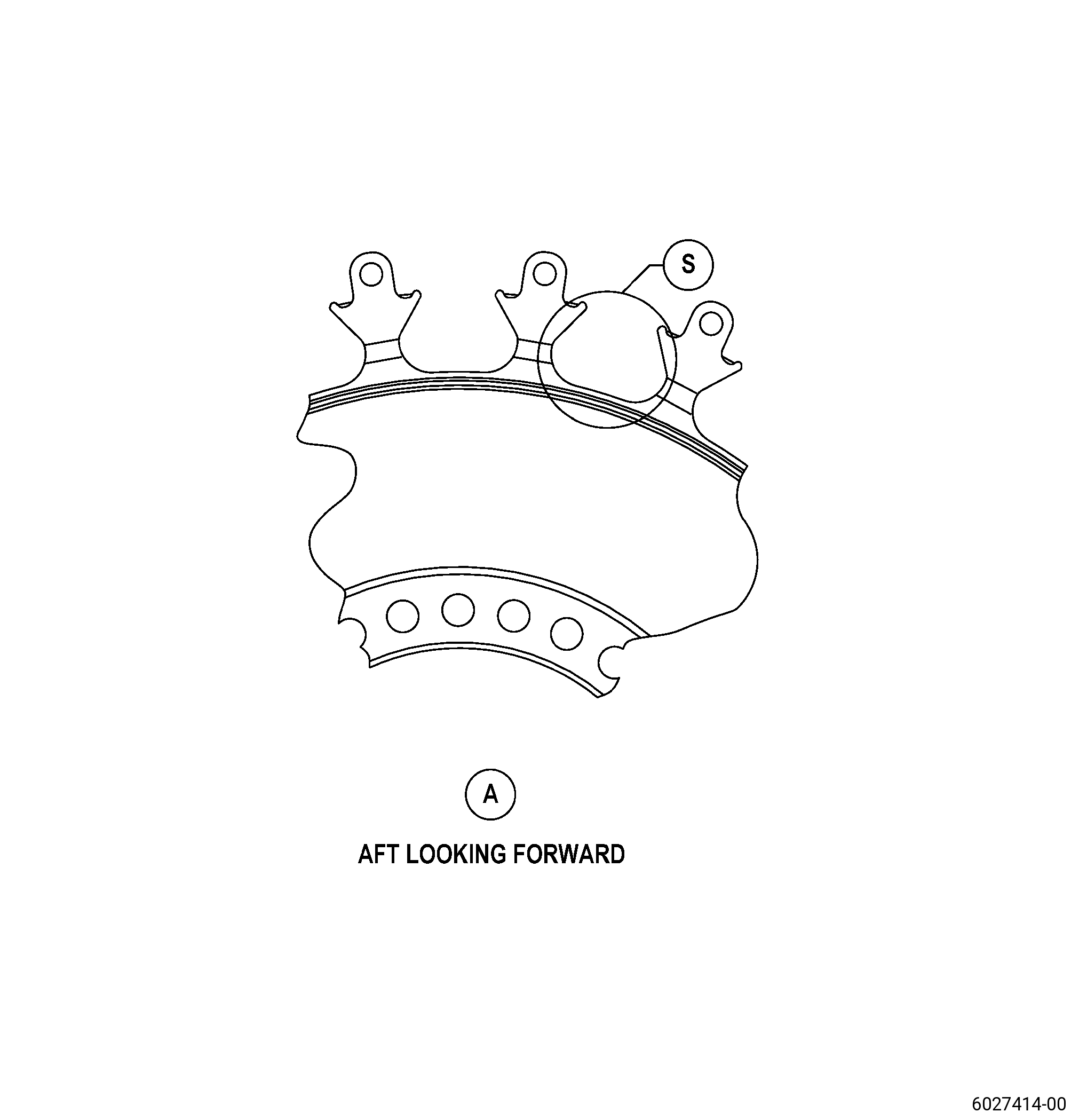
| (p) | Do an inspection of the dovetail slots of the fan disk as follows. Refer to Figure 804. |
| 4 | Wear/fretting on the bottom of the dovetail slots aft disk because of contact with the dovetail key (20-180, 72-00-00) (SIN 8300B): |
| Maximum repairable limit: |
|
| C. | The subsequent table gives a list of the part numbers that are applicable to this procedure. All part numbers are applicable to all paragraphs unless specified differently. |
|
||||||||||||||||||||||
| D. | Proprietary/Complex Process Statement. |
| (1) | None. |
| 2 . | Tools, Equipment, and Materials. |
| NOTE: |
|
| A. | Tools and Equipment. |
| (1) | Special Tools. None. |
| (2) | Standard Tools and Equipment. None. |
| (3) | Locally Manufactured Tools. None. |
| B. | Consumable Materials. |
|
| C. | Referenced Procedures. |
| D. | Expendable Parts. None. |
| E. | SPD Information. |
| (1) | Spares Supplied. None. |
| (2) | Protected Spares. None. |
| (3) | Locally Manufactured Spares. None. |
| F. | Special Solutions. None. |
| G. | Test Specimens. None. |
| 3 . | Dimensional Information. |
| Subtask 72-00-22-220-063 |
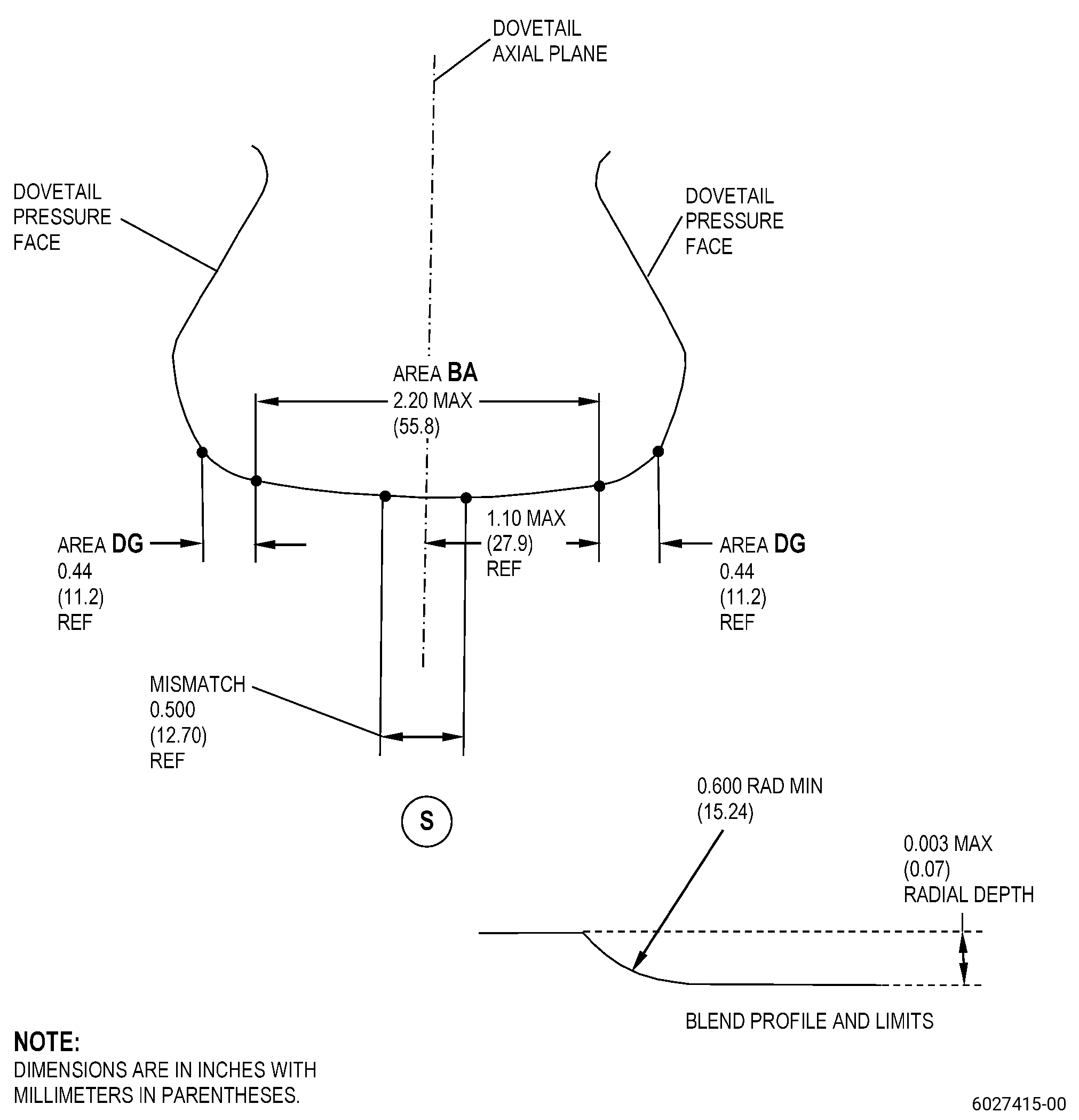
| A. | Refer to Figure 901 and Figure 902 for specified dimensions and locations. |
| NOTE: |
|
| NOTE: |
|
| 4 . | Setup Information. |
| None. |
| 5 . | Procedure. |
| Subtask 72-00-22-160-002 |
| A. | If necessary, clean the damaged area BA on the dovetail slots bottom of the fan disk. Refer to TASK 72-00-22-100-801 (72-00-22, CLEANING 001) and Figure 902. |
| Subtask 72-00-22-350-001 |
| WARNING: |
|
| CAUTION: |
|
| CAUTION: |
|
| CAUTION: |
|
| B. | Blend the damaged area BA on the dovetail slots bottom of the fan disk. Refer to TASK 70-42-00-350-002 (BLENDING AND REMOVAL OF HIGH METAL PROCEDURES), Figure 902, and as follows: |
| (1) | Apply masking with C10-021 plastic tape to the surfaces adjacent to the damaged areas, where blending is not necessary. |
| (2) | Apply masking or give protection, as necessary, to the areas of the module to prevent contamination in the fan booster assembly with particles from high metal removal. |
| (3) | Manually blend 1.25 times the damage depth to fully remove the damage in area BA. Refer to TASK 70-42-00-350-002 (BLENDING AND REMOVAL OF HIGH METAL PROCEDURES), Figure 901 and as follows: |
| (a) | Blending into area DG is not permitted. |
| (b) | Blend in a circumferential direction, not along the axis of the part. |
| (c) | Remove the minimum quantity of parent material necessary to remove the damage and to make the blend agree with the repairable limits. |
| (d) | Make sure that you blend a maximum radial depth of 0.003 inch (0.07 mm), with a minimum blend radius of 0.600 inch (15.24 mm) and to a maximum circumferential blend length of 2.20 inches (55.8 mm). |
| (e) | Make sure that there is a smooth contour transition without a step or cusps. |
| Subtask 72-00-22-220-064 |
| (4) | Do a visual and dimensional inspection of the repaired dovetail slots as follows: |
| (a) | The blend dimensions must agree with the limits specified in Subtask 72-00-22-350-001 (paragraph 5.B.(3)(d)). |
| (b) | Make sure that the blends are contained in area BA. |
| (c) | Make sure that there are no damages on the adjacent radii and pressure faces. |
| Subtask 72-00-22-160-003 |
| C. | Clean the blended area BA on the dovetail slots bottom of the fan disk. Refer to TASK 70-21-00-110-051 (CHEMICAL CLEANING) and TASK 70-21-03-160-001 (CLEANING METHOD NO. 3 - STEAM CLEANING). |
| Subtask 72-00-22-110-003 |
| D. | Etch the blended area BA on the dovetail slots bottom of the fan disk. Refer to TASK 70-24-00-110-033 (ETCHING PROCEDURES FOR FLUORESCENT-PENETRANT INSPECTION), TASK 70-24-01-110-034 (SWAB ETCHING PROCEDURE), and as follows: |
| (1) | Use Class B etchant. |
| Subtask 72-00-22-230-001 |
| E. | Do an inspection of the blended area BA on the dovetail slots bottom of the fan disk. Refer to TASK 70-32-00-200-002 (INDIRECT INSPECTION METHODS), TASK 70-32-03-230-002 (SPOT-FLUORESCENT-PENETRANT INSPECTION), and as follows: |
| (1) | Use Class G penetrant. |
| (2) | Linear indications are not permitted. |
| NOTE: |
|
| (3) | Indications more than 0.015 inch (0.38 mm) are not permitted. |
| Subtask 72-00-22-160-004 |
| WARNING: |
|
| F. | If necessary, clean the blended area BA on the dovetail slots bottom of the fan disk to remove remaining etchant/penetrant. Refer to TASK 70-21-00-110-051 (CHEMICAL CLEANING) and TASK 70-21-03-160-001 (CLEANING METHOD NO. 3 - STEAM CLEANING). |
| Subtask 72-00-22-380-001 |
| G. | Peen the blended area BA on the dovetail slots bottom of the fan disk. Refer to TASK 70-47-04-380-019 (ROTARY FLAP PEENING) and as follows: |
| (1) | Apply masking with C10-021 plastic tape to the surfaces adjacent to the repaired area BA where peening is not necessary. |
| (2) | Apply masking or give protection, as necessary, to the areas of the module to prevent contamination in the fan booster assembly with an accidentally liberated flapper or flapper media lodged in the part or module. |
| (3) | Peen area BA to an intensity of 0.006-0.012N. |
| (4) | There must be a smooth transition on the boundaries from the peening area to the adjacent non-peened areas. |
| (5) | Peening on the adjacent area is permitted if peening is permitted on the area. |
| (6) | Coverage must be a minimum of 100 percent. |
| (7) | Do an intensity verification as follows: |
| (a) | Use a magnetic Almen strip holder. |
| NOTE: |
|
| Subtask 72-00-22-220-065 |
| (8) | Do a visual inspection of the peened surface and make sure that there are no burrs, high metal, metal removal, or unwanted deformation. |
| (9) | Remove the plastic tape. |
| Subtask 72-00-22-160-005 |
| H. | Clean the repaired areas of the dovetail slots bottom of the fan disk. Refer to TASK 70-21-00-110-051 (CHEMICAL CLEANING) and TASK 70-21-03-160-001 (CLEANING METHOD NO. 3 - STEAM CLEANING). |
| Subtask 72-00-22-220-066 |
| I. | Do a final inspection of the fan disk. Refer to TASK 72-00-22-200-801 (72-00-22, INSPECTION 001). |