| GENX-1B CLEANING,INSPECTION,AND REPAIR MANUAL | Dated: 12/27/2023 | |
| CIR 72-30-01 , REPAIR 001 | ||
| HIGH PRESSURE COMPRESSOR STATOR EXTENSION CASE - REPAIR - THREADED INSERT REPLACEMENT | ||
| GENX-1B CLEANING,INSPECTION,AND REPAIR MANUAL | Dated: 12/27/2023 | |
| CIR 72-30-01 , REPAIR 001 | ||
| HIGH PRESSURE COMPRESSOR STATOR EXTENSION CASE - REPAIR - THREADED INSERT REPLACEMENT | ||
| * * * FOR ALL |
| TASK 72-30-01-300-801 |
| 1 . | Threaded Insert Replacement. |
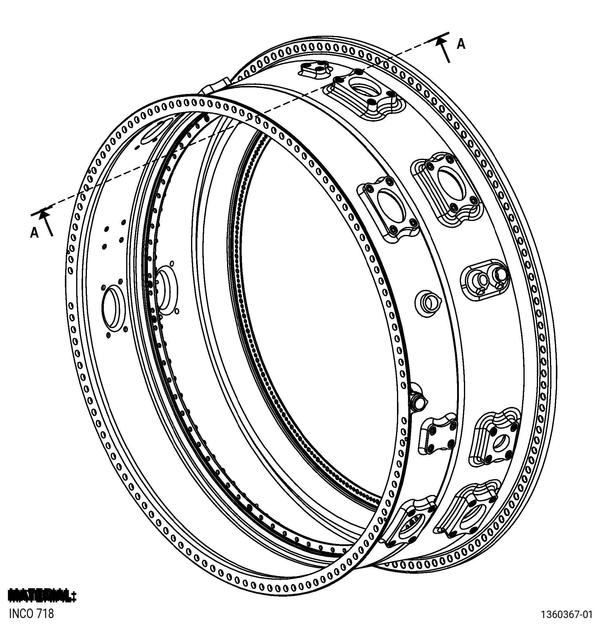
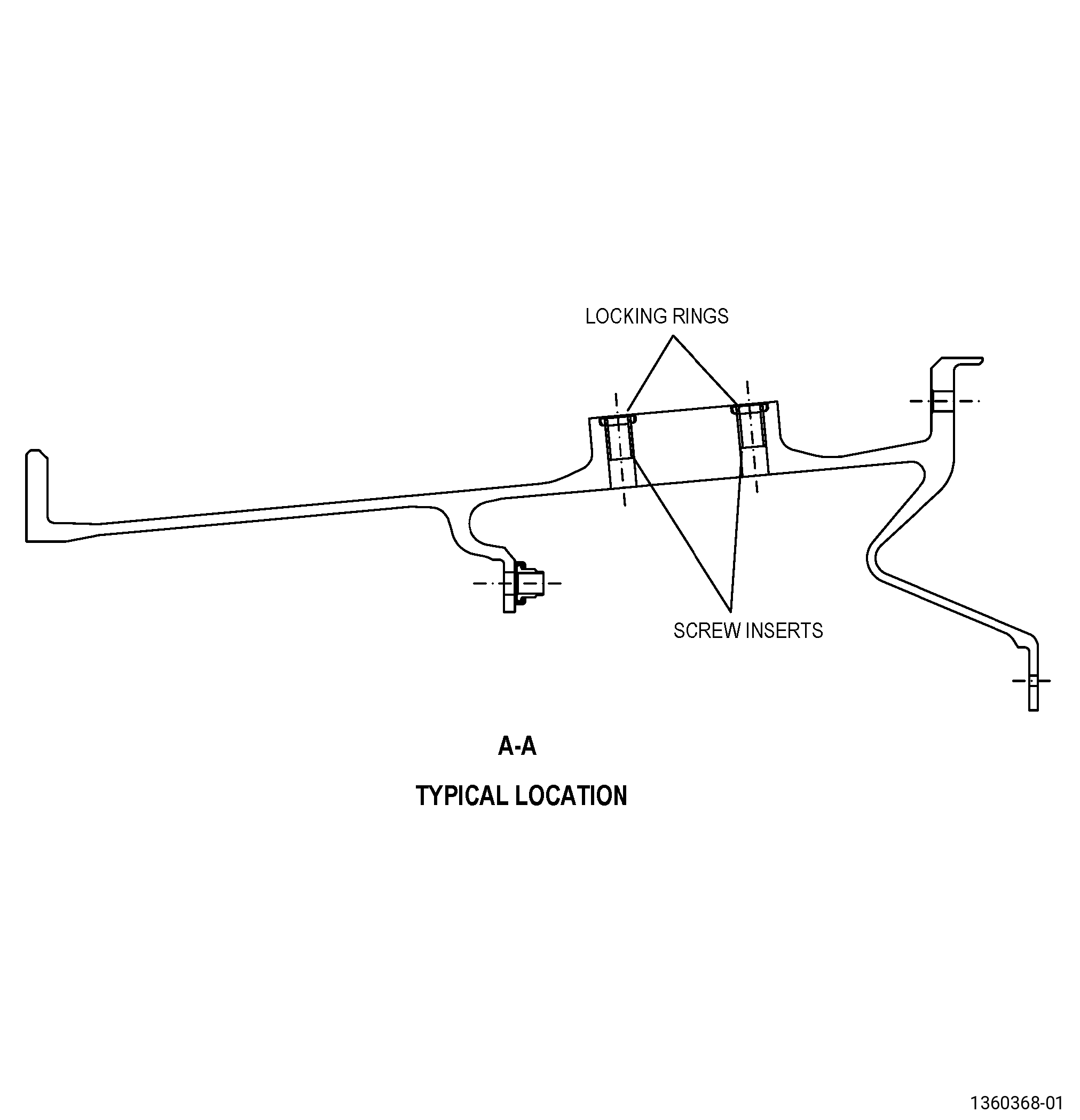
| A. | This procedure gives instructions to repair the high pressure compressor (HPC) stator extension case (extension case) by replacing the damaged threaded inserts. Refer to Figure 901. |
| B. | The following maximum repairable limits apply to this repair: |
| NOTE: |
|
| (4) | Visual Inspection. |
| (b) | Do an inspection of the HPC stator extension case (extension case) (080AL) as follows. Refer to Figure 801. |
| 2 | Damaged threads on the mounting pads: |
| Maximum repairable limit: |
|
| NOTE: |
|
| (e) | Do an inspection of the insert for: |
| 1 | Loss of self-locking quality (0.250-28UNJF): |
| Maximum repairable limit: |
|
| 2 | Looseness or missing: |
| Maximum repairable limit: |
|
| NOTE: |
|
| (ag) | Do an inspection of the HPC stator extension case (extension case) (080AL) as follows. Refer to Figure 811. |
| 2 | Damaged threads on the mounting pads: |
| Maximum repairable limit: |
|
| NOTE: |
|
| C. | The subsequent table gives a list of the part numbers that are applicable to this repair. All part numbers are applicable to all paragraphs unless specified differently. |
|
|||||||||||||||||||||||
| D. | Proprietary/Complex Process Statement. |
| (1) | None. |
| 2 . | Tools, Equipment, and Materials. |
| NOTE: |
|
| A. | Tools and Equipment. |
| (1) | Special Tools. None. |
| (2) | Standard Tools and Equipment. |
| (3) | Locally Manufactured Tools. None. |
| B. | Consumable Materials. None. |
| C. | Referenced Procedures. |
|
| D. | Expendable Parts. None. |
| E. | SPD Information. |
|
| F. | Special Solutions. None. |
| G. | Test Specimens. None. |
| 3 . | Dimensional Information. |
| Subtask 72-30-01-220-057 |
| A. | Refer to Figure 901 for specified dimensions and locations. |
| NOTE: |
|
| NOTE: |
|
| 4 . | Setup Information. |
| None. |
| 5 . | Procedure. |
| Subtask 72-30-01-100-001 |
| A. | If necessary, clean the HPC extension case. Refer to TASK 72-30-01-100-801 (72-30-01, CLEANING 001). |
| Subtask 72-30-01-350-001 |
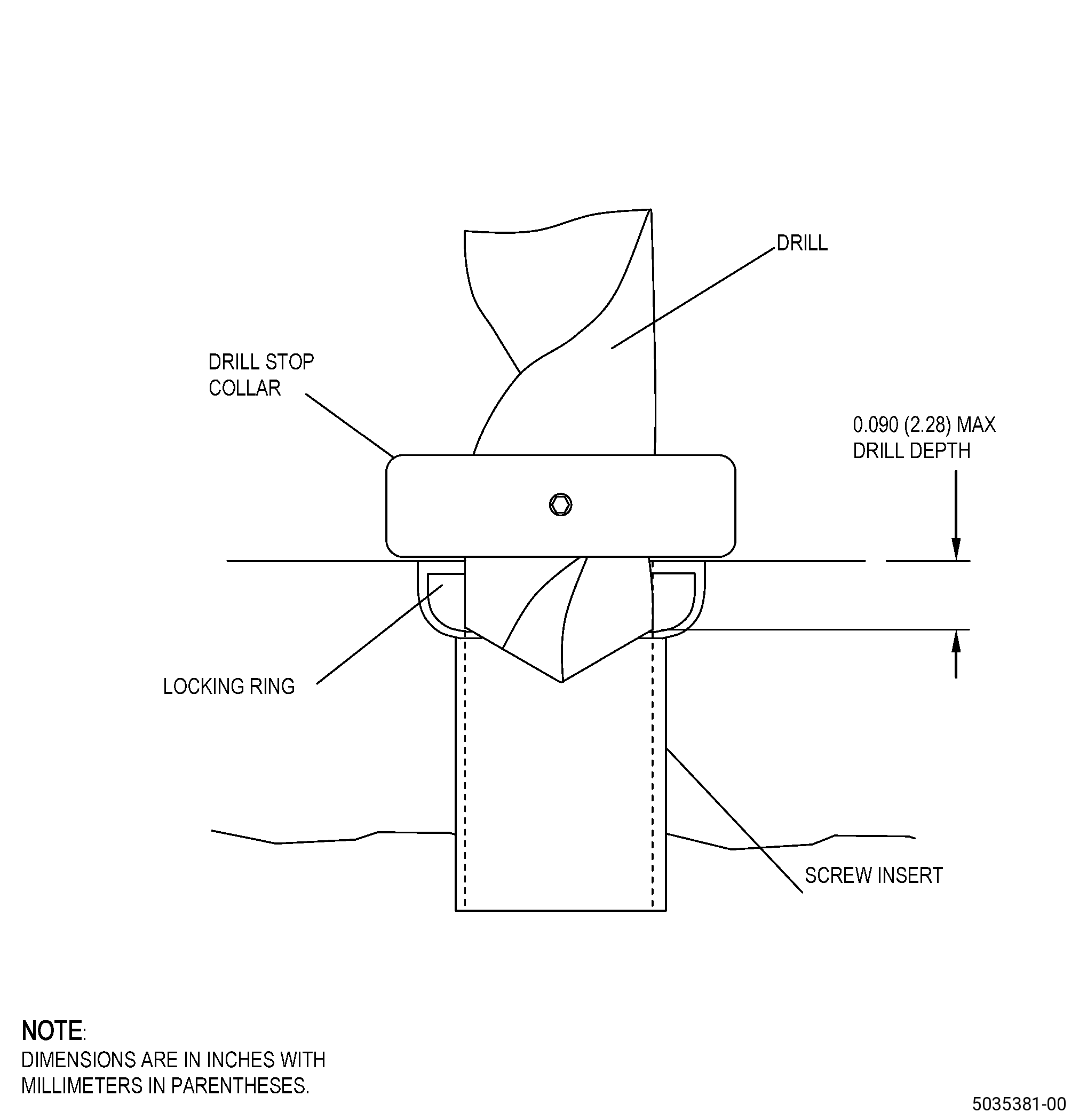
| B. | Remove the damaged insert from the HPC extension case. Refer to TASK 70-48-22-350-801 (REPLACEMENT OF RING-LOCK INSERT), Figure 902, and do as follows: |
| NOTE: |
|
| (1) | Set-up the drill as follows: |
| (a) | Use a 0.2785 inch (7.074 mm) diameter drill. |
| (b) | Install a drill stop collar on the drill bit to a drill depth of 0.080-0.090 inch (2.03-2.28 mm). |
| (2) | Align the drill with the center line of the damaged insert. |
| Subtask 72-30-01-320-001 |
| WARNING: |
|
| CAUTION: |
|
| CAUTION: |
|
| (3) | Drill into the threaded insert to a depth of 0.080-0.090 inch (2.03-2.28 mm). |
| Subtask 72-30-01-350-003 |
| WARNING: |
|
| (4) | Use a pointed punch to remove the locking ring and as follows: |
| (a) | Discard the locking ring that you removed. |
| (5) | Use an allen key to remove the damaged threaded insert. |
| NOTE: |
|
| (6) | Remove all unwanted material from the extension case repair area. |
| Subtask 72-30-01-220-078 |
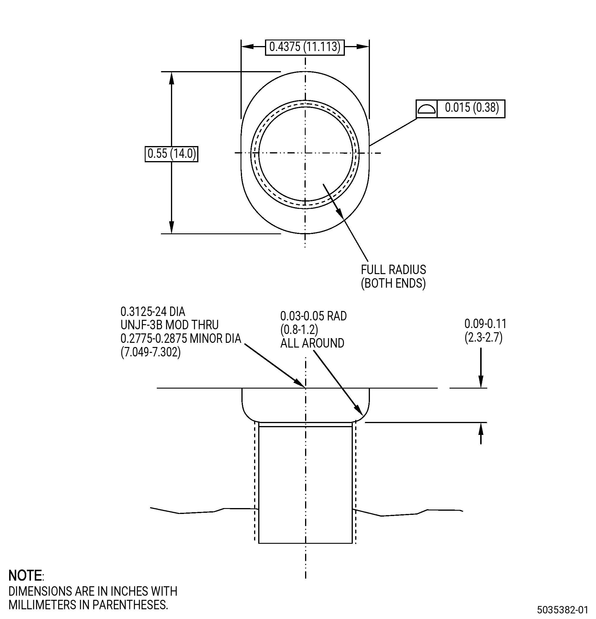
| (7) | Do a visual inspection of the threads and counterbore of the extension case repair area. Refer to Figure 903 and as follows: |
| (a) | If necessary, remove the high metal from the threaded hole with a tap to chase the threads. |
| (b) | Use clean compressed air to remove the loose metal chips from the tapped hole. |
| (c) | If more than the first thread remains damaged, this part cannot be repaired by this procedure. |
| Subtask 72-30-01-220-082 |
| (8) | Do an inspection of the threads of the extension case repair area and as follows: |
| (a) | Conduct No-Go pin gauge check of the threaded holes: |
| Maximum serviceable limit: |
|
| Maximum repairable limit: |
|
| Repair method: |
|
| Subtask 72-30-01-350-004 |
| C. | Install the new insert, 1693M83P04 , and the new locking ring, 1689M74P02 , in the HPC extension case. Refer to AS3507, Installation and Removal of Thin Wall, Self-Locking, Short and Long Length Inserts, Figure 903, and as follows: |
| (1) | Use the same size insert as the damaged insert that you removed. |
| (2) | Install the new threaded insert into the threaded hole of the extension case as follows: |
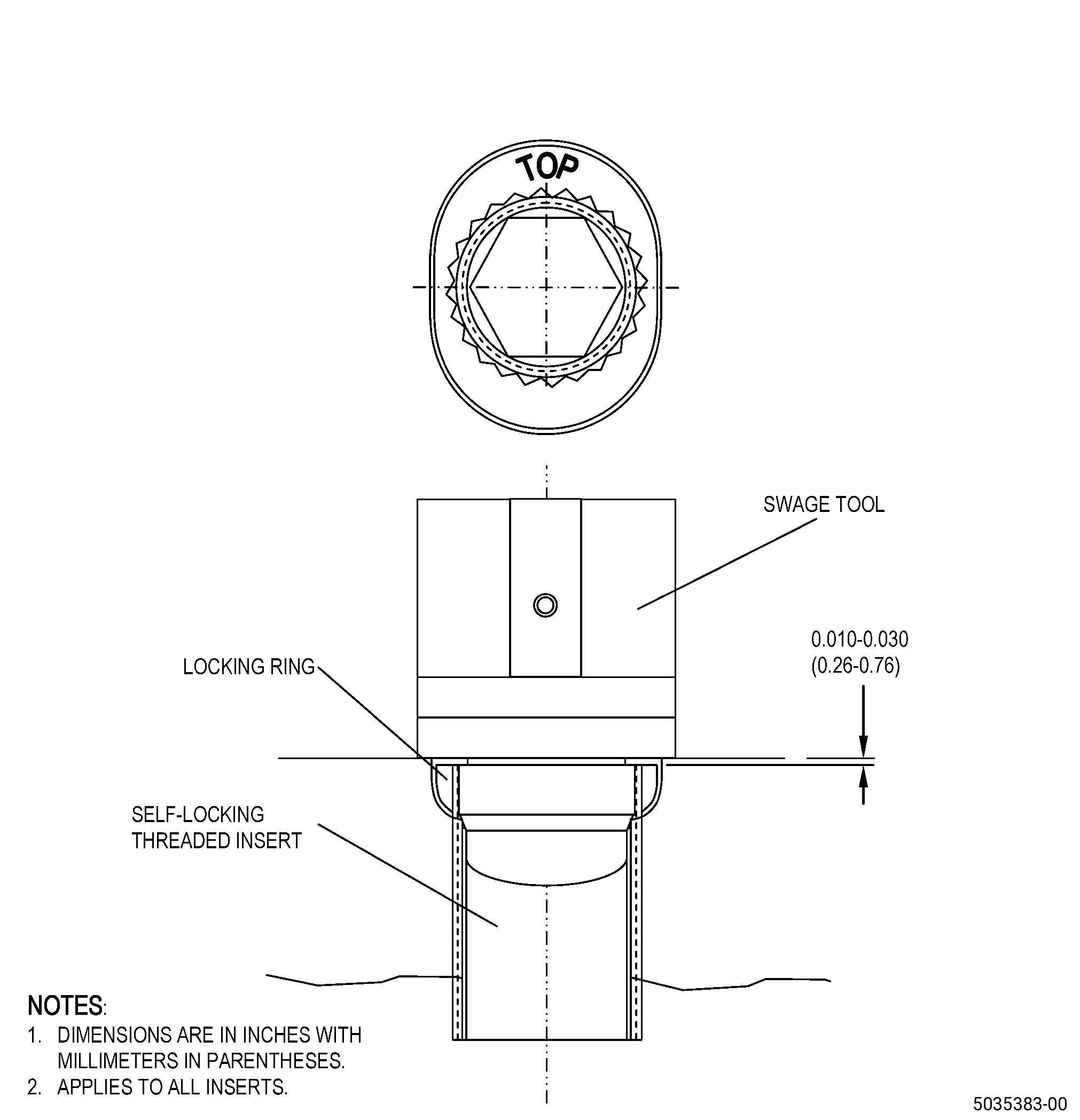
| (a) | Turn the new insert until the top face of the insert is 0.010-0.030 inch (0.26-0.76 mm) below the location face surface of the case. |
| Subtask 72-30-01-350-005 |
| (3) | Install the new locking ring on the insert and into the oval shaped hole as follows: |
| (a) | Use locking ring, 1689M74P02 . |
| (b) | The word top on the lock ring must face outward from the case. |
| (4) | Swage the new insert into the locking ring. |
| Subtask 72-30-01-220-058 |
| D. | Do an inspection of the new insert and new locking ring installation, and as follows: |
| (1) | Use 10X magnification. |
| (2) | Make sure that the insert serrations are swaged into the serrations of the locking ring. |
| (3) | Make sure that the locking ring and insert are below the surface of the extension case. |
| Subtask 72-30-01-350-006 |
| E. | Remove all unwanted material from the extension case repair area. |