| GENX-1B CLEANING,INSPECTION,AND REPAIR MANUAL | Dated: 09/02/2021 | |
| CIR 72-00-30 , INSPECTION 001 | ||
| HIGH PRESSURE COMPRESSOR ASSEMBLY - INSPECTION | ||
| GENX-1B CLEANING,INSPECTION,AND REPAIR MANUAL | Dated: 09/02/2021 | |
| CIR 72-00-30 , INSPECTION 001 | ||
| HIGH PRESSURE COMPRESSOR ASSEMBLY - INSPECTION | ||
| * * * FOR ALL |
| TASK 72-00-30-200-801 |
| 1 . | General. |
| A. | This procedure gives instructions to do an inspection of the high pressure compressor (HPC) assembly: |
| • |
|
| • |
|
| • |
|
| • |
|
| B. | Any sub-assembly or part removed for access or limited workscope must be inspected in accordance with criteria in this section. If there is no criteria, the sub-assembly or part must receive a general visual inspection (GVI) for continued serviceability. Refer to TASK 72-00-00-200-805 (72-00-00, INSPECTION 001) . If required, the component can be hand-cleaned to do a visual inspection. Refer to TASK 70-21-01-110-001 (CLEANING METHOD 1 - SOLVENT DEGREASING) or TASK 70-21-03-160-001 (CLEANING METHOD 3 - STEAM CLEANING) . GVI can not be done to components identified in TASK 05-21-00-200-801 (05-21-00, LIFE LIMITS 001) that become piece part. These components must have their appropriate mandatory inspections done, unless stated differently in an applicable Service Bulletin. |
| (1) | If you replace the stage 9 vane sector or honeycomb seal, refer to TASK 72-30-00-800-802 (72-30-00, SPECIAL PROCEDURE 002). |
| NOTE: |
|
| (2) | If you replace the stage 9 vane sector or honeycomb seal and TASK 72-30-00-800-802 (72-30-00, SPECIAL PROCEDURE 002) is not done, then the overhaul of the HPC stage 6-10 spool must take place. |
| NOTE: |
|
| (a) | For the replacement of the seal tooth coating, refer to TASK 72-31-45-300-802 (72-31-45, REPAIR 002). |
| C. | If you do this procedure and find that an assembly or part is unserviceable, refer to the applicable section of the engine manual for more disassembly and inspection procedures for the assembly or part. |
| D. | If you or other personnel will fully disassemble the HPC assembly, this inspection is not necessary. Refer to the applicable section of the engine manual for the inspection procedure for each part. |
| E. | The maintenance instructions in this Manual do not purport to cover all details or variations in equipment, nor do they provide for every possible contingency to be met in connection with installation, operation, maintenance, or GEAE certified repair facilities. The maintenance instructions are intended to be all-inclusive for a complete teardown and overhaul of the component or sub assembly. The individual procedures as written are one sequence based on General Electric experience. Alternate sequences to these maintenance instructions are at the discretion of the operator and/or overhaul shop provided the intent of the maintenance instructions is met. The operator and/or overhaul shop can select specific tasks to partially disassemble and assemble hardware or subassemblies based upon the on demand maintenance requirement of the individual engine work scope provided the final assembly configuration and requirements contained in the manual have been met. |
| F. | There are two configurations of the variable stator vane (VSV) actuating rings: |
| • |
|
| • |
|
| 2 . | Tools, Equipment, and Materials. |
| NOTE: |
|
| A. | Tools and Equipment. |
| (1) | Special Tools. None. |
| (2) | Standard Tools and Equipment. None. |
| (3) | Locally Manufactured Tools. None. |
| B. | Consumable Materials. None. |
| C. | Referenced Procedures. |
| D. | Expendable Parts. None. |
| 3 . | Specific Inspection Procedure. |
| Subtask 72-00-30-250-001 |
| A. | Do an eddy current inspection of the coated seal teeth on the CDP rotating seal (CDP seal) (01-460 , 72-31-00) (SIN 050NC) or (02-460 , 72-31-00) (SIN 050NC). Refer to TASK 72-00-31-800-801 (72-00-31, SPECIAL PROCEDURES 001). |
| NOTE: |
|
| Subtask 72-00-30-230-001 |
| B. | Do a fluorescent penetrant inspection of any visual indication to confirm cracks. Refer to TASK 70-32-02-230-001 (FLUORESCENT PENETRANT INSPECTION). |
| 4 . | Visual Inspection. |
| CAUTION: |
|
| Subtask 72-00-30-220-001 |
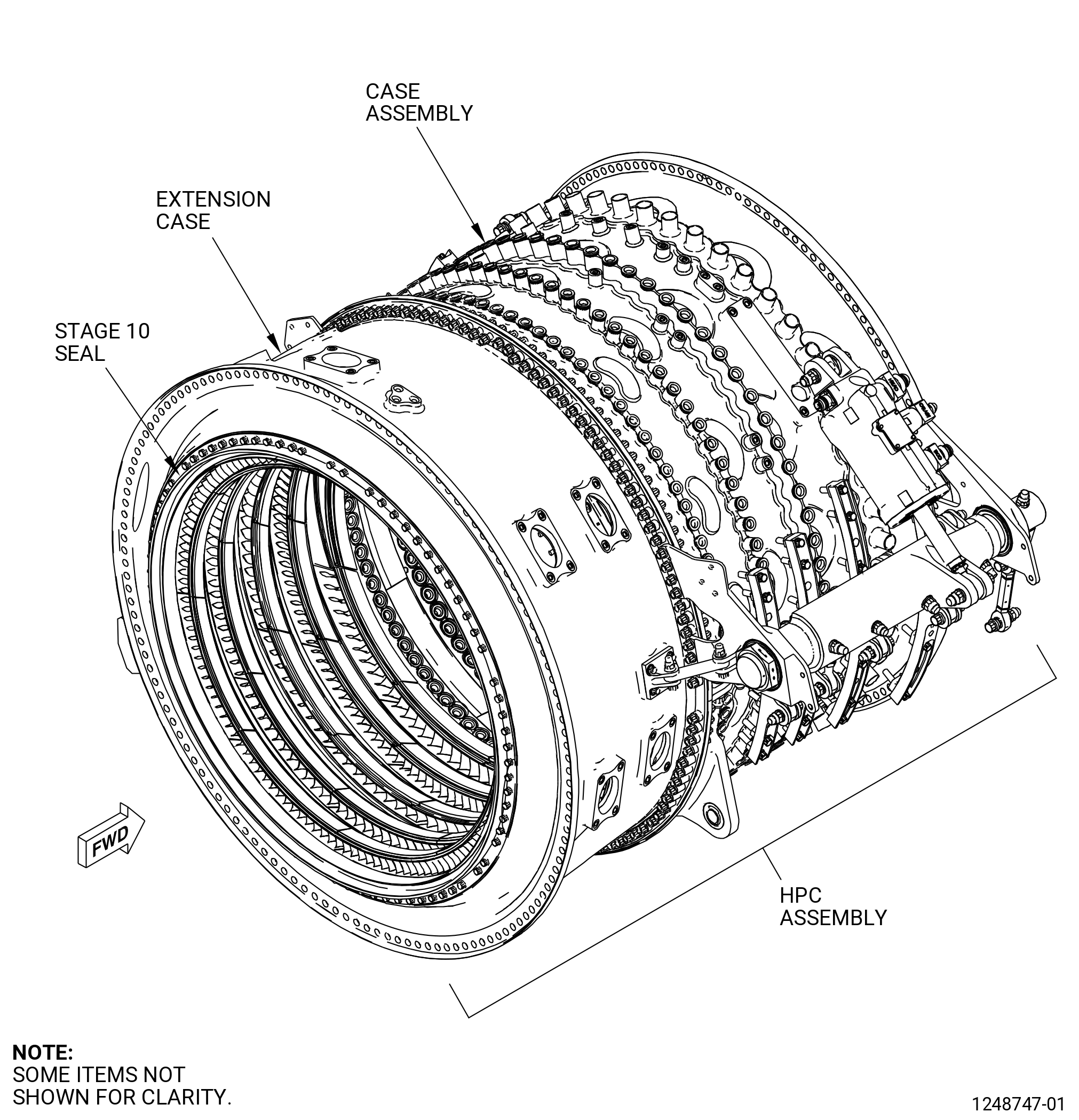
| A. | Do an inspection of the HPC stator forward case assembly (case assembly) (073A0) as follows. Refer to Figure 801. |
| (1) | Cracks in the outer surface (skin): |
| Maximum serviceable limit: |
|
| Repair method: |
|
| Subtask 72-00-30-220-002 |
| (2) | Cracks in the ribs: |
| Maximum serviceable limit: |
|
| Maximum repairable limit: |
|
| Repair method: |
|
| Subtask 72-00-30-220-003 |
| (3) | Cracks in the horizontal and circumferential flanges: |
| Maximum serviceable limit: |
|
| Repair method: |
|
| Subtask 72-00-30-220-004 |
| (4) | Nuts and bolts that are loose, broken, or missing: |
| Maximum serviceable limit: |
|
| Maximum serviceable limit: |
|
| Repair method: |
|
| Subtask 72-00-30-220-005 |
| (5) | Discoloration (hot spots) on all surfaces: |
| Maximum serviceable limit: |
|
| Repair method: |
|
| Subtask 72-00-30-220-006 |
| B. | Do an inspection of the HPC stator extension case (extension case) (080AL) as follows. Refer to Figure 801. |
| (1) | Nicks, pits, scores, and scratches on all surfaces: |
| Maximum serviceable limit: |
|
| Maximum repairable limit: |
|
| Repair method: |
|
| Subtask 72-00-30-220-047 |
| (2) | Damaged threads on the mounting pads: |
| Maximum serviceable limit: |
|
| Repair method: |
|
| Subtask 72-00-30-220-011 |
| CAUTION: |
|
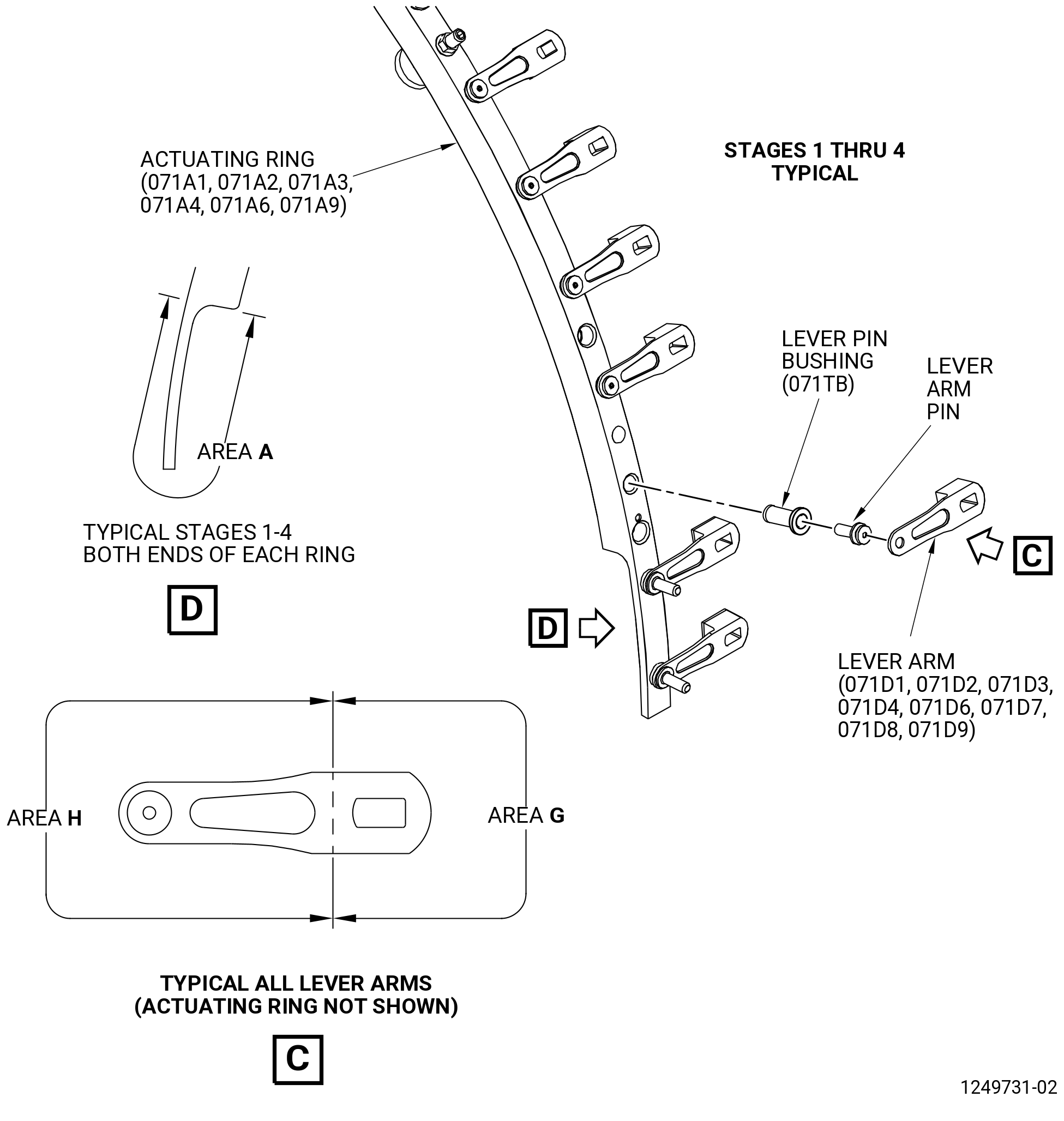
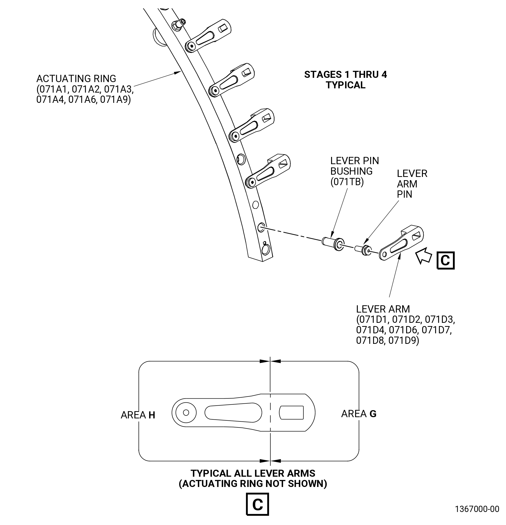
| C. | Do an inspection of all areas of each of the VSV stages 1-4 lever arms (lever arms) (071D1, 071D2, 071D3, 071D4, 071D6, 071D7, 071D8, 071D9) as follows. Refer to Figure 802. |
| (1) | Cracks: |
| Maximum serviceable limit: |
|
| Repair method: |
|
|
|
| Subtask 72-00-30-220-012 |
| (2) | Distortion: |
| Maximum serviceable limit: |
|
| Repair method: |
|
| Subtask 72-00-30-220-013 |
| (3) | Nicks, dents, and scratches in area H: |
| Maximum serviceable limit: |
|
| Repair method: |
|
| Subtask 72-00-30-220-014 |
| (4) | Nicks, dents, and scratches in area G: |
| Maximum serviceable limit: |
|
| Maximum repairable limit: |
|
| Repair method: |
|
| Subtask 72-00-30-220-015 |
| D. | Do an inspection of the pin of each lever arm as follows. Refer to Figure 802. |
| (1) | Distortion: |
| Maximum serviceable limit: |
|
| Repair method: |
|
| Subtask 72-00-30-220-016 |
| (2) | Looseness of the heads: |
| Maximum serviceable limit: |
|
| Repair method: |
|
| Subtask 72-00-30-220-017 |
| (3) | Breaks: |
| Maximum serviceable limit: |
|
| Repair method: |
|
| Subtask 72-00-30-220-018 |
| CAUTION: |
|
| E. | Do an inspection of all areas of each of the upper and lower HPC stator stages 1-4 VSV actuating rings (actuating rings) (071A1, 071A2, 071A3, 071A4, 071A6, 071A9) as follows. Refer to Figure 802. |
| (1) | Cracks: |
| Maximum serviceable limit: |
|
| Repair method: |
|
| Subtask 72-00-30-220-019 |
| (2) | Distortion (twists or bends): |
| Maximum serviceable limit: |
|
| Repair method: |
|
| Subtask 72-00-30-220-020 |
| (3) | Scratches: |
| Maximum serviceable limit: |
|
| • |
|
| • |
|
| Maximum repairable limit: |
|
| Repair method: |
|
| Subtask 72-00-30-220-021 |
| (4) | Nicks and dents (does not include area A): |
| Maximum serviceable limit: |
|
| Maximum repairable limit: |
|
| Repair method: |
|
| Subtask 72-00-30-220-040 |
| * * * PRE SB 72-0052( Introduction of New VSV Lever Arm System ) |
| (5) | Nicks or dents in area A: |
| Maximum serviceable limit: |
|
| Repair method: |
|
| NOTE: |
|
| * * * END PRE SB 72-0052 |
| Subtask 72-00-30-220-022 |
| F. | Do an inspection of each of the lever pin bushings (bushings) of the actuating rings as follows. Refer to Figure 802. |
| (1) | Bushings that are broken or worn: |
| Maximum serviceable limit: |
|
| Repair method: |
|
| Subtask 72-00-30-220-023 |
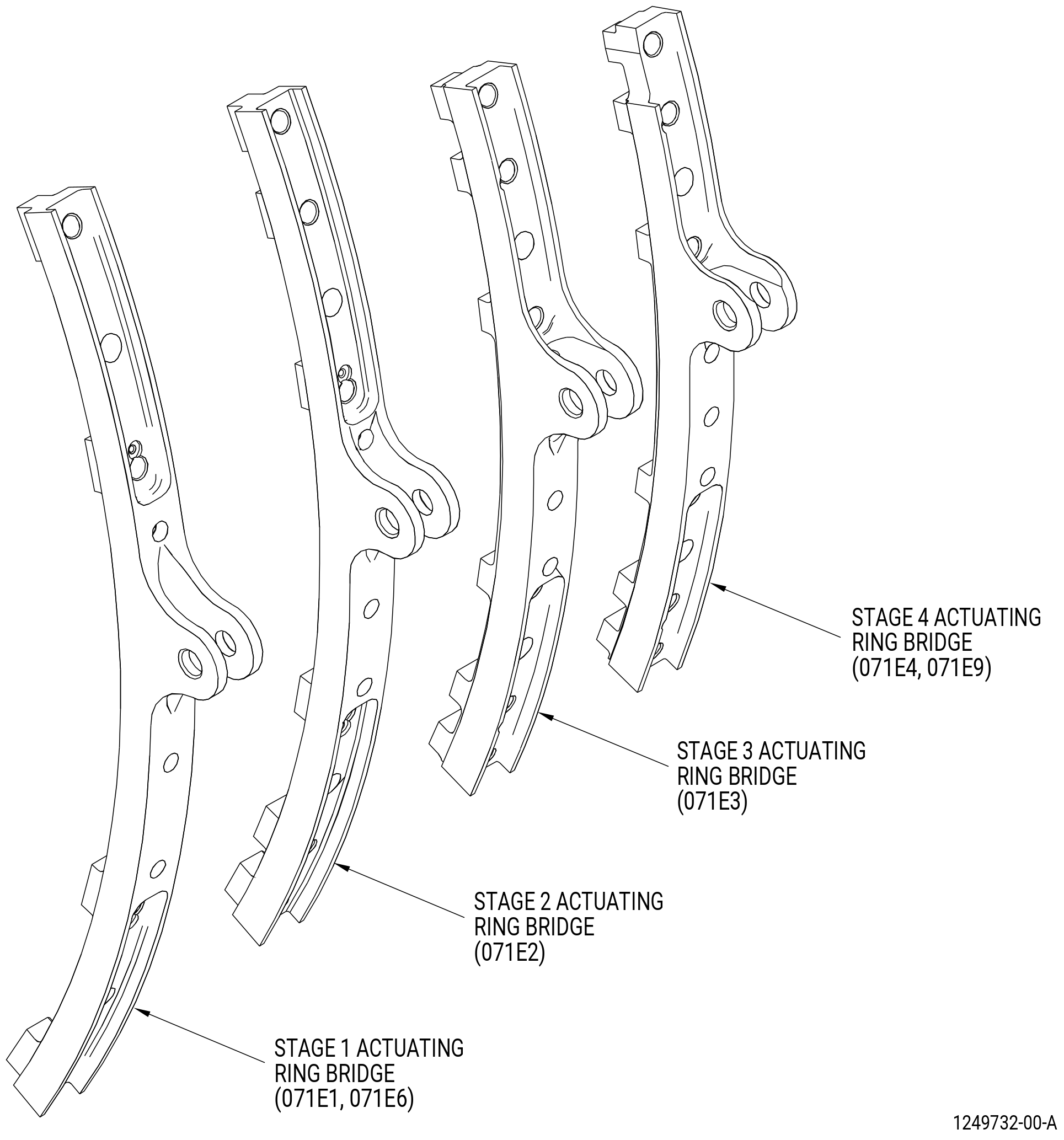
| G. | Do an inspection of each of the VSV stages 1-4 actuating ring bridges (bridges) (071E1, 071E2, 071E3, 071E4, 071E6, 071E9) on the actuating rings as follows. Refer to Figure 802. |
| (1) | Cracks or breaks: |
| Maximum serviceable limit: |
|
| Repair method: |
|
| Subtask 72-00-30-220-036 |
| (2) | Nicks, dents, and scratches: |
| Maximum serviceable limit: |
|
| Maximum repairable limit: |
|
| Repair method: |
|
| Subtask 72-00-30-220-024 |
| CAUTION: |
|
| H. | Do an inspection of each torque shaft (07500-2, 07501-2) as follows. Refer to Figure 802. |
| (1) | Cracks: |
| Maximum serviceable limit: |
|
| Repair method: |
|
| Subtask 72-00-30-220-025 |
| (2) | Nicks, dents, and scratches: |
| Maximum serviceable limit: |
|
| Maximum repairable limit: |
|
| Repair method: |
|
| Subtask 72-00-30-220-026 |
| CAUTION: |
|
| I. | Do an inspection of each of the turnbuckles (07500-24, 07501-24) as follows. Refer to Figure 802. |
| (1) | Cracks: |
| Maximum serviceable limit: |
|
| Repair method: |
|
| Subtask 72-00-30-220-027 |
| (2) | Nicks, dents, scores, scratches, and pits: |
| Maximum serviceable limit: |
|
| Maximum repairable limit: |
|
| Repair method: |
|
| Subtask 72-00-30-220-028 |
| (3) | Looseness of the ball of each spherical bearing: |
| Maximum serviceable limit: |
|
| Repair method: |
|
| Subtask 72-00-30-220-029 |
| CAUTION: |
|
| J. | Do an inspection of the forward supports (07500-3, 07501-3) and aft supports (07500-4, 07501-4) that attach the torque shafts (07500-2, 07501-2) to the case assembly (073A0) as follows. Refer to Figure 802. |
| (1) | Cracks: |
| Maximum serviceable limit: |
|
| Repair method: |
|
| Subtask 72-00-30-220-030 |
| (2) | Nicks, dents, scores, scratches, and pits: |
| Maximum serviceable limit: |
|
| Maximum repairable limit: |
|
| Repair method: |
|
| Subtask 72-00-30-220-031 |
| (3) | Looseness of the ball of each spherical bearing: |
| Maximum serviceable limit: |
|
| Repair method: |
|
| Subtask 72-00-30-220-037 |
| K. | Do an inspection of the AGB mounts for: |
| (1) | Cracks: |
| Maximum serviceable limit: |
|
| Repair method: |
|
| Subtask 72-00-30-220-038 |
| (2) | Nicks, dents, and scratches (does not include spherical bearing): |
| Maximum serviceable limit: |
|
| Repair method: |
|
| Subtask 72-00-30-220-039 |
| (3) | Wear, fretting, and galling on the AGB support mount lugs: |
| Maximum serviceable limit: |
|
| Repair method: |
|
| Subtask 72-00-30-220-041 |
| L. | Do an inspection in the AGB mount spherical bearings of the HPC forward lower case assembly as follows. Refer to Figure 803. |
| (1) | Circumferential movement of the ball: |
| Maximum serviceable limit: |
|
| Repair method: |
|
| Subtask 72-00-30-220-042 |
| (2) | Axial looseness of the outer race in the AGB mount: |
| Maximum serviceable limit: |
|
| Repair method: |
|
| Subtask 72-00-30-220-043 |
| (3) | Nicks, dents, and scratches of the spherical surfaces and the ID of the ball: |
| Maximum serviceable limit: |
|
| Repair method: |
|
| Subtask 72-00-30-220-044 |
| (4) | Galling, fretting or wear on the spherical surfaces, the ID (diameters BA and BB), and the lateral faces of the ball. Refer to Figure 803. |
| Maximum serviceable limit: |
|
| Repair method: |
|
| Subtask 72-00-30-220-045 |
| (5) | Radial movement of the ball: |
| Maximum serviceable limit: |
|
| Repair method: |
|
| Subtask 72-00-30-220-046 |
| (6) | Axial movement of the ball: |
| Maximum serviceable limit: |
|
| Repair method: |
|
| Subtask 72-00-30-220-032 |
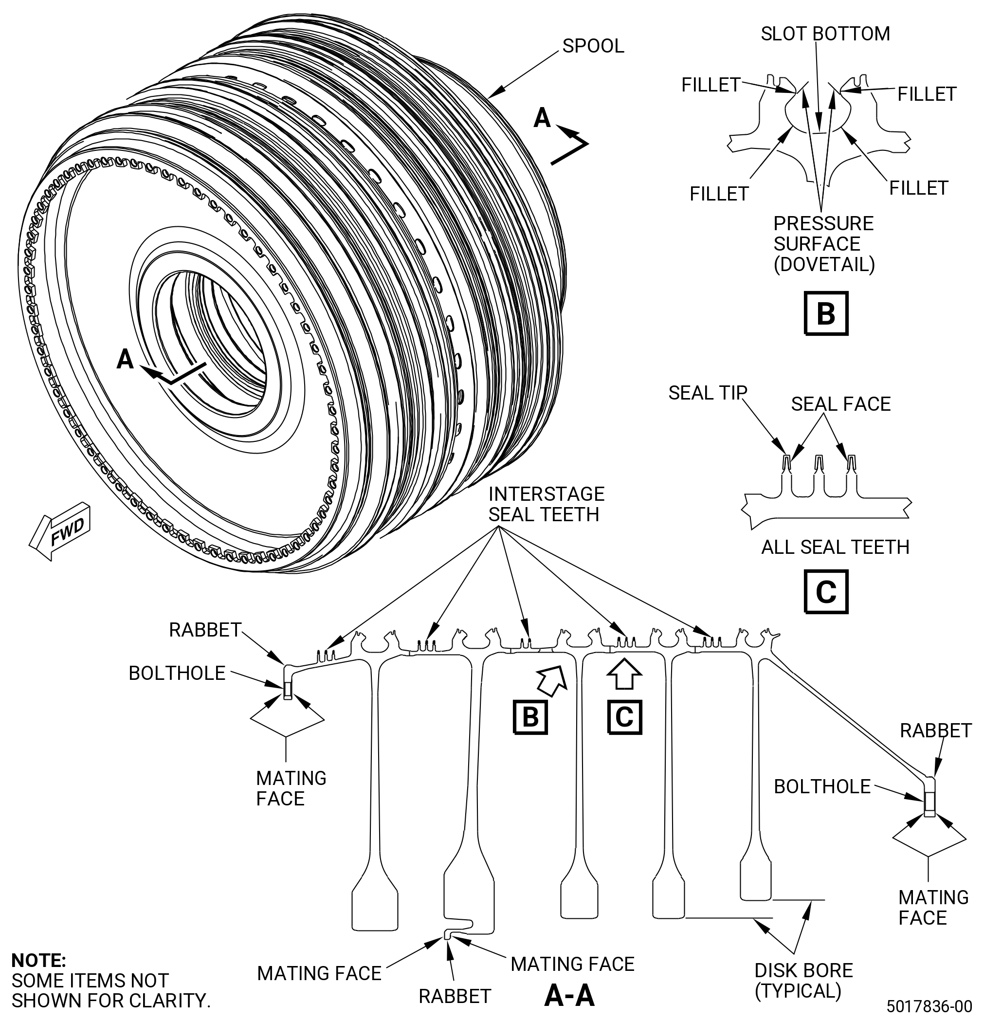
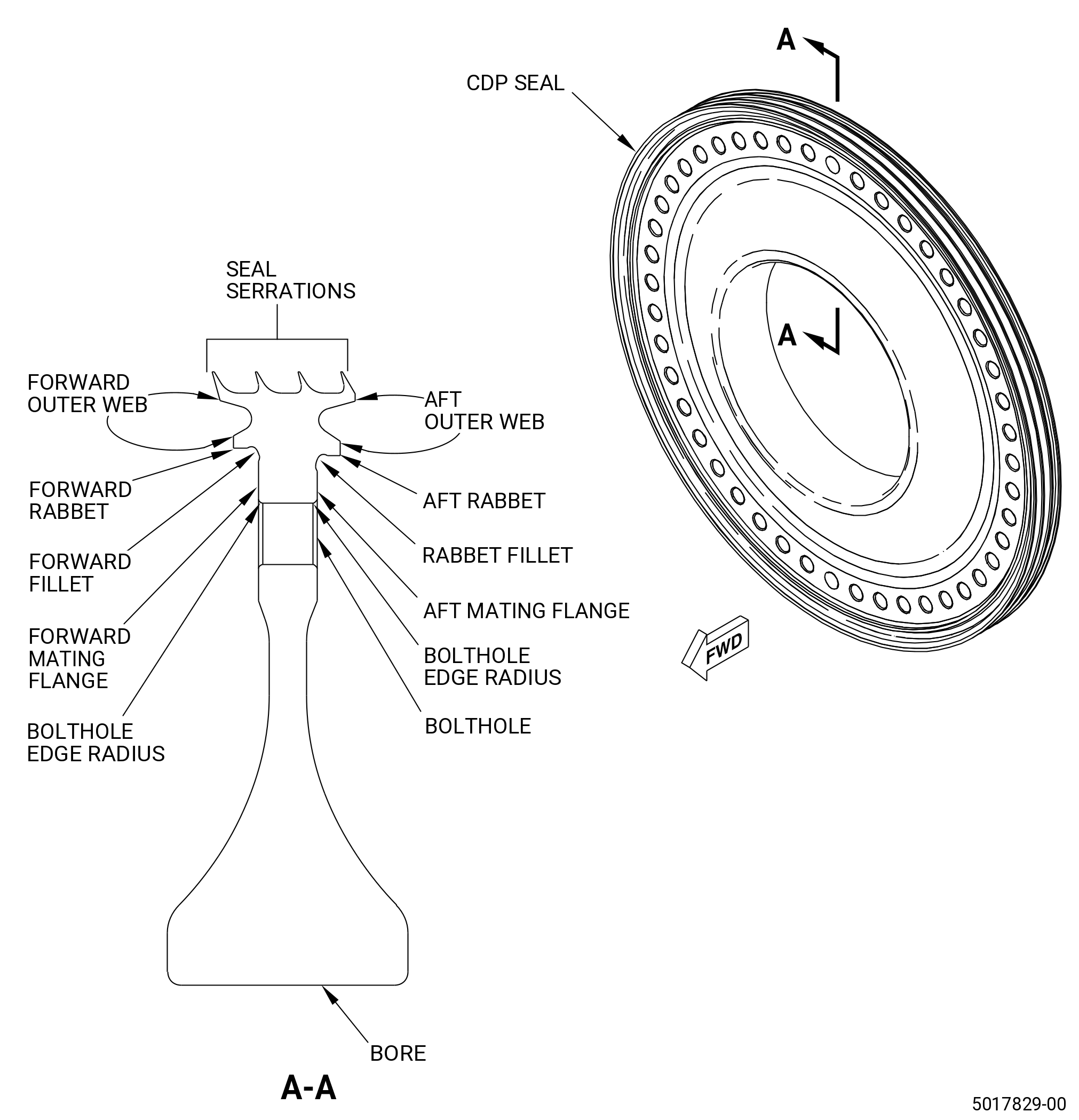
| M. | Do an inspection of the HPC rotor stage 6-10 spool (spool) (050AR) and CDP rotating seal (CDP seal) (050NC) as follows. Refer to Figure 804 and Figure 805. |
| (1) | Cracks: |
| Maximum serviceable limit: |
|
| Repair method: |
|
| Subtask 72-00-30-220-033 |
| (2) | Nicks, dents, and scratches: |
| Maximum serviceable limit: |
|
| Repair method: |
|
| Subtask 72-00-30-220-048 |
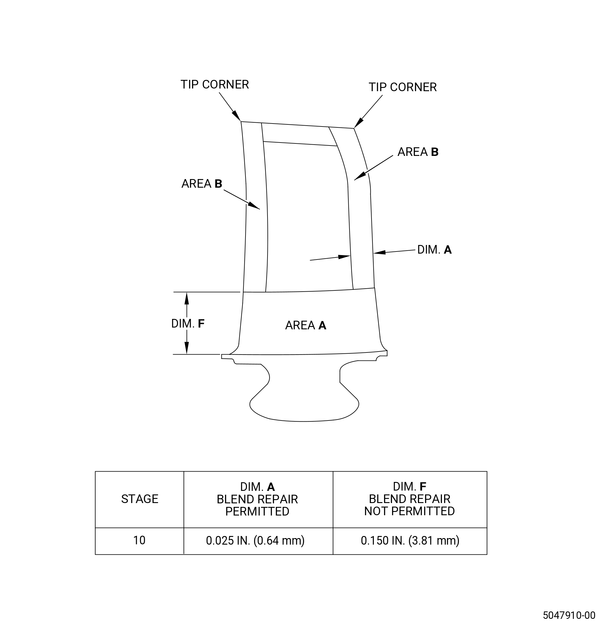
| N. | Do an inspection of stage 10 blades. Refer to Figure 806 and do as follows: |
| (1) | Nicks, dents, and scratches on the leading and trailing edges of the airfoil in area A (does not include root fillet radius): |
| Maximum serviceable limit: |
|
| Repair method: |
|
| Subtask 72-00-30-220-049 |
| (2) | Nicks, pits, dents, and scratches on the leading and trailing edges of the airfoil in area B: |
| Maximum serviceable limit: |
|
| Maximum repairable limit: |
|
| Repair method: |
|
| Subtask 72-00-30-220-050 |
| (3) | Nicks and pits in the fillet area: |
| Maximum serviceable limit: |
|
| Repair method: |
|
| Subtask 72-00-30-220-051 |
| (4) | Dents in fillet except leading edge of fillet: |
| Maximum serviceable limit: |
|
| Repair method: |
|
| Subtask 72-00-30-220-052 |
| (5) | Dents in leading edge of fillet: |
| Maximum serviceable limit: |
|
| Repair method: |
|
| Subtask 72-00-30-220-053 |
| (6) | Scratches in the fillet area (does not include transverse scratches): |
| Maximum serviceable limit: |
|
| Repair method: |
|
| Subtask 72-00-30-220-054 |
| (7) | Tears and cracks on the leading and trailing edges in area A including fillet area: |
| Maximum serviceable limit: |
|
| Repair method: |
|
| Subtask 72-00-30-220-057 |
| (8) | Tears and cracks on the leading and trailing edges in area B: |
| Maximum serviceable limit: |
|
| Maximum repairable limit: |
|
| Repair method: |
|
| Subtask 72-00-30-220-055 |
| (9) | Do an inspection of the blade platform flowpath surface and aft edges for nicks, dents, pits, and scratches: |
| Maximum serviceable limit: |
|
| Repair method: |
|
| Subtask 72-00-30-220-056 |
| (10) | Missing coating on all surfaces: |
| Maximum serviceable limit: |
|